Page 1 of 279

1Engine and peripherals
V2 MR-376-X76-17B050$TOC.mif
V2
17B
"The repair procedures given by the manufacturer in this document are based on the
technical specifications current when it was prepared.
The procedures may be modified as a result of changes introduced by the
manufacturer in the production of the various component units and accessories from
which his vehicles are constructed."
V2
All rights reserved by Renault s.a.s.
Edition Anglaise
Copying or translating, in part or in full, of this document or use of the service part
reference numbering system is forbidden without the prior written authority of
Renault s.a.s.
© Renault s.a.s. 2014
PETROL INJECTION
V42 Injection
Program No.: 2A
Vdiag No.: 04, 05, 06, 14, 16, 18
Fault finding – Introduction 17B - 2
Fault finding – List and location of components 17B - 4
Fault finding – Role of components 17B - 5
Fault finding – Operating diagram 17B - 7
Fault finding – Features 17B - 9
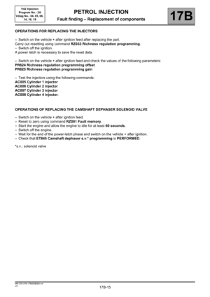
Fault finding – Replacement of components 17B - 12
Fault finding – Fault summary table 17B - 16
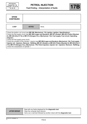
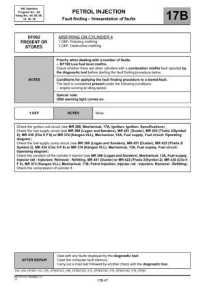
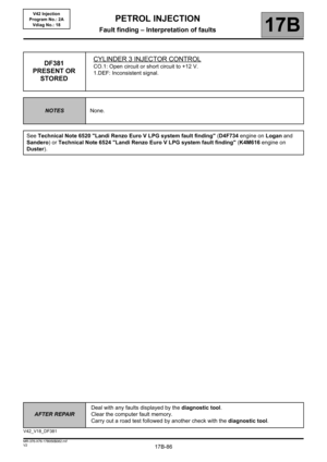
Fault finding – Interpretation of faults 17B - 21
Fault finding – Conformity check 17B - 160
Fault finding – Status summary table 17B - 161
Fault finding – Interpretation of statuses 17B - 163
Fault finding – Parameter summary table 17B - 180
Fault finding – Interpretation of parameters 17B - 183
Fault finding – Command summary table 17B - 213
Fault finding – Customer complaints 17B - 215
Fault finding – Fault Finding Chart 17B - 220
Fault finding – Test summary table 17B - 248
Fault finding – Tests 17B - 250
Page 2 of 279

17B-2V2 MR-376-X76-17B050$010.mif
17B
V42 Injection
Program No.: 2A
Vdiag No.: 04, 05, 06,
14, 16, 18
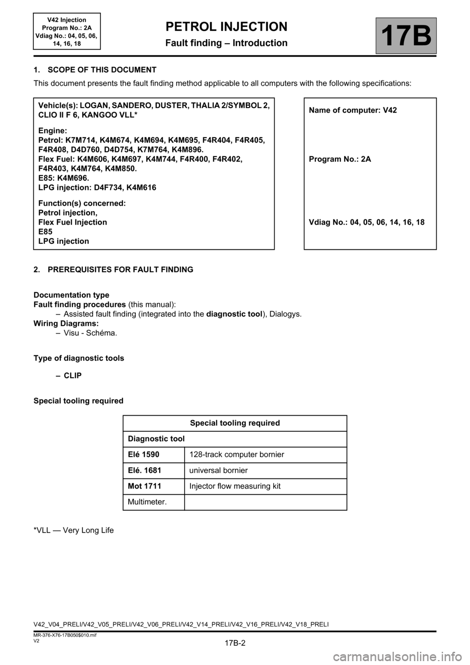
1. SCOPE OF THIS DOCUMENT
This document presents the fault finding method applicable to all computers with the following specifications:
2. PREREQUISITES FOR FAULT FINDING
Documentation type
Fault finding procedures (this manual):
– Assisted fault finding (integrated into the diagnostic tool), Dialogys.
Wiring Diagrams:
–Visu - Schéma.
Type of diagnostic tools
–CLIP
Special tooling required
*VLL — Very Long LifeVehicle(s): LOGAN, SANDERO, DUSTER, THALIA 2/SYMBOL 2,
CLIO II F 6, KANGOO VLL*Name of computer: V42
Engine:
Petrol: K7M714, K4M674, K4M694, K4M695, F4R404, F4R405,
F4R408, D4D760, D4D754, K7M764, K4M896.
Flex Fuel: K4M606, K4M697, K4M744, F4R400, F4R402,
F4R403, K4M764, K4M850.
E85: K4M696.
LPG injection: D4F734, K4M616Program No.: 2A
Function(s) concerned:
Petrol injection,
Flex Fuel Injection
E85
LPG injectionVdiag No.: 04, 05, 06, 14, 16, 18
Special tooling required
Diagnostic tool
Elé 1590128-track computer bornier
Elé. 1681universal bornier
Mot 1711Injector flow measuring kit
Multimeter.
V42_V04_PRELI/V42_V05_PRELI/V42_V06_PRELI/V42_V14_PRELI/V42_V16_PRELI/V42_V18_PRELI
PETROL INJECTION
Fault finding – Introduction
Page 3 of 279
17B-3V2 MR-376-X76-17B050$010.mif
PETROL INJECTION
Fault finding – Introduction17B
V42 Injection
Program No.: 2A
Vdiag No.: 04, 05, 06,
14, 16, 18
3. SAFETY INSTRUCTIONS
Safety rules must be observed during any work on a component to prevent any material damage or personal injury:
– Make sure the battery is properly charged to avoid damaging the computers if there is a low charge.
– Use the appropriate tools.
4. REMINDER
To run diagnostics on the vehicle computers, switch on the ignition using the key
To switch off the + after ignition feed, switch off the ignition using the key.
Page 4 of 279

17B-4V2 MR-376-X76-17B050$020.mif
17B
V42 Injection
Program No.: 2A
Vdiag No.: 04, 05, 06,
14, 16, 18
Injection computer:
The injection computer is located in the engine compartment, behind the battery.
TDC sensor:
This sensor is located on the gearbox casing, behind the engine.
Pinking sensor:
This sensor is located between the four injectors.
Refrigerant pressure sensor:
This sensor is located on the air conditioning circuit.
Injection coolant temperature sensor:
This sensor is located on the engine water chamber.
Injection air temperature sensor:
The air temperature sensor is located at the air circuit inlet.
Downstream oxygen sensor:
The downstream oxygen sensor is located on the exhaust pipe downstream of the catalytic converter.
Upstream oxygen sensor:
The upstream oxygen sensor is located on the exhaust pipe after the manifold.
Accelerator potentiometer:
The potentiometer is located on the accelerator pedal.
Brake light switch:
The switch is located on the brake pedal.
Injectors 1, 2, 3, 4:
The injectors are mounted on the engine.
Motorised throttle valve:
The damper valve is located in front of the inlet manifold.
Quadruple ignition coil module (D4D and K7M engines):
The coil module is located in the engine compartment.
Cylinder 1, 2, 3, 4 pencil coils (K4M engine):
They are located on the cylinder head.
Catalytic converter:
The catalytic converter is located on the exhaust pipe downstream of the catalytic pre-converter.
Fan unit relay:
The relay is located on the cooling radiator.
PETROL INJECTION
Fault finding – List and location of components
Page 5 of 279

17B-5V2 MR-376-X76-17B050$030.mif
17B
V42 Injection
Program No.: 2A
Vdiag No.: 04, 05, 06,
14, 16, 18
Injection computer:
The injection computer receives information from various sensors and sends control signals to various actuators
according to mappings that it has stored in the memory.
TDC sensor:
This sensor allows the computer to provide synchronisation as well as to know the position Top Dead Centre for
injection phasing.
Pinking sensor:
This sensor allows the computer to correct the ignition advance under high engine load to avoid damaging the
engine.
Refrigerant pressure sensor:
The role of the sensor is to measure the refrigerant fluid pressure in the air conditioning circuit.
Injection coolant temperature sensor:
The engine coolant temperature sensor informs the computer about the engine coolant temperature.
Injection air temperature sensor:
The air temperature sensor provides the computer with the temperature of air taken in by the engine.
Oxygen sensors:
The oxygen sensors allow the catalytic converter to correctly perform engine emission control tasks.
Accelerator potentiometer:
The potentiometer allows the computer to take into account driver requests expressed using the accelerator pedal.
Clutch pedal switch:
This switch allows the computer to convert to anti-jerking mode when the clutch pedal is depressed.
Brake light switch:
The brake light switch informs the computer of the brake pedal status.
Two gangs are used if the cruise control function exists.
Injectors:
These injectors enable rapid, precise metering of the quantity of fuel injected, with excellent injection process
repetitiveness.
PETROL INJECTION
Fault finding – Role of components
Page 6 of 279
17B-6V2 MR-376-X76-17B050$030.mif
PETROL INJECTION
Fault finding – Role of components17B
V42 Injection
Program No.: 2A
Vdiag No.: 04, 05, 06,
14, 16, 18
Motorised throttle valve:
The throttle valve allows engine air flow to be managed according to driver requests.
Quadruple ignition coil module (D4D and K7M engines):
The ignition unit enables ignition (explosion timing control).
Cylinder 1, 2, 3, 4 pencil coils (K4M engine):
The pencil coils enable ignition (explosion timing control).
Fan unit relay:
The engine cooling fan unit relay supplies power to the engine cooling fan.
Camshaft dephaser (F4R engine):
The function of the camshaft dephaser (VVT) is to vary the camshaft adjustment.
The system consists of a dephaser (hydraulic part that modifies the camshaft adjustment) and a solenoid valve.
Page 7 of 279
17B-7V2 MR-376-X76-17B050$040.mif
17B
V42 Injection
Program No.: 2A
Vdiag No.: 04, 05, 06,
14, 16, 18
For flex-fuel engines
1. Air filter
2. Motorised throttle valve
3. Injection air temperature sensor
4. Manifold pressure
5. Injectors
6. Ignition coils
7. Injection coolant temperature sensor
8. Pinking sensor
9. TDC sensor
10. Upstream oxygen sensors
11. Downstream oxygen sensors
12. Injection computer
13. Auxiliary cold starting system
14. Auxiliary fuel tank
15. Auxiliary fuel
16. Petrol/alcohol tank
17. Petrol pump
18. Bleed valve
PETROL INJECTION
Fault finding – Operating diagram
Page 8 of 279
17B-8V2 MR-376-X76-17B050$040.mif
PETROL INJECTION
Fault finding – Operating diagram17B
V42 Injection
Program No.: 2A
Vdiag No.: 04, 05, 06,
14, 16, 18
For petrol and bio-petrol engines
1. Air filter
2. Motorised throttle valve
3. Injection air temperature sensor
4. Manifold pressure
5. Injectors
6. Ignition coils
7. Injection coolant temperature sensor
8. Pinking sensor
9. TDC sensor
10. Upstream oxygen sensors
11. Downstream oxygen sensors
12. Injection computer
13. Petrol tank
14. Petrol pump
15. Bleed valve