Page 169 of 279

17B-169V2 MR-376-X76-17B050$110.mif
PETROL INJECTION
Fault finding – Interpretation of statuses17B
V42 Injection
Program No.: 2A
Vdiag No.: 04, 05, 06,
14, 16, 18
AFTER REPAIRDeal with any faults. Clear the faults from the computer memory.
Switch off the ignition and carry out a road test followed by a test with the diagnostic
tool.
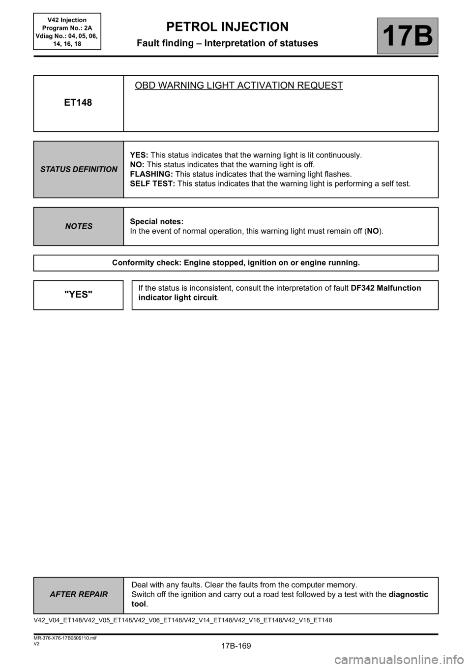
ET148OBD WARNING LIGHT ACTIVATION REQUEST
STATUS DEFINITIONYES: This status indicates that the warning light is lit continuously.
NO: This status indicates that the warning light is off.
FLASHING: This status indicates that the warning light flashes.
SELF TEST: This status indicates that the warning light is performing a self test.
NOTESSpecial notes:
In the event of normal operation, this warning light must remain off (NO).
Conformity check: Engine stopped, ignition on or engine running.
"YES"If the status is inconsistent, consult the interpretation of fault DF342 Malfunction
indicator light circuit.
V42_V04_ET148/V42_V05_ET148/V42_V06_ET148/V42_V14_ET148/V42_V16_ET148/V42_V18_ET148
Page 170 of 279

17B-170V2 MR-376-X76-17B050$110.mif
PETROL INJECTION
Fault finding – Interpretation of statuses17B
V42 Injection
Program No.: 2A
Vdiag No.: 04, 05, 06,
14, 16, 18
AFTER REPAIRDeal with any faults. Clear the faults from the computer memory.
Switch off the ignition and carry out a road test followed by a test with the diagnostic
tool.
ET321AIR CONDITIONING COMPRESSOR
STATUS DEFINITIONACTIVE: This status indicates that the air conditioning compressor is active.
INACTIVE: This status indicates that the air conditioning compressor is inactive
NOTESSpecial notes:
Only perform these tests if the status does not correspond with the system
programming functions.
Conformity check: Engine stopped, ignition on or engine running.
ACTIVETo check the operation of the air conditioning, run command AC180 Air
conditioning compressor relay control. In the event of a fault, apply the
interpretation of DF1072 Air conditioning compressor control.
V42_V04_ET321/V42_V05_ET321/V42_V06_ET321/V42_V14_ET321/V42_V16_ET321/V42_V18_ET321
Page 171 of 279

17B-171V2 MR-376-X76-17B050$110.mif
PETROL INJECTION
Fault finding – Interpretation of statuses17B
V42 Injection
Program No.: 2A
Vdiag No.: 04, 05, 06,
14, 16, 18
AFTER REPAIRDeal with any faults. Clear the faults from the computer memory.
Switch off the ignition and carry out a road test followed by a test with the diagnostic
tool.
ET405CLUTCH PEDAL SWITCH
STATUS DEFINITIONACTIVE: This status indicates that the clutch pedal is depressed.
INACTIVE: This status indicates that the clutch pedal is released.
NOTESSpecial notes:
Apply the checks only if statuses ACTIVE and INACTIVE are inconsistent
with the pedal position.
See the Wiring Diagrams Technical Note for Logan, Sandero, Duster, Thalia 2/
Symbol 2, Clio II F 6.
Conformity check: Engine stopped and ignition on, or engine running, and engine coolant temperature >
80°C.
INACTIVECheck the condition and fitting of the clutch pedal position sensor, component
code
675 (see MR 388 (Logan and Sandero), Mechanical, 37A, Mechanical
component controls, Clutch pedal position sensor: Removal - Refitting or MR
451 (Duster) or MR 423 (Thalia 2/Symbol 2), MR 430 (Clio II F 6), Mechanical,
37A, Mechanical component controls, Clutch pedal: Removal - Refitting).
Remove the clutch pedal position sensor, component code 675 (see MR 388
(Logan and Sandero), Mechanical, 37A, Mechanical component controls,
Clutch pedal position sensor: Removal - Refitting or MR 451 (Duster) or MR 423
(Thalia 2/Symbol 2), MR 430 (Clio II F 6), Mechanical, 37A, Mechanical
component controls, Clutch pedal: Removal - Refitting).
Check the insulation between connections MAM (for Logan, Sandero, Duster) or
M (for Thalia 2/Symbol 2, Clio II F 6) and 86D of component 675 with the switch in
the rest position.
– Repeat this operation with the switch pressed, and check the continuity and the
absence of interference resistance between the two connections.
If these 2 checks are not correct, replace the clutch pedal position sensor,
component code 675 (see MR 388 (Logan and Sandero), Mechanical, 37A,
Mechanical component controls, Clutch pedal position sensor: Removal -
Refitting or MR 451 (Duster) or MR 423 (Thalia 2/Symbol 2), MR 430 (Clio II F 6),
Mechanical, 37A, Mechanical component controls, Clutch pedal: Removal -
Refitting).
V42_V04_ET405/V42_V05_ET405/V42_V06_ET405/V42_V14_ET405/V42_V16_ET405/V42_V18_ET405
Page 172 of 279

17B-172V2 MR-376-X76-17B050$110.mif
PETROL INJECTION
Fault finding – Interpretation of statuses17B
V42 Injection
Program No.: 2A
Vdiag No.: 04, 05, 06,
14, 16, 18
AFTER REPAIRDeal with any faults. Clear the faults from the computer memory.
Switch off the ignition and carry out a road test followed by a test with the diagnostic
tool.
ET405
CONTINUED
INACTIVE
(CONTINUED)
Then check the continuity and absence of interference resistance of the following
connection:
–86D between components 120 and 675.
Check that the earth is correct on connection MAM (for Logan, Sandero, Duster) or
M (for Thalia 2/Symbol 2, Clio II F 6) of component 675.
If the connection(s) are faulty and there is a repair procedure (see Technical Note
6015A, Electrical wiring repair, Wiring: Precautions for repair), repair the
wiring, otherwise replace it.
ACTIVECheck the condition and fitting of the clutch pedal position sensor.
Remove the clutch pedal position sensor, component code 675 (see MR 388 (Logan
and Sandero), Mechanical, 37A, Mechanical component controls, Clutch pedal
position sensor: Removal - Refitting or MR 451 (Duster) or MR 423 (Thalia 2/
Symbol 2), MR 430 (Clio II F 6), Mechanical, 37A, Mechanical component
controls, Clutch pedal: Removal - Refitting) and check the insulation between
connections MAM and 86D of component 675 with the switch in the rest position.
– Repeat this operation with the switch pressed, and check the continuity and the
absence of interference resistance between the two connections.
If these 2 checks are not correct, replace the clutch pedal position sensor, component
code 675 (see MR 388 (Logan and Sandero) or 451 (Duster) and MR 423 (Thalia
2/Symbol 2), Mechanical, 37A, Mechanical component controls, Clutch pedal
position sensor: Removal - Refitting or MR 451 (Duster) or MR 423 (Thalia 2/
Symbol 2), MR 430 (Clio II F 6), Mechanical, 37A, Mechanical component
controls, Clutch pedal: Removal - Refitting).
Page 173 of 279
17B-173V2 MR-376-X76-17B050$110.mif
PETROL INJECTION
Fault finding – Interpretation of statuses17B
V42 Injection
Program No.: 2A
Vdiag No.: 04, 05, 06,
14, 16, 18
AFTER REPAIRDeal with any faults. Clear the faults from the computer memory.
Switch off the ignition and carry out a road test followed by a test with the diagnostic
tool.
ET673JAMMED ACCELERATOR PEDAL
STATUS DEFINITIONYES: This status indicates that the accelerator pedal is jammed.
NO: This status indicates that the accelerator pedal is not jammed.
NOTESTo reinitialise this status, clear the fault memory by running command RZ001 Fault
memory.
Conformity check: Engine stopped, ignition on or engine running.
YESCheck that the accelerator pedal is not jammed or that there is nothing impeding its
operation (floor carpet, etc.).
Check the brake switch (see the interpretation of fault DF050 Brake switch circuit.
V42_V04_ET673/V42_V05_ET673/V42_V06_ET673/V42_V14_ET673/V42_V16_ET673/V42_V18_ET673
Page 174 of 279
17B-174V2 MR-376-X76-17B050$110.mif
PETROL INJECTION
Fault finding – Interpretation of statuses17B
V42 Injection
Program No.: 2A
Vdiag No.: 04, 05, 06,
14, 16, 18
AFTER REPAIRDeal with any faults. Clear the faults from the computer memory.
Switch off the ignition and carry out a road test followed by a test with the diagnostic
tool.
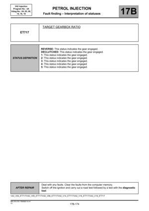
ET717TARGET GEARBOX RATIO
STATUS DEFINITIONREVERSE: This status indicates the gear engaged.
DECLUTCHED: This status indicates the gear engaged.
1: This status indicates the gear engaged.
2: This status indicates the gear engaged.
3: This status indicates the gear engaged.
4: This status indicates the gear engaged
5: This status indicates the gear engaged.
V42_V04_ET717/V42_V05_ET717/V42_V06_ET717/V42_V14_ET717/V42_V16_ET717/V42_V18_ET717
Page 175 of 279

17B-175V2 MR-376-X76-17B050$110.mif
PETROL INJECTION
Fault finding – Interpretation of statuses17B
V42 Injection
Program No.: 2A
Vdiag No.: 04, 05, 06,
14, 16, 18
AFTER REPAIRDeal with any faults. Clear the faults from the computer memory.
Switch off the ignition and carry out a road test followed by a test with the diagnostic
tool.
ET734
ET735
ET736HEATING RESISTOR NO.1 RELAY CONTROLHEATING RESISTOR NO.2 RELAY CONTROL
HEATING RESISTOR NO.3 RELAY CONTROL
STATUS DEFINITIONACTIVE: This status indicates that the relay is supplied.
INACTIVE: This status indicates that the relay is not supplied.
Conformity check: Engine stopped, ignition on or engine running.
INACTIVEStatuses ET734, ET735 and ET736 are INACTIVE with the ignition on and the engine
stopped, or when the engine is warm.
ACTIVEStatuses ET734, ET735 and ET736 are ACTIVE when the engine is started, the
engine coolant temperature is low (< 15°C) and the air temperature is low (<5°).
This program allows the engine coolant to be heated to enable the passenger
compartment to be heated.
To control the operation of the relays, run the following commands:
AC250 Heating resistor no.1 relay.
AC251 Heating resistor no.2 relay.
AC252 Heating resistor no.3 relay.
In the event of a fault, refer to the interpretation of faults:
DF992 Additional heater relay 1 circuit.
DF993 Additional heater relay 2 circuit.
DF994 Additional heater relay 3 circuit.
V42_V04_ET734/V42_V05_ET734/V42_V06_ET734/V42_V04_ET735/V42_V05_ET735/V42_V06_ET735/V42_V04_ET736/V42_V05_ET736/
V42_V06_ET736/V42_V14_ET734/V42_V14_ET735/V42_V14_ET736/V42_V16_ET734/V42_V16_ET735/V42_V16_ET736/V42_V18_ET734/
V42_V18_ET735/V42_V18_ET736
Page 176 of 279

17B-176V2 MR-376-X76-17B050$110.mif
PETROL INJECTION
Fault finding – Interpretation of statuses17B
V42 Injection
Program No.: 2A
Vdiag No.: 04, 05, 06,
14, 16, 18
AFTER REPAIRDeal with any faults. Clear the faults from the computer memory.
Switch off the ignition and carry out a road test followed by a test with the diagnostic
tool.
ET759BRAKING MULTIPLEX SIGNAL DETECTED
STATUS DEFINITIONABSENT: This status indicates that the braking multiplex signal detected is absent.
PRESENT: This status indicates that the braking multiplex signal detected is present.
INTERMEDIATE: This status indicates that the braking multiplex signal detected is
intermediate.
Conformity check: Engine stopped, ignition on or engine running.
Vehicle under + after ignition feed.
– Parking brake released,
– Gear lever in 1
st.
Neither the brake pedal nor the clutch pedal depressed.
Check status ET759.
PRESENT -
INTERMEDIATECheck the correct position and the conformity of the brake pedal sensor.
Run fault finding on the UCH domain (see 87B, UCH).
"ABSENT"The brake pedal sensor is correct.
V42_V04_ET759/V42_V05_ET759/V42_V06_ET759/V42_V14_ET759/V42_V16_ET759/V42_V18_ET759