Page 2 of 279

17B-2V2 MR-376-X76-17B050$010.mif
17B
V42 Injection
Program No.: 2A
Vdiag No.: 04, 05, 06,
14, 16, 18
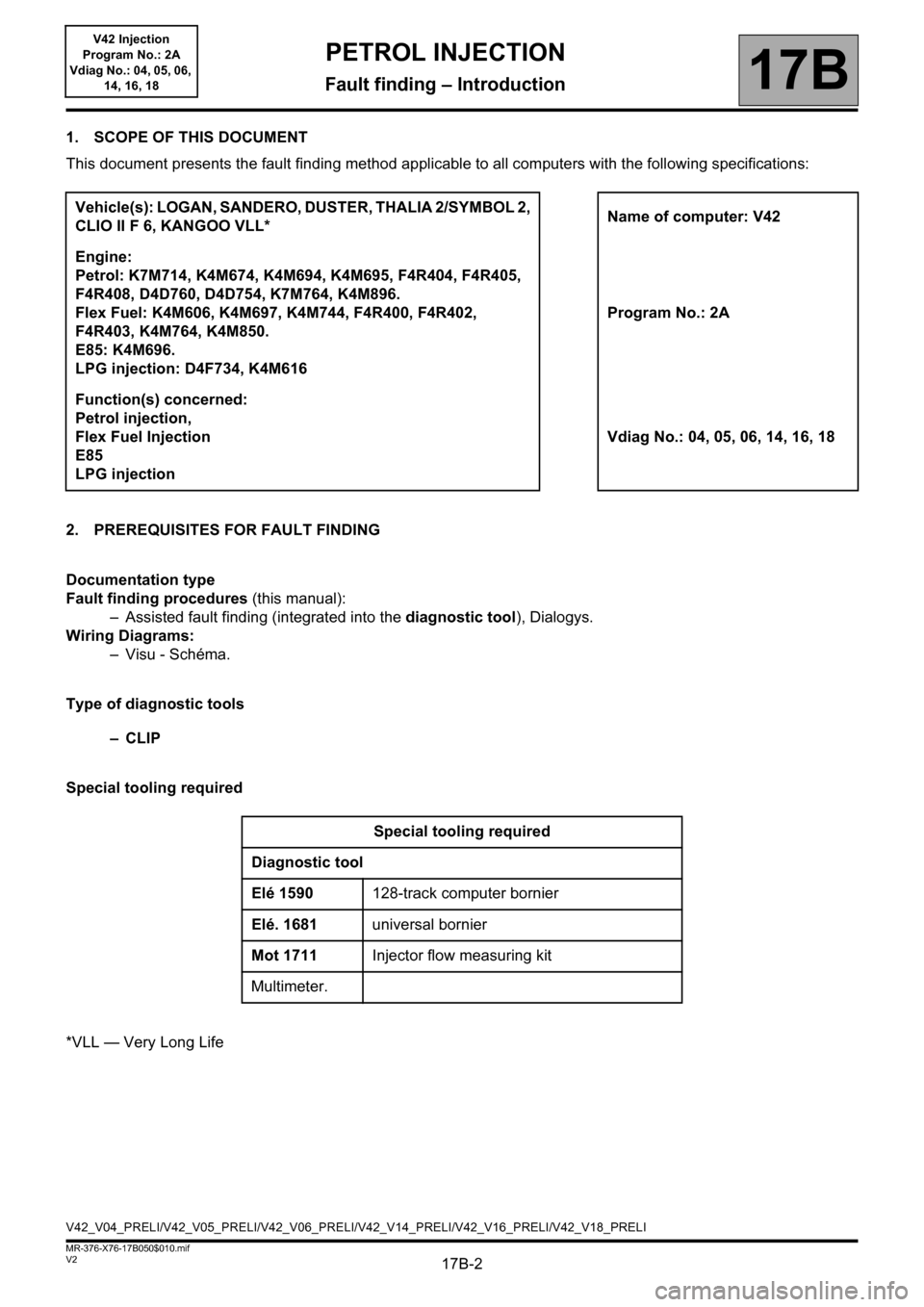
1. SCOPE OF THIS DOCUMENT
This document presents the fault finding method applicable to all computers with the following specifications:
2. PREREQUISITES FOR FAULT FINDING
Documentation type
Fault finding procedures (this manual):
– Assisted fault finding (integrated into the diagnostic tool), Dialogys.
Wiring Diagrams:
–Visu - Schéma.
Type of diagnostic tools
–CLIP
Special tooling required
*VLL — Very Long LifeVehicle(s): LOGAN, SANDERO, DUSTER, THALIA 2/SYMBOL 2,
CLIO II F 6, KANGOO VLL*Name of computer: V42
Engine:
Petrol: K7M714, K4M674, K4M694, K4M695, F4R404, F4R405,
F4R408, D4D760, D4D754, K7M764, K4M896.
Flex Fuel: K4M606, K4M697, K4M744, F4R400, F4R402,
F4R403, K4M764, K4M850.
E85: K4M696.
LPG injection: D4F734, K4M616Program No.: 2A
Function(s) concerned:
Petrol injection,
Flex Fuel Injection
E85
LPG injectionVdiag No.: 04, 05, 06, 14, 16, 18
Special tooling required
Diagnostic tool
Elé 1590128-track computer bornier
Elé. 1681universal bornier
Mot 1711Injector flow measuring kit
Multimeter.
V42_V04_PRELI/V42_V05_PRELI/V42_V06_PRELI/V42_V14_PRELI/V42_V16_PRELI/V42_V18_PRELI
PETROL INJECTION
Fault finding – Introduction
Page 9 of 279

17B-9V2 MR-376-X76-17B050$050.mif
17B
V42 Injection
Program No.: 2A
Vdiag No.: 04, 05, 06,
14, 16, 18
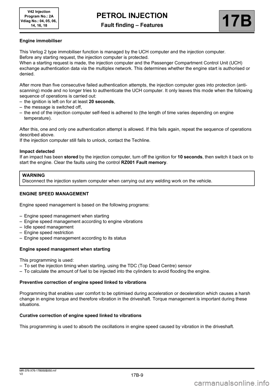
Engine immobiliser
This Verlog 2 type immobiliser function is managed by the UCH computer and the injection computer.
Before any starting request, the injection computer is protected.
When a starting request is made, the injection computer and the Passenger Compartment Control Unit (UCH)
exchange authentication data via the multiplex network. This determines whether the engine start is authorised or
denied.
After more than five consecutive failed authentication attempts, the injection computer goes into protection (anti-
scanning) mode and no longer tries to authenticate the UCH computer. It only leaves this mode when the following
sequence of operations is carried out:
– the ignition is left on for at least 20 seconds,
– the message is switched off,
– the end of the injection computer self-feed is adhered to (the length of time varies depending on engine
temperature).
After this, one and only one authentication attempt is allowed. If this fails again, repeat the sequence of operations
described above.
If the injection computer still fails to unlock, contact the Techline.
Impact detected
If an impact has been stored by the injection computer, turn off the ignition for 10 seconds, then switch it back on to
start the engine. Clear the faults using the control RZ001 Fault memory.
ENGINE SPEED MANAGEMENT
Engine speed management is based on the following programs:
– Engine speed management when starting
– Engine speed management according to engine vibrations
– Idle speed management
– Engine speed restriction
– Engine speed management according to its status
Engine speed management when starting
This programming is used:
– To set the injection timing when starting, using the TDC (Top Dead Centre) sensor
– To calculate the amount of fuel to be injected into the cylinders to avoid flooding the engine.
Preventive correction of engine speed linked to vibrations
Programming that enables user comfort to be optimised during acceleration or deceleration which causes a harsh
change in engine torque and therefore vibration in the driveshaft. Torque management is important during these
situations.
Curative correction of engine speed linked to vibrations
This programming is used to absorb the oscillations in engine speed caused by vibration in the driveshaft.WARNING
Disconnect the injection system computer when carrying out any welding work on the vehicle.
PETROL INJECTION
Fault finding – Features
Page 277 of 279

17B-277
AFTER REPAIRCarry out a road test, then check with the diagnostic tool.
V2 MR-376-X76-17B050$180.mif
PETROL INJECTION
Fault finding – Tests17B
V42 Injection
Program No.: 2A
Vdiag No.: 04, 05, 06,
14, 16, 18
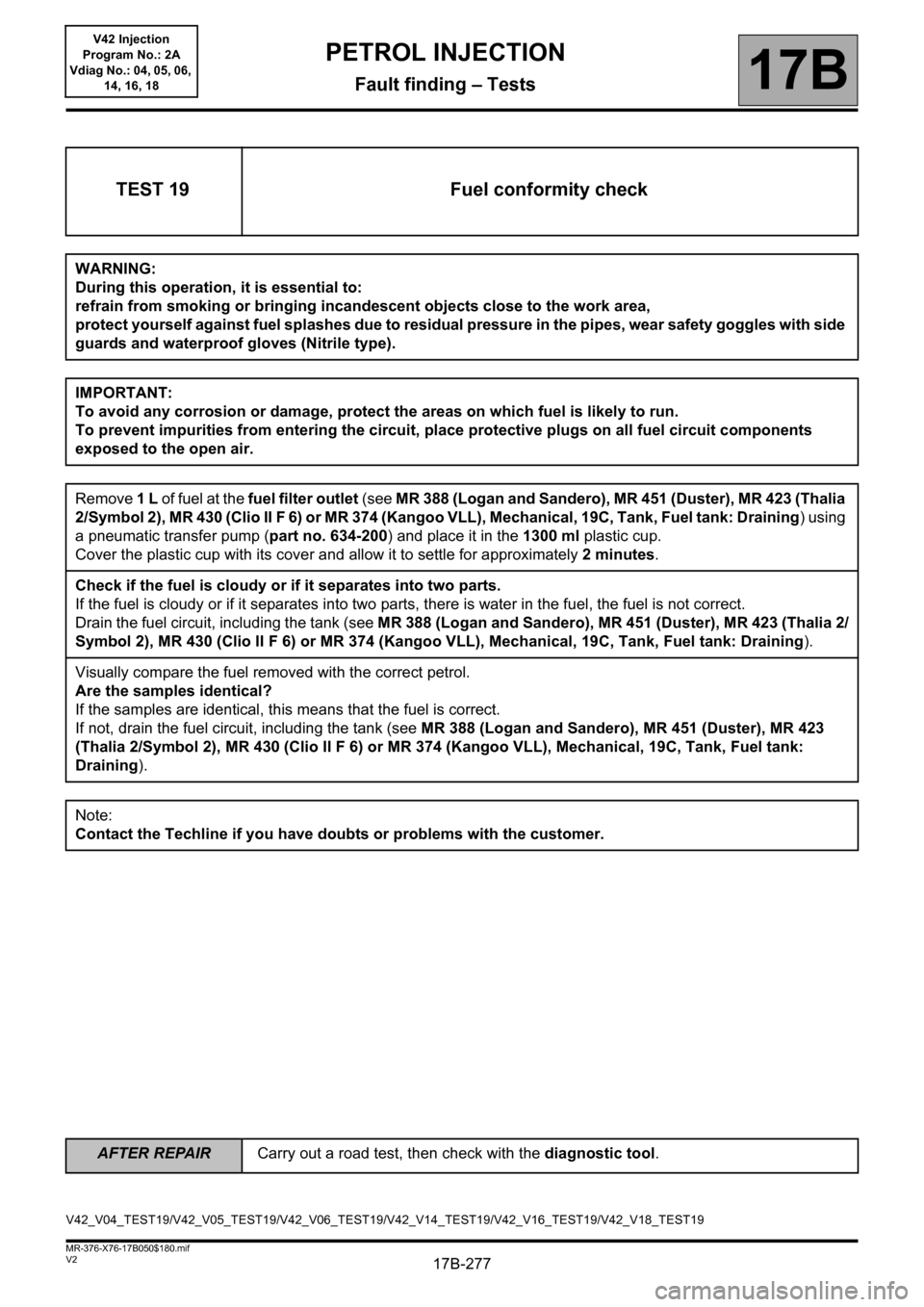
TEST 19 Fuel conformity check
WARNING:
During this operation, it is essential to:
refrain from smoking or bringing incandescent objects close to the work area,
protect yourself against fuel splashes due to residual pressure in the pipes, wear safety goggles with side
guards and waterproof gloves (Nitrile type).
IMPORTANT:
To avoid any corrosion or damage, protect the areas on which fuel is likely to run.
To prevent impurities from entering the circuit, place protective plugs on all fuel circuit components
exposed to the open air.
Remove 1 L of fuel at the fuel filter outlet (see MR 388 (Logan and Sandero), MR 451 (Duster), MR 423 (Thalia
2/Symbol 2), MR 430 (Clio II F 6) or MR 374 (Kangoo VLL), Mechanical, 19C, Tank, Fuel tank: Draining) using
a pneumatic transfer pump (part no. 634-200) and place it in the 1300 ml plastic cup.
Cover the plastic cup with its cover and allow it to settle for approximately 2 minutes.
Check if the fuel is cloudy or if it separates into two parts.
If the fuel is cloudy or if it separates into two parts, there is water in the fuel, the fuel is not correct.
Drain the fuel circuit, including the tank (see MR 388 (Logan and Sandero), MR 451 (Duster), MR 423 (Thalia 2/
Symbol 2), MR 430 (Clio II F 6) or MR 374 (Kangoo VLL), Mechanical, 19C, Tank, Fuel tank: Draining).
Visually compare the fuel removed with the correct petrol.
Are the samples identical?
If the samples are identical, this means that the fuel is correct.
If not, drain the fuel circuit, including the tank (see MR 388 (Logan and Sandero), MR 451 (Duster), MR 423
(Thalia 2/Symbol 2), MR 430 (Clio II F 6) or MR 374 (Kangoo VLL), Mechanical, 19C, Tank, Fuel tank:
Draining).
Note:
Contact the Techline if you have doubts or problems with the customer.
V42_V04_TEST19/V42_V05_TEST19/V42_V06_TEST19/V42_V14_TEST19/V42_V16_TEST19/V42_V18_TEST19