Page 377 of 416

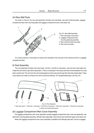
(4) Rear Wall Parts As shown in Fig.5-5, the rear wall assembly includes rear wall plate, rear wall reinforced plate, luggage
compartment door lock mounting plate and luggage compartment door cross beam etc.Fig. 5-5 Rear Wall Assembly
1. Rear wall upper cross beam
2. Luggage compartment lock
mounting plate big assembly
3. Rear wall left double-hole plate
4. Rear wall outer plate
Fig. 5-6 Roof Assembly
1. Roof outer panel 2. Roof No.1 cross beam 3. Roof No.2 cross beam 4.Roof rear cross beam 5.Roof No.3 cross beam
6. Moon roof reinforcement panel It is mainly used as a cross beam to improve the strength of the rear part of the vehicle and form a luggage
compartment door.5) Roof Assembly The roof assembly includes roof outer panel, roof No.1 and No.2 cross beam, and roof rear cross beam etc.
Inside the roof, there is top interior decoration. There is a heat pad in the center and there is bond between the cross
beam and the roof. The rain from the roof is discharged out of the rear part through the channels at both sides. These
cross beams are used to reinforce the roof's transverse stiffness. For disassembled parts, see Fig. 5-6.(6) Luggage Compartment Main Cover Assembly The luggage compartment main cover assembly includes luggage compartment main cover sub-assembly, rear
seat hook mounting plate assembly, left/right side angle plate, drip channel and reinforced upper cross beam etc.
When the luggage compartment main cover assembly is welded to the left/right side wall, it forms a luggageSurvey -Body Structure7-51 14432526143 2
Page 378 of 416

Fig. 5-7 Luggage Compartment Main
Cover Assembly
1. Luggage compartment main cover
2. Rear seat hook mounting plate assembly
3. Left/right side angle plate
4. Drip channelII. Movable Plate Work(1) Engine Hood & Front Fender The engine hood is used to protect the engine and fit the vehicle design. It is also helpful to the repair and
maintenance, and isolates the engine's noise. The engine hood has a double-lock device. The unlocking function
of the first locking is controlled by the cable handle under the instrument board. The unlocking function of the
second locking can raise the hood to a certain height. The double-lock function is designed in consideration of
safety. Especially when the vehicle is running at a high speed, it can prevent the engine hood from being raised,
which may cause traffic accident. The maximum angle at which the engine hood opens is 65°(See Fig.5-8).Fig. 5-7 Engine Hood & Front Fender
1. Engine hood
2. Hinge pin
3. Hinge support
4. Hinge
5.Inner hood panelSurvey -Body Structure7-642
3
51Max. opening angle less
than 65°compartment together with the rear floor and side walls. As shown in Fig. 5-7, a torsion resistant frame is also
formed at the rear part at the same time.3
4
213 2
Page 379 of 416

(2) Front FenderFront fender plays a role in front wheel apron and rotect person safty.And at the same tirne,if also woork as vehicle
styling parts.
For the match relationship between the front fender & engine hood and the front door, see Fig. 5-9.Fig. 5-9 Front Fender related to surrounding parts
A) With Engine Hood (4mm¡À1mm)
B) With Front Door (5mm¡À1mm)(3) Door Assembly Doors have LH/RH front door and rear door.
The door uses hinge gemel with limiting device, which is an open structure.
The door includes door outside plate, door inside plate, bumper and hinge reinforced plate etc.
The door has a complex structure, which is a movable component on the body. It helps the passengers get on/
off the vehicle and form an enclosed cabin with the main structure and the relevant parts. Meanwhile, the doors
are used frequently, so there is high requirement on their reliability and durability.
The outside/inside plate is molded by one complete steel sheet, which can improve the stiffness and precision.
In order to improve the safety when the vehicle is collided from the side, four doors are equipped with door
bumpers.
As shown in Fig. 5-10 and Fig. 5-11, the door assembly is made up of outside plate assembly and inside plate
assembly.Fig. 5-10 Front Door
1. Front door inner panel 2. Left front door inner reinforced panel 3. Front door window opper rail 4. Door lock reinforced panel
5. Left front door inner plate cross beam 6. Front door outer panel 7. Door bumper assembly
8. Front door upper hinge assembly 9. Front door lower hinge assembly 10. Hinge reinforced panel assemblySurvey -Body Structure7-7Engine hood
Front fenderFront door
Front fenderA
B12345678910
Page 380 of 416
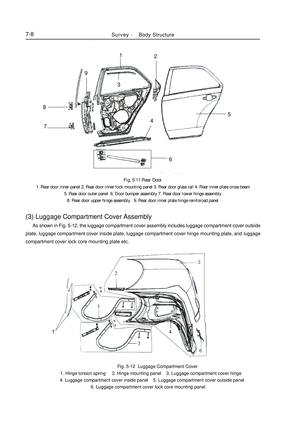
Fig. 5-11 Rear Door
1. Rear door inner panel 2. Rear door inner lock mounting panel 3. Rear door glass rail 4. Rear inner plate cross beam
5. Rear door outer panel 6. Door bumper assembly 7. Rear door lower hinge assembly
8. Rear door upper hinge assembly 9. Rear door inner plate hinge reinforced panel(3) Luggage Compartment Cover Assembly As shown in Fig. 5-12, the luggage compartment cover assembly includes luggage compartment cover outside
plate, luggage compartment cover inside plate, luggage compartment cover hinge mounting plate, and luggage
compartment cover lock core mounting plate etc. Fig. 5-12 Luggage Compartment Cover
1. Hinge torsion spring 2. Hinge mounting panel 3. Luggage compartment cover hinge
4. Luggage compartment cover inside panel 5. Luggage compartment cover outside panel
6. Luggage compartment cover lock core mounting panel1234568
79
1Survey -Body Structure7-8
Page 381 of 416

Chapter 2 Body RepairSection 1 Body Damage Forms and requirements For RepairI. Damage Type The damage type includes deformation, crack, rust-through, water leakage, dust leakage and the like caused
by collision, overload, fatigue, and corrosion.
The body damage is not merely caused by the huge force. As some parts (such as door etc.) are damaged, the
vehicle stays in an abnormal status, which also can cause damage. In most cases, the bend and torsion is caused
by huge local load in the impact or turnover accident.
Typical Body Damage:
1. Front Center Collision (Fig. 5-13)Fig. 5-13 Front Center CollisionBody Repair -Body Damage Forms and requirements For Repair7-9 For the damage caused by the collision on the front center, it usually makes the engine compartment front part
and the engine hood left/right side extend inwards so the following positions shall be checked:
a. Ambience of the left/right assembling position of the hood plate
b. Ambience of the joints of the front cross beam and the left/right longitudinal beam
2. Front External Force or Left External Force (Fig. 5-14)Fig. 5-14 Front External Force or Left External Force As shown in Fig. 5-14, when the front is pressed or the left side end is acted by the external force, the external
force will spread to around the front suspension mounting position from the left/right side of the hood, so
deformation occurs easily in this position.
Page 382 of 416

3. External Force Having an Angle with Vehicle Centerline (Fig. 5-15)Body Repair -Body Damage Forms and requirements For Repair7-10Fig. 5-15 External Force Having an Angle with Vehicle Centerline As shown in Fig. 5-15, when the vehicle is acted by an external force having an angle with its centerline, the
force will affect the hood root and the front window side post if it is strong enough.
4. Body Side Center Acted by External Force in Upright Direction (Fig. 5-16)Fig. 5-16 Body Side Center Acted by External Force in Upright Direction As shown in Fig. 5-16, when the body side center is acted by an external force in the upright direction, check
the following positions:
a. Front window side post upper/lower installation position;
b. Side window intermediate post upper/lower installation position;
c. Side window rear post deformation;
d. Roof and frame deformation.
When the body is acted by an external force on the rear part, its damage is the same as that caused by an external
force on the front part. Check the parts in full consideration of the rear structure and feature.External ForceExternal Force
Page 383 of 416

II. General Repair Principle1. Precaution
(a) Vehicle Protection
In the welding process, make sure to protect the paint, windshield,
seat and carpet with heat-resistant and fireproof covering.
(b) Safety Measures
(1)When pulling the body or crossbeam with drawing device, do
not stand at the position in the same line of the drawing cable,
and make sure to use safe drawing cable.
(2)Before repairing, make sure to check whether there is any
leakage. In case of any hole, remove it immediately.
(3)When welding near to the oil tank, make sure to remove the
oil tank first, and block the oil pipe.
(c) Protective Article
In the repairing process, make sure to wear uniforms, helmet and
safety shoes. In addition, according to the different work types,
wear proper gloves, welding mask, goggle, earplug, face cover,
and dust respirator etc. Wear the protective devices properly as
the table below.Body Repair -Body Damage Forms and requirements For Repair7-11Seat covering Windshield
coveringWrongWrongItem
Dust Respirator
Mask
Goggles
Safety Shoes
Welded Goggle
Earplug
Welded Mask
Welded Gloves Code
A
B
C
D
E
F
G
H
Page 384 of 416

III. Correct & Efficient Repair1. Removal
(a) Measure dimension before removal
Before removal and cutting operation, make measurement as
the body dimension drawings. Make sure to pull the damaged
body or crossbeam with drawing device.
(b) Cutting part
When working on the cutting part, make the cutting in a straight
position without reinforced plate.
(c) Boring/cutting precaution
In the boring or cutting operation, make sure whether there is
any oil pipe or cables etc on its back side, otherwise they may
be damaged.
(d) Removal of ambient components
When removing the ambient components, make sure to adhere
protective tape on the body and disassembly tool to prevent the
body or ambient components being damaged.
2. Installation Preparation
(a) Precaution
When the steel plate to be welded exceeds 3mm
thick, make hole-filling welding with MIG welder.
Tips: If the total thickness exceeds 3mm, the spot can not
provide adequate welding strength.7-12Cutting position
Reinforced plate
Bend positionWrongLarger than 3mmBody Repair -Body Damage Forms and requirements For Repair