Page 57 of 416
Section 2 Fuel Pump Inspection1. Fuel pump (1) Check whether the resistance of the fuel pump is 0.2~3.0 ohm¸ at 20°C. If not, replace the fuel pump (see Figure3-4).
(2) Fuel oil pump running:
Switch on the fuel pump with a battery and check. If the operation is unsatisfactory, replace the fuel pump or
wires (see Figure 3-5).
The test should be done within 10s to protect the coil from burning out.
2. Fuel injector assembly
Oil injecting quantity: 40~50cm3/s.
Tolerance of each injector: not more than 10 cm3.
If the fuel injecting quantity is not up to the specification, replace the injector.
Check leakage: Under above conditions, disconnect the wire from the battery, the fuel should not drip one per
minute.Figure 3-4 Figure 3-5BatteryOhm
meterFuel SystemFuel Pump Inspection3-16 -
Page 58 of 416
Section 3 Fuel Pump ReplacementComponent ViewFigure 3-6Replace1. Operations avoiding petrol overflowing.
2. Disconnect the fuel oil hose from the oil tank.
3. Disconnect the oil return hose from the oil tank.
4. Disconnect the vapor discharge pipe from the oil tank.
5. Remove the fuel oil pump assembly with a filter (see Figure 3-7)
Loosen the oil tank cap with a tailored tool. Take care not to bend
the arm of the oil quantity sensor when taking the fuel oil pump out
6. Mount the fuel oil pump assembly (see Figure 3-8).Replace the
sealing ring. Align the boss on the oil pump with the nick on the oil
tank port; tighten the oil tank cap with special tool.
Torque: 40N.m
7. Mount the vapor discharge pipe.
(1) Mount the oil return hose;
(2) Mount the fuel oil hose;
(3) Check leakage of the fuel oil.Figure 3-7
Figure 3-8Fuel SystemFuel Pump Replacement3-17Fuel tank cap
Fuel pump with fuel sensor as-
sembly
O-ring
Fuel tank assembly Fuel return hoseFuel oil hose
snap ring -
Page 59 of 416

Section 4 Fuel Emission Control SystemOn-board Inspection1. Check the operation when disconnecting the fuel supply.
(1) Warm the engine up to 2,500r/min at least, and check the noise of the injector with a sound level meter
(see Figure 3-9).
(2) When the throttle releases, the noise from the injector should stop immediately; repeat several times.
2. Check the fuel vapor discharge control system (see Figure 3-10).
(1) After starting the engine, disconnect the vacuum pipe.
(2) Make sure that there is vacuum present at the canister control valve (TEV) port when selecting ”ACTIVE
TEST" and "PURGE TEV" based on the display on the fault diagnosis instrument.
(3) After "ACTIVE TEST", connect the vacuum pipe.
(4) Carry out "ECM DATA MONITOR" on the fault diagnosis instrument, and then select "PURGE TEV"
for operation inspection.
(5) Start up the car after the engine warms up, and make sure the TEV ON from OFF (see Figure 3-11).
3. Check whether there is any distortion or damage on the filling cap and the washer (see Figure 3-12).Figure 3-9 Figure 3-10Fuel SystemFuel Emission Control System3-18Figure 3-11 Figure 3-12Sound level meter
Gasket -
Page 60 of 416

Section 5 Carbon Canister Replacement1. Check and replace the canister.
(1) Check for crack or damage on the canister visually (see Figure 3-13).
(2) Check the operation of the canister.
a. Plug the discharge port (see Figure 3-14).
b. Blow air (4.71KPa, 48kgf/cm2) into the absorption port when keeping the discharge port closed, and the
air should flow out from the exit port.
If the operation is unsatisfactory, replace the canister.
c.Blow air into the absorption port, the air should flow from other ports without any resistance.
If the operation is unsatisfactory, replace the canister.
(3) Clean the canister: Block the desorption port, blow air (4.71KPa, 48kgf/cm2) into the absorption port, and
the air should flow from the discharge port (see Figure 3-15).Fuel SystemCarbon Canister Replacement3-192. Canister control valve (TEV) (see Figure 3-16)
Mounting position: On the vacuum pipeline of the canister - suction manifold.
Faults: Bad idle speed, malfunction, etc.
General cause: Ingress of foreign materials into inside of the valve results in corrosion and Poor tightness.
Maintenance precautions: During maintenance:
1. Air flowing direction must conform to specifications;
2. If the control valve fails due to black particles in the valve body, and it is necessary to replace the control
valve, please check the condition of the canister;
3. Avoid liquid such as water and oil entering into the valve during maintaining as possible;
4. It is advisable to mount the canister control valve on the hose hanging in the air or fasten with soft rubber
to avoid transmission of solid borne noise.Figure 3-13Figure 3-15 Absorption port
Discharge port
Exit port
Plug upFigure 3-14Absorption port
Discharge port
Exit port -
Page 61 of 416
3. Vent valve (PCV) sub-assembly
Air should flow through the cylinder cap side freely.
Attention:
Do not suction air through the valve.
Never put anything into the valve. If the operation is unsatisfactory, replace PCV.
Blow air into from the suction side, and the air should be hard to flow through. If the operation is
unsatisfactory, replace PCV (see Figure 3-17).Figure 3-17Fuel SystemCarbon Canister Replacement3-20Figure 3-16 Easy measuring method: (disconnect the connector) Set the digital multi-meter to ohm position, with two leads
connecting to two pins of the canister control valve respectively, rated resistance 22-30 ohm at 20°CEasy HardCylinder head sideManifold side
Cleaning pipe -
Page 62 of 416

Chapter IV Exhaust SystemComponent View
Replace1. Remove the tail exhaust pipe assembly.
Remove 2 bolts and the tail exhaust pipe assembly.
2. Remove the middle exhaust pipe assembly.
Replace the exhaust system.
Remove 2 bolts and the middle exhaust pipe assembly.
3. Remove the front exhaust pipe assembly.
Remove 2 bolts and the front exhaust pipe assembly.
4. Mount the front exhaust pipe assembly.
Measure the free length of the spring with a slide caliper.
Free length: 42mmFigure 4-1
Figure 4-2Exhaust SystemExhaust System3-21Center Muffer
Front MufferRear MufferThree-way Catalytic ConverterRear Rubber
BracketFront Rubber Bracket Mount the front exhaust pipe on the exhaust manifold with new washer.
Notes:
Do not use the removed washer any more.
5. Mount the front exhaust pipe assembly.
Torque: 43N.m
6. Mount the middle exhaust pipe assembly.
Mount the middle exhaust pipe on the front exhaust pipe with new washer.
Torque: 44N.m
7. Mount the tail exhaust pipe assembly.
Mount the tail exhaust pipe on the middle exhaust pipe with new washer. (see Figure 4-2).
Torque: 43N.m
8. Check exhaust leakage.washer Tail pipe side Suitable for 1.5L/1.6L(Tight coupling)
Suitable for 1.3L/1.5L(Non-tight coupling) -
Page 63 of 416

2. Check the engine coolant quantity in the compensating tank.
The coolant level should be between LOW and FULL.
3. Check the coolant quality.
(1) Remove the radiator cover.
Do not remove the radiator cover when the engine and the radiator are still hot in order to avoid scalding
since the liquid vapor may inject.
(2) Check whether there are excessive deposit and rust or sundries around the radiator cover. The coolant is
not allowed to contact with oil.
(3) Remount the radiator cover.Chapter 5 Cooling SystemSection 1 System Inspection1. Check leakage in the cooling system (see Figure 5-1).
(1) Fill coolant in the radiator, and mount the tester at the radiator
cover port.
(2) Start the engine.
(3) Keep the pump pressure at 118KPa without drop. If the
pressure drops,check whether there is any leakage at the port,
radiator and water pump; if not, check the heating core,
cylinder and cap.Figure 5-1
Figure 5-2
Figure 5-3 Figure 5-4 (4) When the thermostat is at low temperature (lower than 77°C), the valve should close completely.Cooling SystemSystem Inspection3-224. Thermostat
Notes:
The temperature indicated on the thermostat is marked as open
temperature of the valve (see Figure 5-2).
(1) Submerge the thermostat into water and heat gradually.
(2) Check the open temperature of the valve.
Open temperature of the valve: 80-84°C
(3) Check the lift of the valve (see Figure 5-3 and Figure 5-4).
Lift of the valve: 8mm or more at 95°CTester of radiator cap
8.0mm or more -
Page 64 of 416

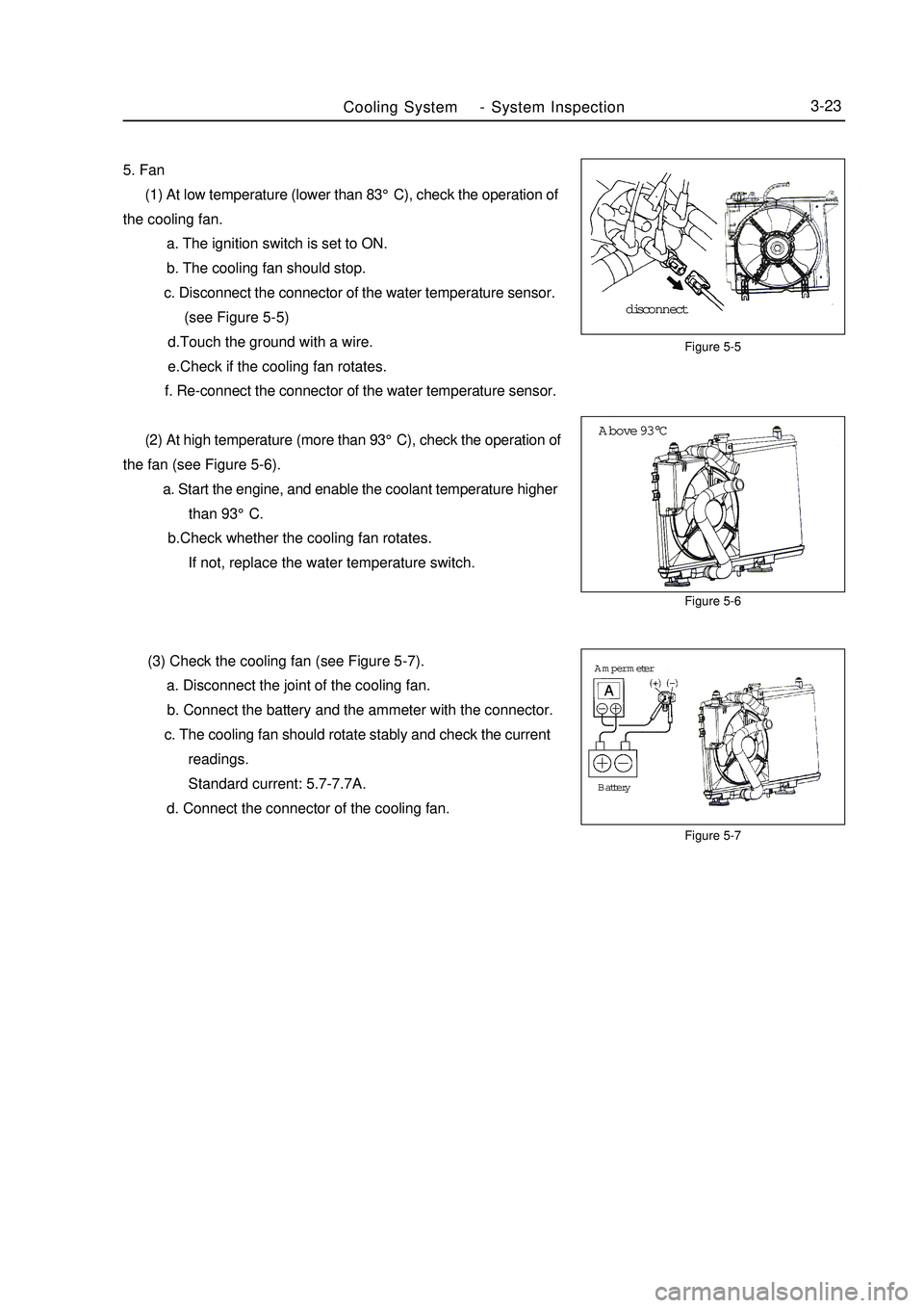
Figure 5-6
Figure 5-7Above 93°CFigure 5-5Cooling SystemSystem Inspection3-235. Fan
(1) At low temperature (lower than 83°C), check the operation of
the cooling fan.
a. The ignition switch is set to ON.
b. The cooling fan should stop.
c. Disconnect the connector of the water temperature sensor.
(see Figure 5-5)
d.Touch the ground with a wire.
e.Check if the cooling fan rotates.
f. Re-connect the connector of the water temperature sensor.
(2) At high temperature (more than 93°C), check the operation of
the fan (see Figure 5-6).
a. Start the engine, and enable the coolant temperature higher
than 93°C.
b.Check whether the cooling fan rotates.
If not, replace the water temperature switch.
(3) Check the cooling fan (see Figure 5-7).
a. Disconnect the joint of the cooling fan.
b. Connect the battery and the ammeter with the connector.
c. The cooling fan should rotate stably and check the current
readings.
Standard current: 5.7-7.7A.
d. Connect the connector of the cooling fan.disconnectBattery Amper meter -