Page 185 of 416

Brake System -Parking Brake System4-108Brake shoe baseboard
Parking brake shoe
Left positioning postRear Brake shoe
Shoe pad set spring cap
Rear brake shoe
Shoe pad set spring cap Shoe pad set springParking System Component
Replacement For left parking brake inhaul cable component, carry out the same steps as the right side.
1. Remove the accessories of the console. 6. Install the parking brake switch component.
Install the parking brake switch component with screw.
7. Install the accessories of the parking brake extension rod.
(1) Install the extension rod on the parking brake inhaul cable, and install #1 adjustment nut wire.
(2) Fasten the parking brake extension rod with two bolts.
Torque: 13N.m
(3) Connect the connector of the parking brake switch.
8. Install the accessories of the console.
9. Install the middle console.
10. Check the stroke of the parking brake extension rod.
11. Adjust the stroke of the parking brake extension rod.Shoe pad set spring
Brake drum Return spring Rear brake automatic adjustment
rod springLeft rear brake automatic
Adjustment rod
Page 186 of 416

Brake System -Parking Brake System4-1092. Remove the middle console.
3. Loosen #1 inhaul cable adjustment nut.
Remove #1 inhaul cable adjustment nut.
4. Remove the front floor extension rod.
Remove the two bolts to take out the front floor extension rod.
5. Remove the front exhaust pipe component.
6. Remove #2 front floor hot pad.
Remove the two bolts to take out the front floor hot pad.
7. Remove #3 parking brake inhaul cable component.
(1) Remove the four bolts to remove # 3 parking brake inhaul cable from the body.
(2) Remove #3 parking brake inhaul cable component from the parking brake balancer, and remove the inhaul
cable component.
8. Remove the rear wheel.
9. Remove the accessories of the brake drum.
10. Remove the front brake shoe.
11. Remove the left rear automatic adjustment rod.
12. Remove the rear brake shoe.
13. Remove parking brake inhaul cable component.
Remove the bolt, and remove parking brake inhaul cable
component from the baseboard.
14. Install parking brake inhaul cable component.
(1) Install parking brake inhaul cable component on the parking brake inhaul cable balancer.
(2) Fasten parking brake inhaul cable with four bolts.
Torque: 5.4N.m
Page 187 of 416
Brake System -Parking Brake System4-11015. Install #3 parking brake inhaul cable component.
Fasten #3 parking brake inhaul cable component to the baseboard.
Torque: 7.8N.m
16. Apply the heat-resistant lube.
17. Install the brake shoe.
18. Install the return spring of the brake shoe.
19. Install the left rear brake automatic adjustment rod.
20. Install the front brake shoe.
21. Check the installation of the brake drum.
22. Install the accessories of the brake drum.
23. Adjust the clearance of the brake shoe.
24. Install the rear wheel.
Torque: 103N.m
25. Fasten #1 adjustment nut wire temporarily.
Install #1 adjustment nut wire.
26. Install #2 front floor hot pad.
Fasten #2 floor hot pad with two bolts.
Torque: 5.5N.m
27. Install the front exhaust pipe component.
28. Install the front floor extension rod.
Install the front floor extension rod with two bolts.
29. Check the stroke of the parking brake extension rod.
30. Adjust the stroke of the parking brake extension rod.
Page 188 of 416

Part V Electric System & AccessoryChapter 1 Starting and Charging SystemSection 1 Starting System (MR479Q MR479QA MR481QA)I. Starter inspectionNote:
These tests must be completed within 5s, so as to prevent coil from burning out.
1. Electromagnetic switch testElectric System & Accessory-Starting and Charging System5-1 (1) As shown in the figure, use wire to connect starter.
(2) As shown in the figure, connect electromagnetic switch with
storage battery.
(3) Disconnect exciting coil from binding post A.
(4) Check whether clutch pinion moves outboard.
If clutch pinion does not move, replace electromagnetic switch.
(5) As shown above, connect battery, disconnect positive
pole (+) of battery from binding post, disengage
clutch pinion.
(6) Check whether clutch pinion returns.
If clutch pinion does not return, replace electromagnetic switch.
2. Starter no-load test
(1)Connect field coil and binding post.
(2) As shown in the figure, connect ammeter and battery
to starter.
(3) When check whether clutch pinion moves outwards, starter
should rotate slowly and smoothly.
(4) Check whether current reading of ammeter is normal or not.
Normal current: less than 90 A at 11. 5 V
If current is abnormal, replace starter.Ammeter Battery
Terminal 50
Terminal 30Disconnect
BatteryBatteryTerminal C
Terminal 50
Page 189 of 416
Starting and Charging System-
Starting System5-23. WiringII. Starter assembly replacement (MR479Q, MR479QA, MR481QA)1. Remove starter assembly
(1) Disconnect starter connector.
(2) Remove nuts, disconnect starter cable.
(3) Remove 2 bolts and starter assembly.
2. Install starter assembly
Installation should be conducted in reversed direction of removal
Torque:
Bolt 37N.m
Wire harness 9. 8N.m (1) Check that connecting wire between positive pole of storage battery and starter must be firm and reliable,
outside shroud must be in good condition, so as to prevent generating electric spark and causing fire.
(2) Check whether wire is conducted, whether sheath is broken, if wiring harness is damaged, replace wiring
harness.Please Refer to "MK WIRING DIAGRAM"
Page 190 of 416

Section 2 Charging system (MR479Q MR479QA MR481QA) 1- Danger of corrosion
The battery electrolyte is very corrosive. DO NOT overturn the battery.
2- Read the instructions for battery
3- Children are forbidden to touch the battery
4- Avoid fire, electromagnetic wave and strong light.
Avoid electric spark while repair; avoid short.
5- Wear protecting glasses
6- Danger of explosion
The explosive mixed gas will be produced while charging.
7- How to deal with a scrapped battery
The scrapped battery should be delivered to the collection station.
2. Battery removal and installation
Hint:
(1) The battery is not allowed to contact lubricating grease.
(2) The battery terminal is only allowed to be softly pulled out, in order to void damaging the battery.
Removal
(1) Remove the negative (-) ground cable
(2) Remove the battery positive (+) cable
(3) Loosen the fixing clamp on the battery.
Installation
Install according to the inverted order of removal.
Tighten the torque
Tighten the battery cable clip to 6N.
m
Tighten the fixing clamp to 12N.
mI. Battery Maintenance-free battery is applied in this vehicle. Its termination voltage is 12V. It is connected inline by six
2V single cell in tandem with walls between every pole.
1. Battery warning signsStarting and Charging System -Charging system5-3Be care of
sulfuric acidRead the
instructionAway from
childrenNo smoke Wear protective
glassesBe care of
explosion1234 56 7
Page 191 of 416

II. Charging system inspection1. Check battery working voltage
(1) After having driven the vehicle and in the case that 20 minutes
have not passed after having stopped the engine,turn the ignition
switch ON and turn on the electrical system (headlight,blower
motor) for 60 seconds to remove the surface charge.
(2) Turn the ignition switch OFF and turn off the electrical
systems. Then measure the battery voltage between the nega
tive and positive terminals of the battery.
Standard voltage: 12.5-12.9V at 20°C
Hint:
If the voltage is less than specification, charge the battery.
2. Check battery terminals, fuse box and fuse
(1) Check that the battery terminals are not loose or corroded.
(2) Check if fuse box and fuse for continuity.
3. Inspect drive belt
(1) Check the belt for excessive wear, frayed cords etc.
Hint:
If any defect has been found, replace the drive belt.
Cracks on the rib side of a belt are considered acceptable. If the
belt has chunks missing from the ribs, it should be replaced.
(2) Check that the belt fits properly in the ribbed grooves.
Hint:
Check with your hand to confirm that the belt has not slipped out
of the groove on the pulley.
4. Check alternator wiring
Check that the wiring is in good condition.Automobile Starting, Power Supply System -Charging system5-45. Listen for abnormal noises from alternator
Check that there is no abnormal noise from the alternator while the engine is running.
6. Inspect charge warning light circuit
Turn the ignition ON. Check that the charge warning light comes on. Start the engine. Check that the light
goes off.
Hint:
If the light does not work as normal, troubleshoot the charge warning light circuit.
Page 192 of 416

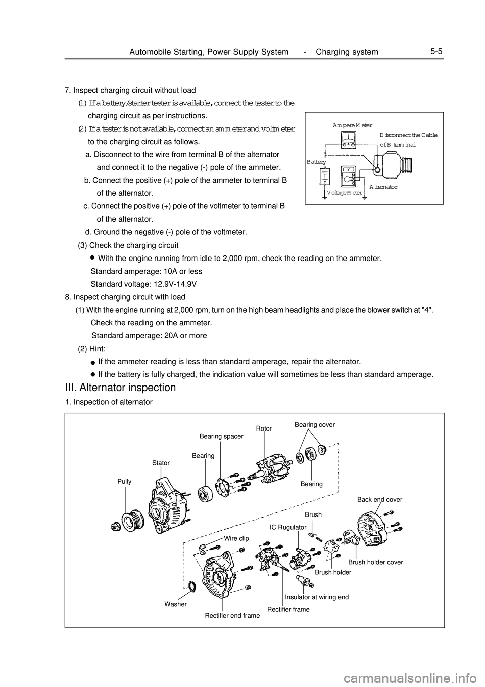
Automobile Starting, Power Supply System -Charging system5-57. Inspect charging circuit without load
(1) If a battery/starter tester is available, connect the tester to the
charging circuit as per instructions.
(2) If a tester is not available, connect an ammeter and voltmeter
to the charging circuit as follows.
a. Disconnect to the wire from terminal B of the alternator
and connect it to the negative (-) pole of the ammeter.
b. Connect the positive (+) pole of the ammeter to terminal B
of the alternator.
c. Connect the positive (+) pole of the voltmeter to terminal B
of the alternator.
d. Ground the negative (-) pole of the voltmeter.
(3) Check the charging circuit
With the engine running from idle to 2,000 rpm, check the reading on the ammeter.
Standard amperage: 10A or less
Standard voltage: 12.9V-14.9V
8. Inspect charging circuit with load
(1) With the engine running at 2,000 rpm, turn on the high beam headlights and place the blower switch at "4".
Check the reading on the ammeter.
Standard amperage: 20A or more
(2) Hint:
If the ammeter reading is less than standard amperage, repair the alternator.
If the battery is fully charged, the indication value will sometimes be less than standard amperage.III. Alternator inspection1. Inspection of alternatorPullyStatorBearingBearing spacerRotorBearing cover
Bearing
Wire clipBrush
Washer
Rectifier end frameRectifier frameInsulator at wiring endBrush holderBrush holder coverBack end coverIC RugulatorAmpere Meter
BatteryVoltage MeterAlternatorDisconnect the Cable
of B terminal