Page 257 of 416

1) Disconnect the positive (+) and negative (-) terminal cables from the battery and remove the battery from
the vehicle.Notice
Work must be started 60s after removal of the battery.Notice
When the connector is not connected, the terminals of the driver airbag assembly will be short circuited
automatically, preventing the airbag from being deployed unexpectedly. If the airbag is deployed unexpectedly,
the deployed surface should face up. It should be kept on a flat surface without any other items on it. 2) The airbag assembly shall be deployed according to the following procedures.
Driver airbag assembly
a. Remove the driver airbag assembly from the vehicle.
b. Prepare two 6m plus wire harnesses for deployment, connect
the other two ends to avoid unexpected deployment in case
of static electricity (see the figure below).Notice
The above-mentioned procedures can prevent the unexpected deployment due to static electricity and shall
therefore be performed strictly.Deployed Harness
Short Circuit Point
More than 6mInsulation tapeDeployment
wire harness
Short circuit
locationDriverÕs airbag
moduleAirbag assembly
Deployed
harness c. Touch the body of the vehicle with hands for static electricity elimination.
d. Cut off the wire harnesses of the driver airbag assembly and
connect them with the two wire harnesses for deployment,
and make sure to wrap up the connecting location with
insulating tape for insulation (see the figure on the right).
f. Pass the deployment wire harness of the driver airbag
assembly through an old tire with rim, and fix upwards the
driver airbag assembly by means of the wire connected to
the bolts, etc (see the figure on the right). e. Install the unused bolts to the inside bolt of the driver airbag assembly,and tie a thick metal wire securing
the wheel rim.5-70SRS (Supplemental Restraint System)-
SRS-General Information
Page 258 of 416
Used Tire Without
hub
Deployed HarnessDeployed Harness h. Try to disconnect at a location far away from the vehicle the
connector of the wire harness for deployment of the driver
airbag assembly, connect with the two terminals of the
battery removed from the vehicle and deploy the airbag
(see the figure on the right). g. Put three used tires without hubs onto the tire used to fix the
driver airbag assembly (see the figure on the right).
i. The deployed driver airbag assembly shall be scrapped according to the scrapping procedures.Notice
Make sure to deploy the driver airbag assembly when there is no person close by.
After the driver airbag is deployed, the gas generator is of high temperature. Keep it for over 30 minutes
until it gets cool for use.
If the driver airbag can't be deployed, please contact the Geely service station for help.5-71SRS (Supplemental Restraint System)-
SRS-General Information
Page 259 of 416

Item
Temperature regulation method
CompressorNominal refrigerating capacity / w
Displacement / (ml /r)
Model
Power consumed by magnetic clutch /W
Lubricating oil / ml
BlowerMaximum air quantity / (m3/h)
Air regulation
Motor power / W
Dimension /mm
Heat exchange quantity / W
Fan motor current / A
Fan motor revolution / (r/min)
Dimension /mm
Refrigerating capacity /W
Thermostatic expansion valve Condenser
Evaporator
Driving belt
Refrigerant filling amount/gChapter 7 Air Conditioning SystemSection 1 General InformationOverview:Air-conditioning system consists of refrigeration and heating parts. Refrigerating system mainly consists of
compressor, condenser and evaporator etc, it adsorbs heat in the air through circulation of refrigerant, so as to
reduce air temperature in car body and eliminate water vapour in air, to achieve the purpose of temperature drop
and dehumidification. Heating system mainly consists of heat exchanger and heater unit. It utilizes heat of engine
cooling water to heat air via heat exchanger, so as to achieve the purpose of heating. Regulation and control of
temperature, humidity and flow rate of air in car body is realized via heating and refrigeration systems separately
or jointly.
For parameters of refrigerating system, see the table:
Parameter
Control mixing of cool and warm air
4200
143 131
SEBX13 FM10S13
43
300001202/150ml cm3 420
Manual 4 speed
200
16 x 350 x 630
10000
8
2200
225 x 250 x 58
4000
Internal balance type 1. 5 tons of refrigeration
4PK820
440±20g 420±10g+20
05-72Air Conditioning System -
General Information
Page 260 of 416

5-73Precautions:1. Don't operate refrigerant in confined space or near open fire.
2. Always wear eyeglass.
3. Be careful don't let liquid refrigerant contact your eyes and skin,
if liquid refrigerant contacts your eye or skin.
(a) Please wash with fresh water.
Warning:
Don't knead your eyes or scrub your skin
(b) Apply soft petroleum ointment on your skin.
(c) See doctor or go to hospital immediately for specialized
treatment.
4. Don't heat container or put it near open fire.
5. Be careful not to fall off, object should not touch container.
6. If there is no sufficient refrigerant in refrigerating system, don't
operate the compressor.
If there is no sufficient refrigerant in the system, insufficient oil
lubrication might cause burning out of compressor. Be careful to
avoid occurrence of such things.
7. When compressor runs, don't turn on pressure gauge high-pressure
valve.
If high-pressure valve is turned on, refrigerant will flow in reverse
direction, and cause bursting of refrigerant tank, so only low
pressure valve may be turned on or off.
8. Be careful to avoid excess refrigerant
Excess refrigerant will result in poor refrigerating capacity, worse
fuel economical efficiency, engine overheat etc problems.Symptom
Blower does not workSymptom table Use the following table to find out the cause of fault, number indicates probable priority of problem, check each
part according to priority, replace components if required.
Suspected Area
1.Blower fuse
2.Centralized controller fuse
3. Blower relay
4. Integrated control panel assembly (blower switch)
5. Blower adjustment resistor
6. Blower
7. Wiring harness.Air Conditioning System -General Information
Page 261 of 416

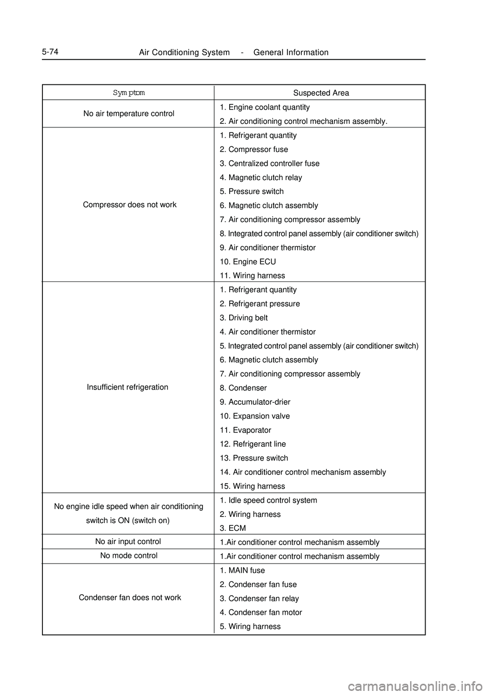
Air Conditioning System -General Information5-74Symptom
No air temperature control
Compressor does not work
Insufficient refrigeration
No engine idle speed when air conditioning
switch is ON (switch on)
No air input control
No mode control
Condenser fan does not workSuspected Area
1. Engine coolant quantity
2. Air conditioning control mechanism assembly.
1. Refrigerant quantity
2. Compressor fuse
3. Centralized controller fuse
4. Magnetic clutch relay
5. Pressure switch
6. Magnetic clutch assembly
7. Air conditioning compressor assembly
8. Integrated control panel assembly (air conditioner switch)
9. Air conditioner thermistor
10. Engine ECU
11. Wiring harness
1. Refrigerant quantity
2. Refrigerant pressure
3. Driving belt
4. Air conditioner thermistor
5. Integrated control panel assembly (air conditioner switch)
6. Magnetic clutch assembly
7. Air conditioning compressor assembly
8. Condenser
9. Accumulator-drier
10. Expansion valve
11. Evaporator
12. Refrigerant line
13. Pressure switch
14. Air conditioner control mechanism assembly
15. Wiring harness
1. Idle speed control system
2. Wiring harness
3. ECM
1.Air conditioner control mechanism assembly
1. MAIN fuse
2. Condenser fan fuse
3. Condenser fan relay
4. Condenser fan motor
5. Wiring harness
Page 262 of 416

Air Conditioning System -General Information5-75Air conditioner pressure switch plug-in unitInspection1. Check pressure switch
(a) Magnetic clutch control:
Check operation of pressure switch
( 1 ) Install manifold instrument
( 2 ) Connect positive meter pen of ohmmeter to terminal 4,
negative meter pen to terminal 1respectively.
( 3 ) As shown in the figure, check connection of each terminal
when refrigerant pressure changes
If operation does not conform to specification, replace
pressure switch.
(b) Check operation of condenser fan
( 1 ) Connect positive meter pen to terminal 2, negative meter pen to terminal 3 respectively.
( 2 ) As shown in the figure, check connection of each terminal when refrigerant pressure changes
If operation does not conform to specification, replace pressure switch.
2. Compressor magnetic clutch
(a) Connect positive pole of storage battery to binding post, negative pole to compressor shell.
(b) Check magnetic clutch in energized condition.
If abnormal, replace magnetic clutch.
3. Air conditioner thermistorThermistor plug-in unit (a) As shown in the figure, check resistance value of air conditioner thermistor
between terminal 1, 2 at each temperature,
Resistance:1
2Temperature(°C)Resistance
(K ohm)
Page 263 of 416

Condition/ circuit Tester connection Specification
OFF OFF
LO E D1 ON
ML E D1 D2 ON
MH E D1 D4 ON
HI E D1 D5 ONBlower switch connector unitD2 D4 D5
D1 D6 E4. Integrated control panel assembly
(a) Check connection of blower switch. If connection does not conform to specification, replace integrated control panel assembly.
(b) Check lighting operation
Connect positive wire of storage battery to terminal D6, negative wire to terminal E, then check whether
illuminating lamp illuminates. If bulb does not illuminate, replace the bulb.
(c) Check connection of air conditioning switch
As shown in the table, check connection of terminal when switch is pressedA/C switch connectorTester connection Specification
2 5 ON If connection does not conform to specification, replace air
conditioning switch.
(d) Check indicator work
Connect positive wire of storage battery to terminal 1, negative
wire to terminal 3, then check whether illuminating lamp
illuminates.
If connection does not conform to specification, replace
integrated control panel assembly.
4. Blower adjustment resistor
(a) Measure resistance between terminals, as shown in the table
Tester connection Specification
1-2 About 0. 38 Ohm
2-3 About 1. 47 Ohm
1-4 About 2. 71 OhmSpeed regulating resistance connector unit If resistance does not conform to specification, replace blower
resistance.
5. Blower assembly
(a) Connect positive wire of storage battery to terminal 2, negative
wire to terminal 1, check work smoothness of motor.
If work does not conform to specification, replace blower
assembly5-76Air Conditioning System -General Information
Page 264 of 416
5-776. Heater blower motor relay assembly
Check connection of relayHeater blower motor relay assembly3
21
4 If connection does not conform to specification, replace heater
blower motor relay.
7. Magnetic clutch relay
(a)Check connection of relay
If connection does not conform to specification, replace
magnetic clutch relayCondition Tester connection Specification
Constant1 2 ON
3 4 ON Apply storage battery
positive voltage
between terminal 1, 2Condition Tester connection Specification
Constant
1 2 ON
3 5 ON Apply storage battery
positive voltage be-
tween terminal 1, 2Magnetic clutch relayAir Conditioning System -General Information