Page 54 of 416

Dismounting/mounting and disassembly and assembly (see Figure 2-1~2-5).
1. Drain the coolant.
Warning: Do not remove the radiator cover, liquid under pressure or steam (likely to eject) while the engine
and the radiator are still hot in order to avoid scalding.
(1) Remove the radiator cover.
(2) Remove the plug of the radiator, and discharge the coolant.
2. Remove the cable of the accelerator.
Release the nut and remove the cable of the accelerator.
3. Remove the air filter hood with hose.
(1) Disconnect the connector and the wire fastening device of the suction temperature sensor.
(2) Disconnect the vent duct from the air filter hose.
(3) Release the clamping collar bolt of the air filter hose.
(4) Release 2 clamps on the air filter hood.
(5) Disconnect the air filter hose from the throttle body, and remove the air filter hood together with the hose.Figure 2-6
Figure 2-7
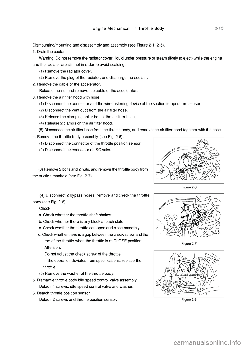
Figure 2-8Engine MechanicalThrottle Body3-134. Remove the throttle body assembly (see Fig. 2-6).
(1) Disconnect the connector of the throttle position sensor.
(2) Disconnect the connector of ISC valve.
(3) Remove 2 bolts and 2 nuts, and remove the throttle body from
the suction manifold (see Fig. 2-7).
(4) Disconnect 2 bypass hoses, remove and check the throttle
body (see Fig. 2-8).
Check:
a. Check whether the throttle shaft shakes.
b. Check whether there is any block at each state.
c. Check whether the throttle can open and close smoothly.
d. Check whether there is a gap between the check screw and the
rod of the throttle when the throttle is at CLOSE position.
Attention:
Do not adjust the check screw of the throttle.
If the operation deviates from specifications, replace the
throttle.
(5) Remove the washer of the throttle body.
5. Dismantle throttle body idle speed control valve assembly.
Detach 4 screws, idle speed control valve and washer.
6. Detach throttle position sensor
Detach 2 screws and throttle position sensor.Coolant Bypass Pipe -
Page 378 of 416

Fig. 5-7 Luggage Compartment Main
Cover Assembly
1. Luggage compartment main cover
2. Rear seat hook mounting plate assembly
3. Left/right side angle plate
4. Drip channelII. Movable Plate Work(1) Engine Hood & Front Fender The engine hood is used to protect the engine and fit the vehicle design. It is also helpful to the repair and
maintenance, and isolates the engine's noise. The engine hood has a double-lock device. The unlocking function
of the first locking is controlled by the cable handle under the instrument board. The unlocking function of the
second locking can raise the hood to a certain height. The double-lock function is designed in consideration of
safety. Especially when the vehicle is running at a high speed, it can prevent the engine hood from being raised,
which may cause traffic accident. The maximum angle at which the engine hood opens is 65°(See Fig.5-8).Fig. 5-7 Engine Hood & Front Fender
1. Engine hood
2. Hinge pin
3. Hinge support
4. Hinge
5.Inner hood panelSurvey -Body Structure7-642
3
51Max. opening angle less
than 65°compartment together with the rear floor and side walls. As shown in Fig. 5-7, a torsion resistant frame is also
formed at the rear part at the same time.3
4
213 2
Page 379 of 416

(2) Front FenderFront fender plays a role in front wheel apron and rotect person safty.And at the same tirne,if also woork as vehicle
styling parts.
For the match relationship between the front fender & engine hood and the front door, see Fig. 5-9.Fig. 5-9 Front Fender related to surrounding parts
A) With Engine Hood (4mm¡À1mm)
B) With Front Door (5mm¡À1mm)(3) Door Assembly Doors have LH/RH front door and rear door.
The door uses hinge gemel with limiting device, which is an open structure.
The door includes door outside plate, door inside plate, bumper and hinge reinforced plate etc.
The door has a complex structure, which is a movable component on the body. It helps the passengers get on/
off the vehicle and form an enclosed cabin with the main structure and the relevant parts. Meanwhile, the doors
are used frequently, so there is high requirement on their reliability and durability.
The outside/inside plate is molded by one complete steel sheet, which can improve the stiffness and precision.
In order to improve the safety when the vehicle is collided from the side, four doors are equipped with door
bumpers.
As shown in Fig. 5-10 and Fig. 5-11, the door assembly is made up of outside plate assembly and inside plate
assembly.Fig. 5-10 Front Door
1. Front door inner panel 2. Left front door inner reinforced panel 3. Front door window opper rail 4. Door lock reinforced panel
5. Left front door inner plate cross beam 6. Front door outer panel 7. Door bumper assembly
8. Front door upper hinge assembly 9. Front door lower hinge assembly 10. Hinge reinforced panel assemblySurvey -Body Structure7-7Engine hood
Front fenderFront door
Front fenderA
B12345678910