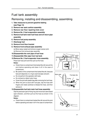
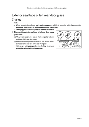
Page 17 of 419
Note: *1 Indicating that check valve noise and engine vibration condition, and adjust them if necessary.*2 It is suggested that see operating modes on page 116 of operating instruction to perform.*3 Indicating that check once every 20000km or 12 moths after 80000km or 48 months.*4 Indicating that check water tank and condenser are blocked by leaves, dust or insects, and clean
hose connections.*5 Replace at initial 60000km, and replace every 30000km in future.*6 Only “Geely genuine ultra-long engine coolant” or equivalent high-quality ethylene glycol engine
coolant without silicate, amines, nitrite, borate and with long-life compound organic acid technology
are allowed to use, and coolant should be repeated several times until it is filled up.*7 Indicating that check once every 20000km or 12 moths after 80000km or 48 months.Maintenance period-Table on maintenance period at normal conditions 6
Page 18 of 419

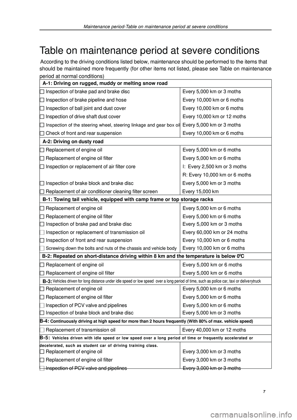
Maintenance period-Table on maintenance period at severe conditionsTable on maintenance period at severe conditionsAccording to the driving conditions listed below, maintenance should be performed to the items that
should be maintained more frequently (for other items not listed, please see Table on maintenance
period at normal conditions) 7 A-1: Driving on rugged, muddy or melting snow road Inspection of brake pad and brake disc Every 5,000 km or 3 moths Inspection of brake pipeline and hose Every 10,000 km or 6 moths Inspection of ball joint and dust cover Every 10,000 km or 6 moths Inspection of drive shaft dust cover Every 10,000 km or 12 moths Inspection of the steering wheel, steering linkage and gear box oilEvery 5,000 km or 3 moths Check of front and rear suspension Every 10,000 km or 6 moths
A-2: Driving on dusty road Replacement of engine oil Every 5,000 km or 6 moths Replacement of engine oil filter Every 5,000 km or 6 moths Inspection or replacement of air filter core I: Every 2,500 km or 3 moths
R: Every 10,000 km or 6 moths Inspection of brake block and brake disc Every 5,000 km or 3 moths Replacement of air conditioner cleaning filter screen Every 15,000 km
B-1: Towing tail vehicle, equipped with camp frame or top storage racks Replacement of engine oil Every 5,000 km or 6 moths Replacement of engine oil filter Every 5,000 km or 6 moths Inspection of brake pad and brake disc Every 5,000 km or 3 moths Inspection or replacement of transmission oil Every 60,000 km or 24 moths Inspection of front and rear suspension Every 10,000 km or 6 moths Screwing down the bolts and nuts of the chassis and vehicle bodyEvery 10,000 km or 6 moths
B-2: Repeated on short-distance driving within 8 km and the temperature is below 0 °C Replacement of engine oil Every 5,000 km or 6 moths Replacement of engine oil filter Every 5,000 km or 6 moths
B-3: Vehicles driven for long distance under idle speed or low speed over a long period of time, such as police car, taxi or deliverytruck. Replacement of engine oil Every 5,000 km or 6 moths Replacement of engine oil filter Every 5,000 km or 6 moths Inspection of PCV valve and pipelines Every 5,000 km or 6 moths Inspection of brake block and brake disc Every 5,000 km or 3 moths
B-4: Continuously driving at high speed for more than 2 hours frequently (With 80% of max. vehicle speed) Replacement of transmission oil Every 40,000 km or 12 moths
B-5: Vehicles driven with idle speed or low speed over a long period of time or frequently accelerated or
decelerated, such as student car of driving training class. Replacement of engine oil Every 3,000 km or 3 moths Replacement of engine oil filter Every 3,000 km or 3 moths Inspection of PCV valve and pipelines Every 3,000 km or 3 moths
Page 19 of 419

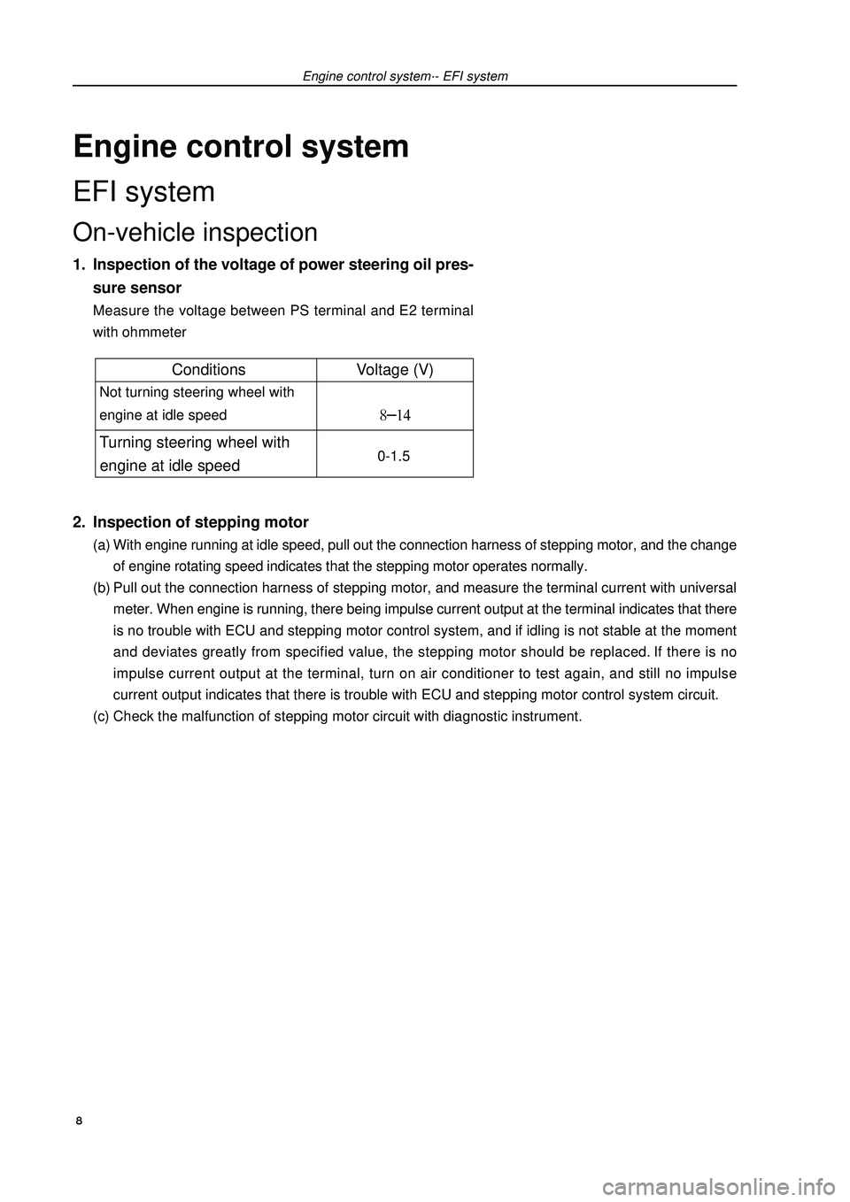
Engine control systemEFI systemOn-vehicle inspection1. Inspection of the voltage of power steering oil pres-
sure sensorMeasure the voltage between PS terminal and E2 terminal
with ohmmeter2. Inspection of stepping motor(a) With engine running at idle speed, pull out the connection harness of stepping motor, and the change
of engine rotating speed indicates that the stepping motor operates normally.
(b) Pull out the connection harness of stepping motor, and measure the terminal current with universal
meter. When engine is running, there being impulse current output at the terminal indicates that there
is no trouble with ECU and stepping motor control system, and if idling is not stable at the moment
and deviates greatly from specified value, the stepping motor should be replaced. If there is no
impulse current output at the terminal, turn on air conditioner to test again, and still no impulse
current output indicates that there is trouble with ECU and stepping motor control system circuit.
(c) Check the malfunction of stepping motor circuit with diagnostic instrument.Engine control system·- EFI system 8Conditions Voltage (V) Not turning steering wheel with
engine at idle speed Turning steering wheel with
engine at idle speed 0-1.5
Page 20 of 419

Engine control system·- EFI systemInspection1. VVT control solenoid valve assembly (4G18-1006200)(a) Resistance inspection
(1) Measure the resistance between terminals with ohmmeter
Resistance: (b) Operation inspection
Connect battery positive (+) wire to No.1 terminal and negative (-) wire to No. 2 terminal, and check
valve operation.
Note: ensure that the valve is not stuck.
Hint: if there are foreign matters in the valve, the valve could not be closed tightly and will
thus result in slight pressure being lifted toward higher direction.2. Throttle body components (4G18-1001240)(a) Inspection of throttle body
(1) Throttle valve shaft should not swing.
(2) All channels should not be blocked.
(3) Throttle valve plate should rotate flexibly and act smoothly.
(4) When the throttle is at closed position, there should be no clearance between throttle stop bolts and
throttle lever.
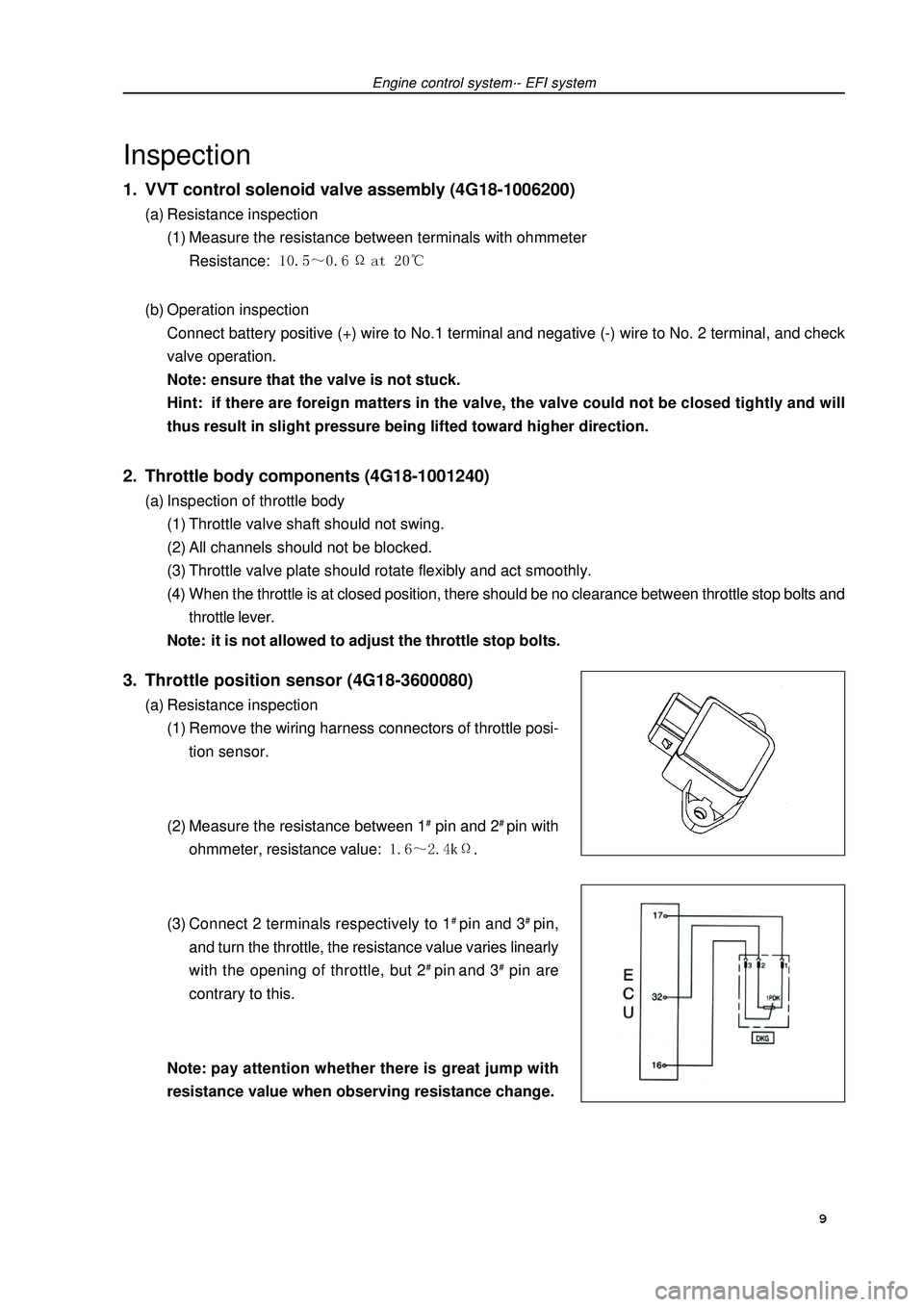
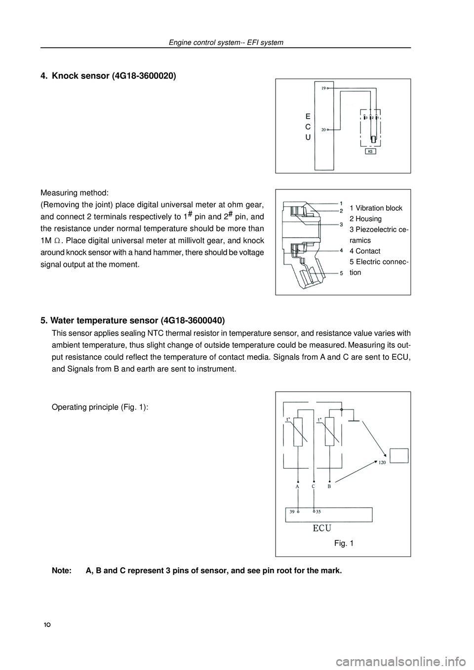
Note: it is not allowed to adjust the throttle stop bolts.3. Throttle position sensor (4G18-3600080)(a) Resistance inspection
(1) Remove the wiring harness connectors of throttle posi-
tion sensor.
(2) Measure the resistance between 1# pin and 2# pin with
ohmmeter, resistance value: .
(3) Connect 2 terminals respectively to 1# pin and 3# pin,
and turn the throttle, the resistance value varies linearly
with the opening of throttle, but 2# pin and 3# pin are
contrary to this.
Note:pay attention whether there is great jump with
resistance value when observing resistance change. 9
Page 21 of 419

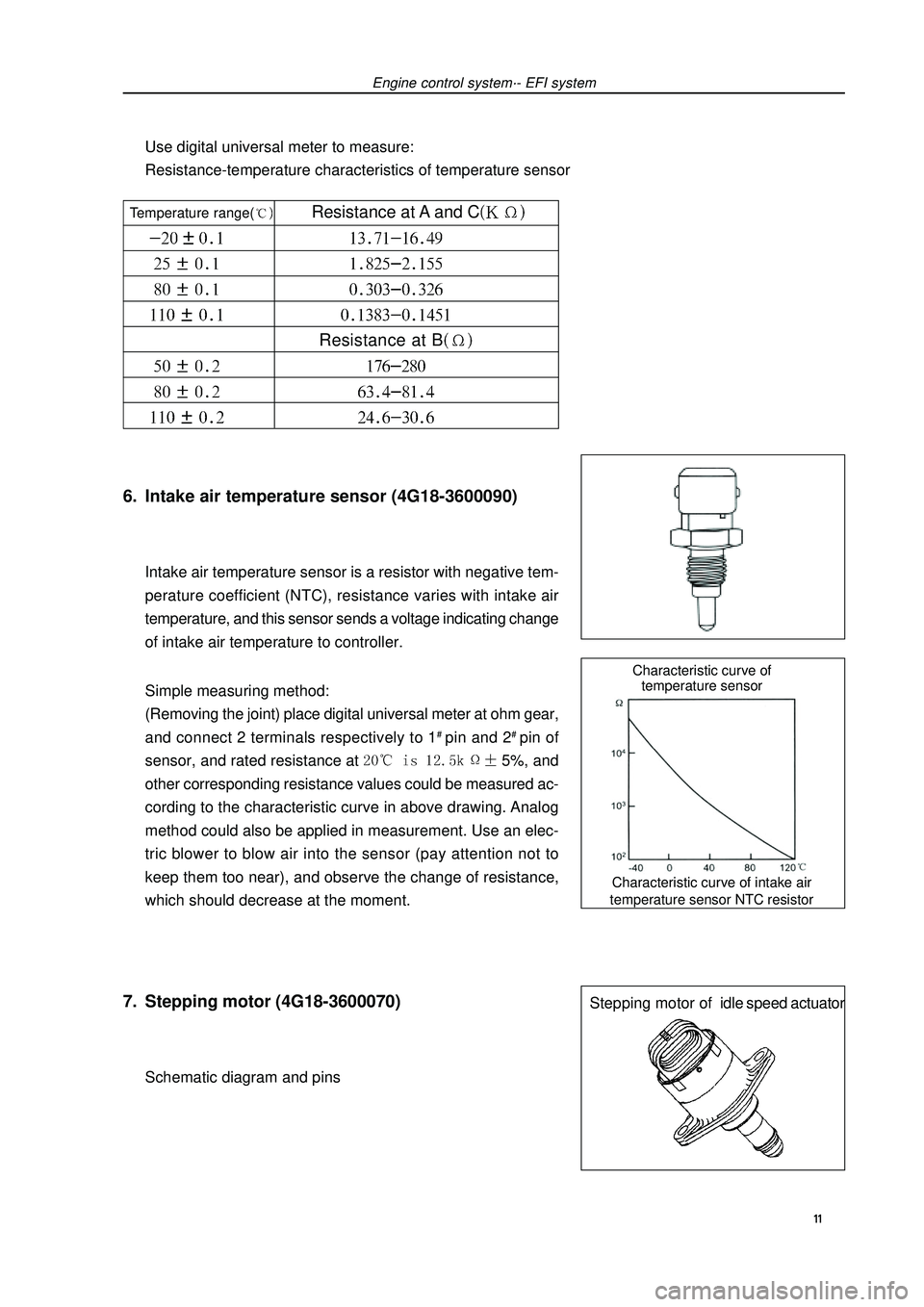
5. Water temperature sensor (4G18-3600040)This sensor applies sealing NTC thermal resistor in temperature sensor, and resistance value varies with
ambient temperature, thus slight change of outside temperature could be measured. Measuring its out-
put resistance could reflect the temperature of contact media. Signals from A and C are sent to ECU,
and Signals from B and earth are sent to instrument.
Operating principle (Fig. 1):
Note: A, B and C represent 3 pins of sensor, and see pin root for the mark. Measuring method:
(Removing the joint) place digital universal meter at ohm gear,
and connect 2 terminals respectively to 1#
pin and 2#
pin, and
the resistance under normal temperature should be more than
1M. Place digital universal meter at millivolt gear, and knock
around knock sensor with a hand hammer, there should be voltage
signal output at the moment.Engine control system·- EFI systemFig. 11 Vibration block
2 Housing
3 Piezoelectric ce-
ramics
4 Contact
5 Electric connec-
tion4. Knock sensor (4G18-3600020) 10
Page 22 of 419

Characteristic curve of intake air
temperature sensor NTC resistorCharacteristic curve of
temperature sensorStepping motor ofidle speed actuator6. Intake air temperature sensor (4G18-3600090)Intake air temperature sensor is a resistor with negative tem-
perature coefficient (NTC), resistance varies with intake air
temperature, and this sensor sends a voltage indicating change
of intake air temperature to controller.
Simple measuring method:
(Removing the joint) place digital universal meter at ohm gear,
and connect 2 terminals respectively to 1# pin and 2# pin of
sensor, and rated resistance at 5%, and
other corresponding resistance values could be measured ac-
cording to the characteristic curve in above drawing. Analog
method could also be applied in measurement. Use an elec-
tric blower to blow air into the sensor (pay attention not to
keep them too near), and observe the change of resistance,
which should decrease at the moment.7. Stepping motor (4G18-3600070)Schematic diagram and pinsEngine control system·- EFI systemUse digital universal meter to measure:
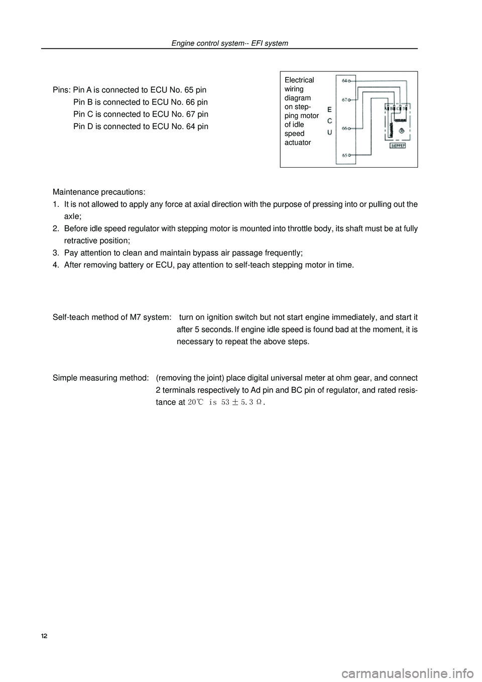
Resistance-temperature characteristics of temperature sensor 11 Temperature range( Resistance at A and CResistance at B
Page 23 of 419

Pins: Pin A is connected to ECU No. 65 pin
Pin B is connected to ECU No. 66 pin
Pin C is connected to ECU No. 67 pin
Pin D is connected to ECU No. 64 pin
Maintenance precautions:
1. It is not allowed to apply any force at axial direction with the purpose of pressing into or pulling out the
axle;
2. Before idle speed regulator with stepping motor is mounted into throttle body, its shaft must be at fully
retractive position;
3. Pay attention to clean and maintain bypass air passage frequently;
4. After removing battery or ECU, pay attention to self-teach stepping motor in time.
Self-teach method of M7 system: turn on ignition switch but not start engine immediately, and start it
after 5 seconds. If engine idle speed is found bad at the moment, it is
necessary to repeat the above steps.
Simple measuring method:(removing the joint) place digital universal meter at ohm gear, and connect
2 terminals respectively to Ad pin and BC pin of regulator, and rated resis-
tance at Engine control system·- EFI systemElectrical
wiring
diagram
on step-
ping motor
of idle
speed
actuator12
Page 24 of 419

Engine control system·- Throttle body assemblyThrottle body assemblyRemoving, installing and disassembling, assembling1. Discharge coolant (see Page 73).
2. Remove air cleaner hose assembly.
3. Remove engine plastic hood components [4G18-1000310].
4. Remove throttle pull cable assembly.
5. remove throttle body assembly [4G18-1008240].(a) Uncouple throttle position sensor joint and stepping motor joint.
(b) Disassemble ventilation hose.
(c) Remove 2 bolts and throttle control pull cable bracket.
(d) Remove 2 preheating water inlet and outlet hoses of throttle.
(e) Remove 2 bolts and 2 nuts, and remove throttle body from intake air manifold.6. Remove stepping motor of throttle body [4G18-3600070].Remove 3 screws and stepping motor.7. Install stepping motor of throttle body.Install stepping motor.8. Install throttle body assembly.(a) Install new seal gasket on intake air manifold.
(b) Install throttle body, 2 bolts and 2 nuts.
Torque: 9. Refill coolant.
10.Check there is leakage with coolant.
13