Page 73 of 419

Engine mechanism - Crankshaft rear oil seal assemblyReplacement1. Remove transmission assembly.
2. Remove clutch assembly and flywheel components.Fix crankshaft with special tool, remove clutch assembly at
first, and then remove flywheel components.3. Remove crankshaft rear oil seal.(a) Cut oil seal mouth with blade.
(b) Prize out oil seal with flathead screwdriver whose sharp
end is winded with tape.
Note: check crankshaft is damaged after removing oil
seal, and repair with abrasive paper (#400) if it is
damaged.4. Install crankshaft rear oil seal [4G18-1002130].(a) Coat a little MP grease on new oil seal lip.
Note: do not let oil seal lip contact with foreign
matters.
(b) Gently knock new oil seal in with special tool and hammer
until the seal surface is parallel and level with the end sur-
face edge of mounting hole.
Note: wipe off redundant grease on crankshaft.5. Install flywheel components and clutch assembly.(a) Fix crankshaft with special tool.
(b) Clean bolts and bolt holes.
(c) Coat bolts with adhesive.
Adhesive: thread locking adhesive 1234 (Kesaixin 1234)
(d) Install flywheel components.
As sequences shown in the diagram, tighten bolts at sev-
eral times.
Torque: (e) Install clutch assembly.6. Install transmission assembly.Special
tool
Cut
positionSpecial
tool62Crankshaft rear oil seal assembly
Page 74 of 419

Engine mechanism - Cylinder cover gasket componentsReplacement1. Take measures to prevent gasoline leaking.
2. Remove timing chain assembly.
3. Remove camshaft.As sequences shown in the diagram, evenly loosen at
several times, and remove 19 bearing cover bolts, and then
remove 9 bearing covers of intake camshaft and exhaust
camshaft.4. Remove cylinder head assembly.(a) Remove warm air water outlet pipe from cylinder head.
(b) As shown in the diagram, evenly loosen 10 cylinder head
bolts with 10mm dual hexagonal sleeves at several times,
and then remove 10 cylinder head bolts and plain washer.
Notes:Be careful not to let washer fall into cylinder head. Incorrect disassembling sequence will cause cylin-
der head warp or chap.5. Remove cylinder head gasket components
[4G18-1003160].
6. Install cylinder head gasket components.Put new cylinder head gasket on the cylinder body.
Notes:Pay attention to installation direction.Gently put down cylinder head to avoid damaging
cylinder head gasket.7. Install cylinder head assembly.Hint: Lock up cylinder head bolts as 2 steps.
(a) Coat a thin layer of engine oil at bolt thread and the bottom
of bolt head.
(b) As shown in the diagram, evenly tighten 10 cylinder head
bolts and plain washer with 10mm dual hexagonal sleeves
at several times.
Torque: 63Cylinder cover gasket components
Page 75 of 419
Engine mechanism - Cylinder cover gasket components(c) Tighten each cylinder head bolt in turn again.
Torque: m
(d) Install heating air water outlet pipe components.
Torque: 8. Install camshaft.(a) Coat engine oil on camshaft journal.
(b) Put 2 camshafts on cylinder head and with cylinder 1 cam-
shaft end toward the direction shown in the diagram.
(c) Check forward remarks and figures of all bearing cover, and
tighten the bolts as sequences shown in the diagram.
Torque:
Camshaft front bearing cover: Camshaft bearing cover: 9. Check idle speed and ignition timing.
10. Check compression pressure.
11. Check CO/HC.64
Page 76 of 419

Exhaust - Exhaust pipe assemblyExhaustExhaust pipe assemblyRemoving, installing and disassembling, assembling1. Remove oxygen sensor.(a) Uncouple oxygen sensor joint.
(b) Remove oxygen sensor.2. Remove exhaust pipe guard [64000051].
3. Remove front exhaust pipe together with three-way catalytic converter assembly
[64000042].
4. Remove middle exhaust pipe together with middle silencing device assembly [64000043].
5. Remove rear exhaust pipe together with rear silencing device assembly [64000044].
6. Install front exhaust pipe together with three-way catalytic converter assembly [64000042].(a) Measure free length of compression spring with vernier caliper.
Free length: 43mm
Hint: if the free length does dot reach the standard value, it is necessary to replace compres-
sion spring.
(b) Gently knock silencing device inlet seal ring to exhaust manifold with hammer and wooden block until
the surfaces are parallel and level with each other.
Notes:Gently knock gasket toward positive direction.Do not repeat using the gasket that has been removed.Do not push the gasket in by means of tightening
bolt connection.
(c) Install exhaust pipe.
Torque: 43 N.m7. Install oxygen sensor.Torque: 44 N.m9. Install rear exhaust pipe together with rear guard
assembly [64000044].(a) Measure free length of compression spring with vernier
caliper.
Free length: 40mm
Hint: if the free length does dot reach the standard value, it is necessary to replace com-
pression spring.
(b) Install tail pipe to front pipe using a new gasket.
Torque: 43 N.m10. Install front exhaust pipe guard [64000051].
11. Check there is gas leakage with exhaust system.wooden
blockGaskett8. Install middle exhaust pipe together with middle si-
lencing device assembly [64000043].Couple front intake pipe of middle exhaust pipe together with
middle silencing device assembly with outlet pipe of front ex-
haust pipe together with three-way catalytic converter using a
new gasket.Torque: 43 N.mTail pipe sideGasket65
Page 77 of 419

Cooling - Cooling syste2. Check engine coolant level in reservoir.Engine coolant level should be between “Low” and “Full” mark line.
Hint: if the level is too low, check there is leakage and refill coolant to “Full” mark line.3. Check engine coolant quality.(a) Remove radiator cap.
Warning: when the temperature of engine and radiator is high, do not remove radiator cap to
avoid being scalded, because coolant and steam will spurt under high pressure.
(b) Check there is too much rust deposit around radiator cap or at outlet and check there is flake; there
should not be oil in the coolant.
Hint: if coolant is too dirty, it is required to replace coolant.
(c) Install back radiator cap.Inspection1. Temperature regulatorHint: the figure on temperature regulator is the
opening temperature of valve.CoolingCooling systemOn-vehicle inspection1. Check there is leakage with cooling system.Warning: when the temperature of engine and radiator is
high, do not remove radiator cap to avoid be-
ing scalded, because coolant and steam will
spurt under high pressure.
(a) Refill coolant to radiator, and install radiator cap tester.
(b) Preheat engine.
(c) Pump tester to make pressure go up to 118KPa, and check
the pressure falls.
Hint: if the pressure falls, check there is leakage with
hose, radiator or water pump, and check heater,
cylinder body and cylinder head if no external leak-
age is found.66
Page 78 of 419

Cooling - Cooling systeTemperatureDegree of valve opening(a) Immerse temperature regulator into water and heat
gradually.
(b) Check opening temperature of valve.
Opening temperature of valve: 8084Hint: if opening temperature of valve is not within
specified range, it is required to replace tempera-
ture regulator.
(c) Check opening of valve.
Opening of valve:2. Radiator cap assemblyNotes:If radiator is dirty, wash it with clean water.Before using radiator cap tester, dampen relief valve
and pressure valve with coolant or water.
(a) Use radiator cap tester to slowly pump radiator cap
tester, and check the air is released by vacuum valve.
Pumping speed: 1 time /(3 seconds or more)
Note: pump radiator tester with constant speed.
Hints:Pumping speed: 1 time /(3 seconds or more)If air could not be released by vacuum valve,
please replace radiator cap.
(b) Pump tester and check opening pressure of relief valve.
Standard opening pressure: 74-108KPa
Min. opening pressure: 59KPa
Note: pumping speed means that the speed could be increased after the first time pumping
speed (to close vacuum valve).
Hints:Pumping speed: 1 time within 1 secondMax. reading of tester is opening pressure.If opening pressure is less than min. value, please replace radiator cap. Hint: if degree of valve opening is not within speci-
fied range, it is required to replace tempera-
ture regulator.
(a) When temperature regulator is at low temperature (below), check valve is tightly closed.
Hint: if the valve could not be closed, it is required to
replace temperature regulator.67
Page 79 of 419

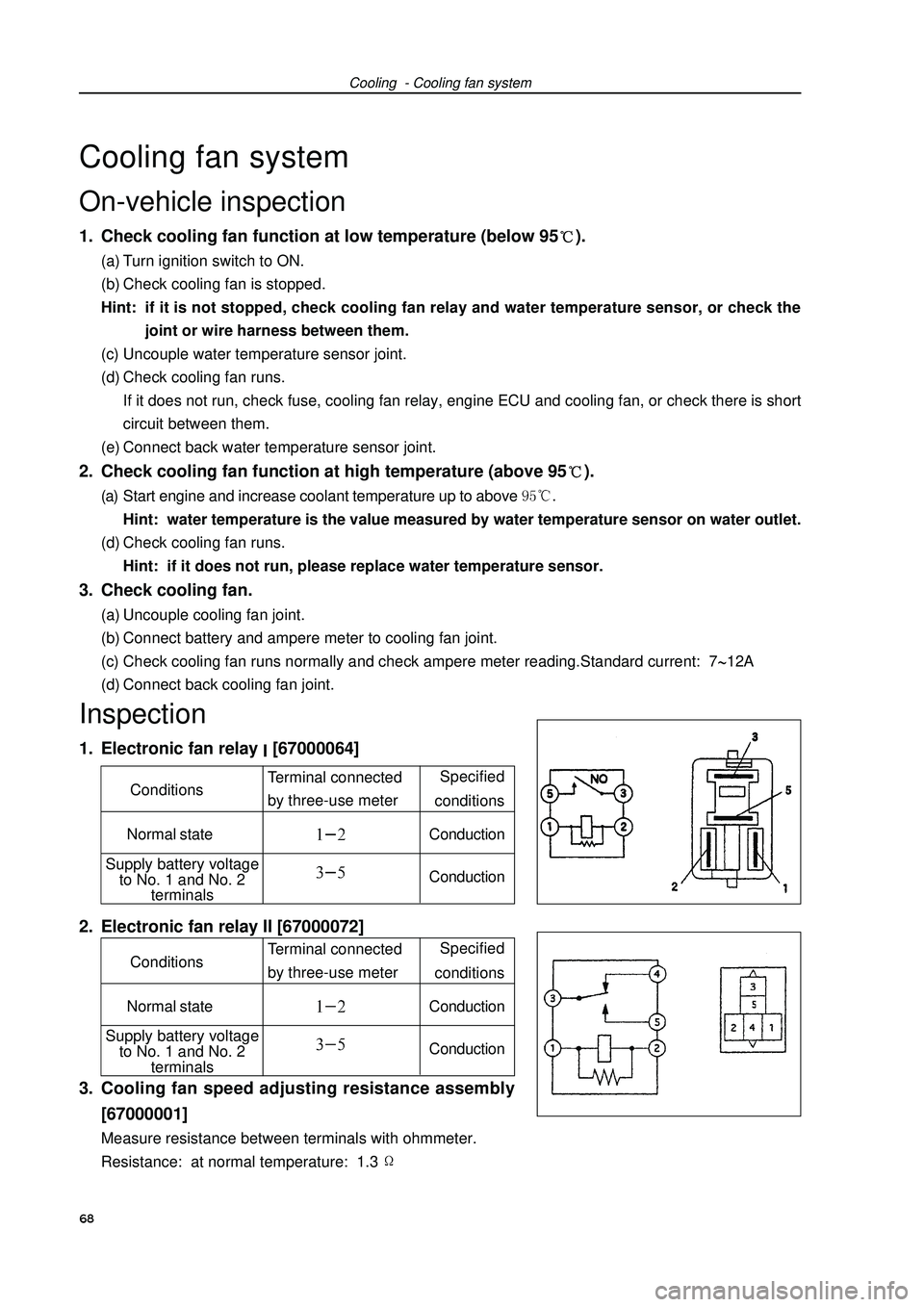
Cooling - Cooling fan systemCooling fan systemOn-vehicle inspection1. Check cooling fan function at low temperature (below 95).(a) Turn ignition switch to ON.
(b) Check cooling fan is stopped.
Hint: if it is not stopped, check cooling fan relay and water temperature sensor, or check the
joint or wire harness between them.
(c) Uncouple water temperature sensor joint.
(d) Check cooling fan runs.
If it does not run, check fuse, cooling fan relay, engine ECU and cooling fan, or check there is short
circuit between them.
(e) Connect back water temperature sensor joint.2. Check cooling fan function at high temperature (above 95).(a) Start engine and increase coolant temperature up to above Hint: water temperature is the value measured by water temperature sensor on water outlet.
(d) Check cooling fan runs.
Hint: if it does not run, please replace water temperature sensor.3. Check cooling fan.(a) Uncouple cooling fan joint.
(b) Connect battery and ampere meter to cooling fan joint.
(c) Check cooling fan runs normally and check ampere meter reading.Standard current: 712A
(d) Connect back cooling fan joint.Inspection1. Electronic fan relay [67000064]
2. Electronic fan relay II [67000072]
3. Cooling fan speed adjusting resistance assembly
[67000001]Measure resistance between terminals with ohmmeter.
Resistance: at normal temperature: 1.368 Specified
conditions
Normal stateConductionConductionTerminal connected
by three-use meter Conditions
Supply battery voltage
to No. 1 and No. 2
terminals
Specified
conditions
Normal stateConductionConductionTerminal connected
by three-use meter Conditions
Supply battery voltage
to No. 1 and No. 2
terminals
Page 80 of 419
Cooling - Water pump assemblyWater pump assemblyReplacement1. Remove engine right bottom shield.
2. Discharge engine coolant.
3. Remove drive belt.Slowly turn drive belt tensioner clockwise to loosen the belt;
then remove drive belt and put back drive belt tensioner slowly
to completely loosen the tensioner.4. Remove alternator assembly.(a) Remove rubber cover and nuts.
(b) Uncouple alternator joint.
(c) Remove 2 bolts and alternator.5. Remove water pump assembly.Remove 6 bolts, water pump and o-ring.69