2008 GEELY FC oil level
[x] Cancel search: oil levelPage 34 of 419

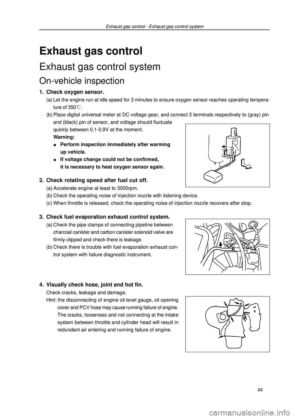
Exhaust gas controlExhaust gas control systemOn-vehicle inspection1. Check oxygen sensor.(a) Let the engine run at idle speed for 3 minutes to ensure oxygen sensor reaches operating tempera-
ture of 350(b) Place digital universal meter at DC voltage gear, and connect 2 terminals respectively to (gray) pin
and (black) pin of sensor, and voltage should fluctuate
quickly between 0.1-0.9V at the moment.
Warning:Perform inspection immediately after warming
up vehicle.If voltage change could not be confirmed,
it is necessary to heat oxygen sensor again.Exhaust gas control - Exhaust gas control system2. Check rotating speed after fuel cut off.(a) Accelerate engine at least to 3500rpm.
(b) Check the operating noise of injection nozzle with listening device.
(c) When throttle is released, check the operating noise of injection nozzle recovers after stop.3. Check fuel evaporation exhaust control system.(a) Check the pipe clamps of connecting pipeline between
charcoal canister and carbon canister solenoid valve are
firmly clipped and check there is leakage.
(b) Check there is trouble with fuel evaporation exhaust con-
trol system with failure diagnostic instrument.4. Visually check hose, joint and hot fin.Check cracks, leakage and damage.
Hint: the disconnecting of engine oil level gauge, oil opening
cover and PCV hose may cause running failure of engine.
The cracks, looseness and not connecting at the intake
system between throttle and cylinder head will result in
redundant air entering and running failure of engine.23
Page 50 of 419

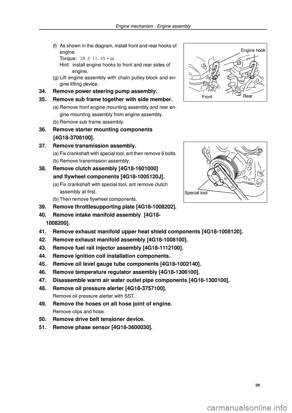
34. Remove power steering pump assembly.
35. Remove sub frame together with side member.(a) Remove front engine mounting assembly and rear en-
gine mounting assembly from engine assembly.
(b) Remove sub frame assembly.36. Remove starter mounting components
[4G18-3708100].
37. Remove transmission assembly.(a) Fix crankshaft with special tool, ant then remove 6 bolts.
(b) Remove transmission assembly.38. Remove clutch assembly [4G18-1601000]
and flywheel components [4G18-1005120J].(a) Fix crankshaft with special tool, ant remove clutch
assembly at first.
(b) Then remove flywheel components.39. Remove throttlesupporting plate [4G18-1008202].
40. Remove intake manifold assembly [4G18-
1008200].(f) As shown in the diagram, install front and rear hooks of
engine.
Torque: Hint: install engine hooks to front and rear sides of
engine.
(g) Lift engine assembly with chain pulley block and en-
gine lifting device.Engine mechanism - Engine assemblySpecial tool39 41. Remove exhaust manifold upper heat shield components [4G18-1008120].
42. Remove exhaust manifold assembly [4G18-1008100].
43. Remove fuel rail injector assembly [4G18-1112100].
44. Remove ignition coil installation components.
45. Remove oil level gauge tube components [4G18-1002140].
46. Remove temperature regulator assembly [4G18-1306100].
47. Disassemble warm air water outlet pipe components [4G18-1300100].
48. Remove oil pressure alerter [4G18-3757100].Remove oil pressure alerter with SST.49. Remove the hoses on all hose joint of engine.Remove clips and hose.50. Remove drive belt tensioner device.
51. Remove phase sensor [4G18-3600030].Engine hook
FrontRear
Page 52 of 419

Engine mechanism - Engine assembly64. Install temperature regulator assembly.(a) Check temperature regulator assembly o-ring.
(b) Install temperature regulator assembly as shown in the
diagram.
(c) Install engine water inlet pipe joint components.
Torque: 65. Install oil level gauge tube components.
66. Install ignition coil mounting components.Torque: m67. Install fuel rail injector assembly.(a) Install isolator on cylinder head.
(b) Install fuel rail injector assembly.
Torque: (c) Install fuel pipe retaining clip.68. Install exhaust manifold gasket and exhaust
manifold assembly.Torque: 69. Install exhaust manifold upper heat shield
components.Torque: 70. Install intake manifold assembly.Install new gasket and intake manifold assembly.
Torque: m71. Install throttle supporting plate.Torque: 72. Install flywheel components and clutch assembly.(a) Fix crankshaft with special tool.
(b) Clean bolts and bolt holes.
(c) Coat bolts with adhesive.
Adhesive: thread locking sealant 1234 (Kesaixin 1234).
(d) Install flywheel components.
As sequences shown in the diagram, tighten bolts at
several times.
Torque: 885Nm
(e) Install clutch assembly.Special
tool 41
Page 59 of 419

Engine mechanism - Timing chain assembly30. Install crankshaft front oil seal assembly.(a) Coat a little MP grease on oil seal lip.
(b) Gently knock new oil seal in with special tool and ham-
mer until the seal surface is parallel and level with the
edge of timing chain cover.
Note: do not let oil seal mouth contact with foreign
matters.31. Install timing chain hood components.(a) Eliminate all old seal materials from contact surface.
(b) As shown in the diagram, coat sealant on the edge
(diameter 3.5mm-4.5mm).
Sealant: silicon rubber flange sealant 1596 (Kesaixin
1596).
(c) Install timing chain hood with 12 bolts and nuts.
Torque: Notes:Eliminate all grease on contact surface.After coating sealant, finish installation of timing chain
hood within 3 minutes.After installing, do not refill engine oil within 2 minutes.32. Install chain tensioner components.(a) Check o-ring is clean, and buckle on the hook as shown
in the diagram.Special
tool 48 SealantSealant widthChain cover
groove
Cylinder
head groove Sealant
concentrationEntering
Hook
PinLifting
Page 72 of 419

Engine mechanism - Crankshaft front oil seal assembly5. Remove crankshaft front oil seal.(a) Cut oil seal lip with blade.
(b) Prize out oil seal with flat screwdriver whose sharp end is
winded with tape.
Note:check crankshaft is damaged after removing oil
seal, and repair with abrasive paper (#400) if it
is damaged.6. Install crankshaft front oil seal.(a) Coat a little MP grease on new oil seal lip.
Note: do not let oil seal lip contact with foreign
matters.
(b) Gently knock new oil seal in with special tool and hammer
until the seal surface is parallel and level with the end sur-
face edge of mounting hole.
Note: wipe off redundant grease on crankshaft.7. Install damping pulley.(a) Align the key groove on the pulley with the key on the
crankshaft, and slide pulley in.
(b) Install pulley bolts with special tool.
Torque: m8. Install right engine mounting assembly.Torque: 9. Check there is oil leakage.Cut
position
Prizing out
Special
tool61Special
tool
Page 73 of 419

Engine mechanism - Crankshaft rear oil seal assemblyReplacement1. Remove transmission assembly.
2. Remove clutch assembly and flywheel components.Fix crankshaft with special tool, remove clutch assembly at
first, and then remove flywheel components.3. Remove crankshaft rear oil seal.(a) Cut oil seal mouth with blade.
(b) Prize out oil seal with flathead screwdriver whose sharp
end is winded with tape.
Note: check crankshaft is damaged after removing oil
seal, and repair with abrasive paper (#400) if it is
damaged.4. Install crankshaft rear oil seal [4G18-1002130].(a) Coat a little MP grease on new oil seal lip.
Note: do not let oil seal lip contact with foreign
matters.
(b) Gently knock new oil seal in with special tool and hammer
until the seal surface is parallel and level with the end sur-
face edge of mounting hole.
Note: wipe off redundant grease on crankshaft.5. Install flywheel components and clutch assembly.(a) Fix crankshaft with special tool.
(b) Clean bolts and bolt holes.
(c) Coat bolts with adhesive.
Adhesive: thread locking adhesive 1234 (Kesaixin 1234)
(d) Install flywheel components.
As sequences shown in the diagram, tighten bolts at sev-
eral times.
Torque: (e) Install clutch assembly.6. Install transmission assembly.Special
tool
Cut
positionSpecial
tool62Crankshaft rear oil seal assembly
Page 77 of 419

Cooling - Cooling syste2. Check engine coolant level in reservoir.Engine coolant level should be between “Low” and “Full” mark line.
Hint: if the level is too low, check there is leakage and refill coolant to “Full” mark line.3. Check engine coolant quality.(a) Remove radiator cap.
Warning: when the temperature of engine and radiator is high, do not remove radiator cap to
avoid being scalded, because coolant and steam will spurt under high pressure.
(b) Check there is too much rust deposit around radiator cap or at outlet and check there is flake; there
should not be oil in the coolant.
Hint: if coolant is too dirty, it is required to replace coolant.
(c) Install back radiator cap.Inspection1. Temperature regulatorHint: the figure on temperature regulator is the
opening temperature of valve.CoolingCooling systemOn-vehicle inspection1. Check there is leakage with cooling system.Warning: when the temperature of engine and radiator is
high, do not remove radiator cap to avoid be-
ing scalded, because coolant and steam will
spurt under high pressure.
(a) Refill coolant to radiator, and install radiator cap tester.
(b) Preheat engine.
(c) Pump tester to make pressure go up to 118KPa, and check
the pressure falls.
Hint: if the pressure falls, check there is leakage with
hose, radiator or water pump, and check heater,
cylinder body and cylinder head if no external leak-
age is found.66
Page 85 of 419

LubricationLubricating systemOn-vehicle inspection1. Check oil level.During engine warming up and after it flames out for 5 minutes, check oil level, and the level should
be between two marks on oil dipstick at the moment.If oil level is too low, check there is leakage, and
refill oil up to upper mark on oil dipstick.
Note: oil level should not be above upper mark on oil
dipstick.2. Check oil quality.(a) Check there is deterioration, water penetration, color
change or thinning with oil.
(b) If oil quality becomes poor, please replace with new oil.
Hint: oil grades: API, SH, SJ, SG grade oil or ILSAC
multigrade oil. Recommended viscosity is
shown as below.
The temperature increases from left to right.3. Remove oil pressure alerter assembly.(a) Uncouple oil pressure alerter joint.
(b) Install oil pressure alerter with special tool.4. Install oil pressure gauge.Install oil pressure gauge.5. Warm up vehicle.
6. Check oil pressure.Oil pressure:7. Install oil pressure alerter.(a) Coat adhesive on 2nd or 3rd circle thread of oil pressure
alerter.
Adhesive: anaerobic pipe thread sealing adhesive
1545 (Kesaixin 1545).
(b) Install oil pressure alerter with special tool.
Torque: m
(c) Connect oil pressure alerter joint.8. Start engine and check there is leakage.Lubrication - lubricating systemRecommended viscosity (SAE)
Oil pressure alerter
Oil pressure gauge
Adhesive74Temperature range in forecasting next
oil replacement