Page 37 of 419
![GEELY FC 2008 Workshop Manual Engine mechanismEngine assemblyInspection1. Check coolant.
2. Check engine oil.
3. Check battery.
4. Check air filter assembly.
5. Check spark plug [4G18-3705113].
6. Check drive belt [4G18-1307107].H GEELY FC 2008 Workshop Manual Engine mechanismEngine assemblyInspection1. Check coolant.
2. Check engine oil.
3. Check battery.
4. Check air filter assembly.
5. Check spark plug [4G18-3705113].
6. Check drive belt [4G18-1307107].H](/manual-img/58/57161/w960_57161-36.png)
Engine mechanismEngine assemblyInspection1. Check coolant.
2. Check engine oil.
3. Check battery.
4. Check air filter assembly.
5. Check spark plug [4G18-3705113].
6. Check drive belt [4G18-1307107].Hint: do not check belt tension, because automatic tensioner is applied.7. Check ignition timing.(a) Warm up engine.
(b) Connect timing lamp to engine.
(c) Check ignition timing at idle speed.
Ignition timing: before top dead center Note: when checking ignition timing, place
transmission at neutral position.
Hint: After run the engine for 5 seconds with rotating
speed of 1000-1300rpm, check the engine could
recover to idle running.8. Check engine idle speed.(a) Warm up engine and run it at idle speed.
(b) Read engine rotating number in data flow with diagnostic instrument.
(c) Check idle speed.
Idle speed: about 750-850rpm
Notes:When checking idle speed, place cooling fan at OFF position.Turn off all auxiliary devices and air conditioner.Engine mechanism - Engine assemblyK-line 26
Page 89 of 419

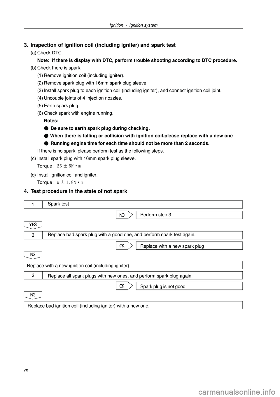
Ignition - Ignition system3. Inspection of ignition coil (including igniter) and spark test(a) Check DTC.
Note: if there is display with DTC, perform trouble shooting according to DTC procedure.
(b) Check there is spark.
(1) Remove ignition coil (including igniter).
(2) Remove spark plug with 16mm spark plug sleeve.
(3) Install spark plug to each ignition coil (including igniter), and connect ignition coil joint.
(4) Uncouple joints of 4 injection nozzles.
(5) Earth spark plug.
(6) Check spark with engine running.
Notes:Be sure to earth spark plug during checking. When there is falling or collision with ignition coil,please replace with a new oneRunning engine time for each time should not be more than 2 seconds.
If there is no spark, please perform test as the following steps.
(c) Install spark plug with 16mm spark plug sleeve.
Torque: (d) Install ignition coil and igniter.
Torque: 4. Test procedure in the state of not spark
78Perform step 3Spark testReplace with a new spark plugReplace bad spark plug with a good one, and perform spark test again.Spark plug is not goodReplace all spark plugs with new ones, and perform spark plug again.Replace with a new ignition coil (including igniter)Replace bad ignition coil (including igniter) with a new one.
Page 212 of 419

(e) If there is any foam or emulsification phenomenon, it is necessary to exhaust air in power steering
system.
(f) Keep the engine at idling speed, and measure the oil
level of oil storage tank.
(g) Engine extinguishes.
(h) After waiting for several minutes, measure the oil level
of oil storage tank again.
Maximal increased height of oil level: 5mm
If finding any problem, it is necessary to exhaust
the air in power steering system.
(i) Check the oil level.
4. Check steering oil pressure.
(a) Disassemble oil pressure supply pipe from power steering gear. (referring to page 205)
(b) Connect special tool liking that shown in figure.
Note: when checking, the valve of special tool should be opened.
(c) Exhaust the air in power steering system.
(d) Start the engine, and keep it at idling speed.
(e) Turn steering wheel from left bottom to right bottom for several times to make oil temperature
Power steering--Poser steering system
increase.
Oil temperature: 80°C
(f) Keep the engine at idling speed, and close the valve of
special tool, then observe the reading of special tool.
Minimal oil pressure: 6400kPa
Note:
�yThe closing time of oil pressure meter valve could not
Accessory
Power steering
gear
InOut
Accessory Oil pressure supply pipe
Power
steering
gearClose
Pump Oil tank
Special tool
¡Ü¡Ü
¡Ü¡Ü¡Ü5mm
Special tool
� 201 �
Page 245 of 419

Air conditioner--Compressor assembly
Compressor assembly
Change
1. Disassemble radiator cover.
2. Reclaim HFC-134a(R134a)
3. Disconnect refrigerant No.1 low pressure hose.
(a) Disassemble the bolt from compressor and electromag-
netic clutch assembly and disconnect refrigerant low pres-
sure hose.
(b) Disassemble O-shape loop from refrigerant low pressure
hose.
Note: after disassembling the pipeline, it is necessary
to cover the joint to prevent humidity or dust from
entering in system.
4. Disconnect refrigerant No.1 high pressure hose.
(a) Disassemble the bolt from compressor and electromag-
netic clutch assembly and disconnect refrigerant high pres-
sure hose.
(b) Disassemble O-shape loop from refrigerant high pressure
hose.
Note: after disassembling the pipeline, it is necessary
to cover the joint to prevent humidity or dust from
entering in system.
5. Disassemble right bottom defending cover of engine.
6. Disassemble driving belt.
7. Disassemble compressor and electromagnetic
clutch.
(a) Disconnect the joint.
(b) Disassemble three screws and electromagnetic clutch.
8. Check the Refrigerant oil.
� 234 �
When upgrading compressor assembly, it is necessary to reclaim the refrigerant in system at first.
Refrigerant oil quantity added by new compressor should be calculated by following formula.
Refrigerant oil standard quantity of new compressor:
(Inner Refrigerant oil quantity of new compressor:60 ± 10ml)-(Inner discharged Refrigerant oil quantity
of old compressor)=(Refrigerant oil quantity consumed by the system when changing)
Note:
�zWhen checking the Refrigerant oil quantity, please refer to the notes on page 206.
�zFor there is some Refrigerant oil in automobile pipeline, if some Refrigerant oil is not discharged
when assembling new compressor, this will incur the Refrigerant oil in system is too much to make
the system heat exchange become bad and air conditioning become invalid.