2008 GEELY FC wheel bolts
[x] Cancel search: wheel boltsPage 18 of 419

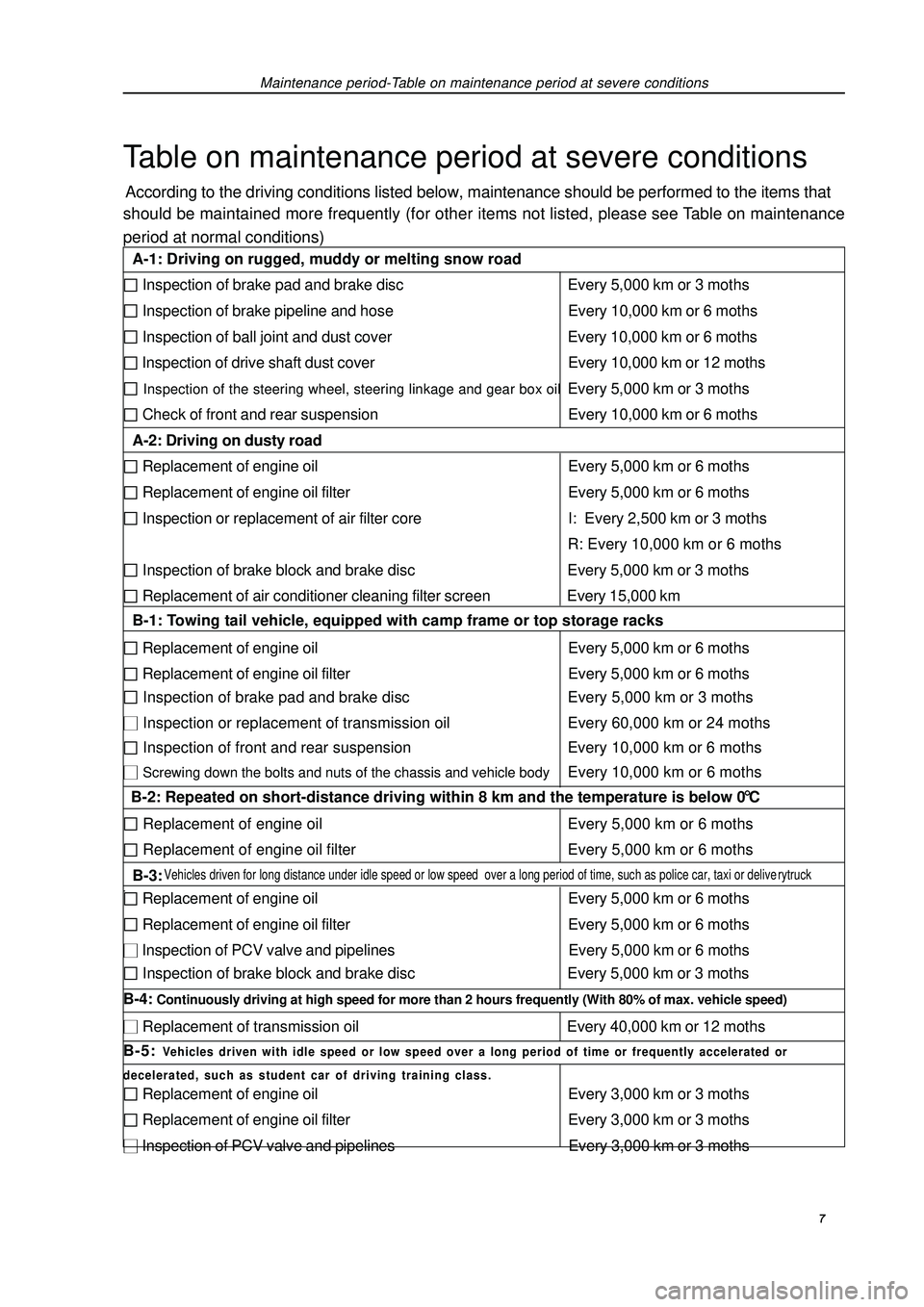
Maintenance period-Table on maintenance period at severe conditionsTable on maintenance period at severe conditionsAccording to the driving conditions listed below, maintenance should be performed to the items that
should be maintained more frequently (for other items not listed, please see Table on maintenance
period at normal conditions) 7 A-1: Driving on rugged, muddy or melting snow road Inspection of brake pad and brake disc Every 5,000 km or 3 moths Inspection of brake pipeline and hose Every 10,000 km or 6 moths Inspection of ball joint and dust cover Every 10,000 km or 6 moths Inspection of drive shaft dust cover Every 10,000 km or 12 moths Inspection of the steering wheel, steering linkage and gear box oilEvery 5,000 km or 3 moths Check of front and rear suspension Every 10,000 km or 6 moths
A-2: Driving on dusty road Replacement of engine oil Every 5,000 km or 6 moths Replacement of engine oil filter Every 5,000 km or 6 moths Inspection or replacement of air filter core I: Every 2,500 km or 3 moths
R: Every 10,000 km or 6 moths Inspection of brake block and brake disc Every 5,000 km or 3 moths Replacement of air conditioner cleaning filter screen Every 15,000 km
B-1: Towing tail vehicle, equipped with camp frame or top storage racks Replacement of engine oil Every 5,000 km or 6 moths Replacement of engine oil filter Every 5,000 km or 6 moths Inspection of brake pad and brake disc Every 5,000 km or 3 moths Inspection or replacement of transmission oil Every 60,000 km or 24 moths Inspection of front and rear suspension Every 10,000 km or 6 moths Screwing down the bolts and nuts of the chassis and vehicle bodyEvery 10,000 km or 6 moths
B-2: Repeated on short-distance driving within 8 km and the temperature is below 0 °C Replacement of engine oil Every 5,000 km or 6 moths Replacement of engine oil filter Every 5,000 km or 6 moths
B-3: Vehicles driven for long distance under idle speed or low speed over a long period of time, such as police car, taxi or deliverytruck. Replacement of engine oil Every 5,000 km or 6 moths Replacement of engine oil filter Every 5,000 km or 6 moths Inspection of PCV valve and pipelines Every 5,000 km or 6 moths Inspection of brake block and brake disc Every 5,000 km or 3 moths
B-4: Continuously driving at high speed for more than 2 hours frequently (With 80% of max. vehicle speed) Replacement of transmission oil Every 40,000 km or 12 moths
B-5: Vehicles driven with idle speed or low speed over a long period of time or frequently accelerated or
decelerated, such as student car of driving training class. Replacement of engine oil Every 3,000 km or 3 moths Replacement of engine oil filter Every 3,000 km or 3 moths Inspection of PCV valve and pipelines Every 3,000 km or 3 moths
Page 50 of 419

34. Remove power steering pump assembly.
35. Remove sub frame together with side member.(a) Remove front engine mounting assembly and rear en-
gine mounting assembly from engine assembly.
(b) Remove sub frame assembly.36. Remove starter mounting components
[4G18-3708100].
37. Remove transmission assembly.(a) Fix crankshaft with special tool, ant then remove 6 bolts.
(b) Remove transmission assembly.38. Remove clutch assembly [4G18-1601000]
and flywheel components [4G18-1005120J].(a) Fix crankshaft with special tool, ant remove clutch
assembly at first.
(b) Then remove flywheel components.39. Remove throttlesupporting plate [4G18-1008202].
40. Remove intake manifold assembly [4G18-
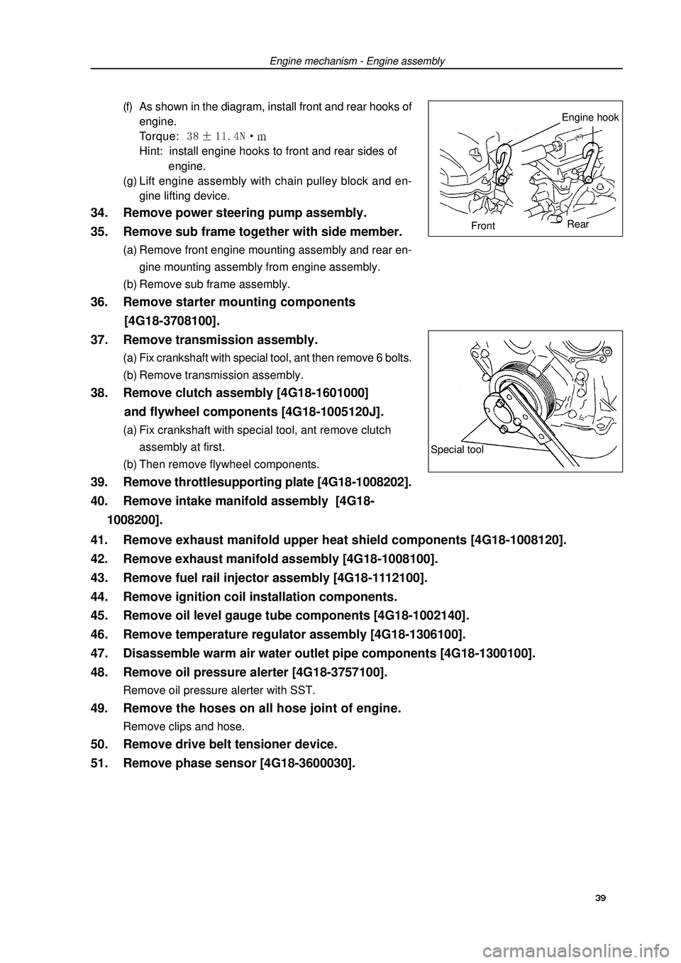
1008200].(f) As shown in the diagram, install front and rear hooks of
engine.
Torque: Hint: install engine hooks to front and rear sides of
engine.
(g) Lift engine assembly with chain pulley block and en-
gine lifting device.Engine mechanism - Engine assemblySpecial tool39 41. Remove exhaust manifold upper heat shield components [4G18-1008120].
42. Remove exhaust manifold assembly [4G18-1008100].
43. Remove fuel rail injector assembly [4G18-1112100].
44. Remove ignition coil installation components.
45. Remove oil level gauge tube components [4G18-1002140].
46. Remove temperature regulator assembly [4G18-1306100].
47. Disassemble warm air water outlet pipe components [4G18-1300100].
48. Remove oil pressure alerter [4G18-3757100].Remove oil pressure alerter with SST.49. Remove the hoses on all hose joint of engine.Remove clips and hose.50. Remove drive belt tensioner device.
51. Remove phase sensor [4G18-3600030].Engine hook
FrontRear
Page 52 of 419

Engine mechanism - Engine assembly64. Install temperature regulator assembly.(a) Check temperature regulator assembly o-ring.
(b) Install temperature regulator assembly as shown in the
diagram.
(c) Install engine water inlet pipe joint components.
Torque: 65. Install oil level gauge tube components.
66. Install ignition coil mounting components.Torque: m67. Install fuel rail injector assembly.(a) Install isolator on cylinder head.
(b) Install fuel rail injector assembly.
Torque: (c) Install fuel pipe retaining clip.68. Install exhaust manifold gasket and exhaust
manifold assembly.Torque: 69. Install exhaust manifold upper heat shield
components.Torque: 70. Install intake manifold assembly.Install new gasket and intake manifold assembly.
Torque: m71. Install throttle supporting plate.Torque: 72. Install flywheel components and clutch assembly.(a) Fix crankshaft with special tool.
(b) Clean bolts and bolt holes.
(c) Coat bolts with adhesive.
Adhesive: thread locking sealant 1234 (Kesaixin 1234).
(d) Install flywheel components.
As sequences shown in the diagram, tighten bolts at
several times.
Torque: 885Nm
(e) Install clutch assembly.Special
tool 41
Page 55 of 419

Engine mechanism - Engine assembly85. Install alternator mounting components.Torque: 12mm bolt head A: 14mm bolt head B: 86. Install drive belt.
87. Install engine wire harness and all hoses
not connected.(a) Check and connect all joints of engine wire harness.
(b) Check and connect all hoses.88. Install transmission control pull cable assembly
and valve control pull cable.
89. Install air filter assembly and its hose.
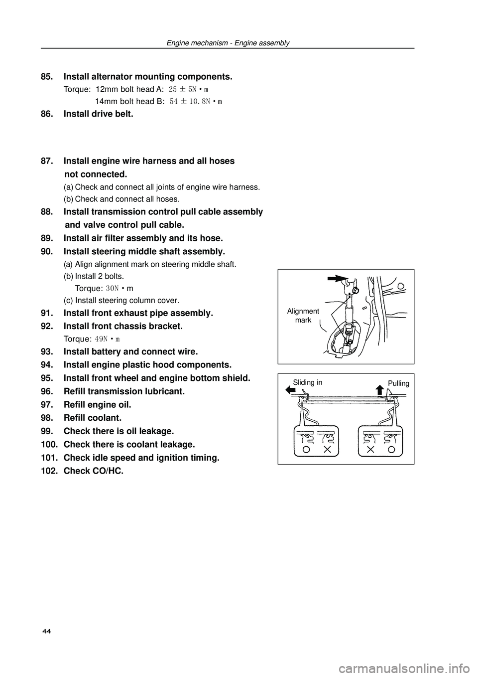
90. Install steering middle shaft assembly.(a) Align alignment mark on steering middle shaft.
(b) Install 2 bolts.
Torque: m
(c) Install steering column cover.91. Install front exhaust pipe assembly.
92. Install front chassis bracket.Torque: 93. Install battery and connect wire.
94. Install engine plastic hood components.
95. Install front wheel and engine bottom shield.
96. Refill transmission lubricant.
97. Refill engine oil.
98. Refill coolant.
99. Check there is oil leakage.
100. Check there is coolant leakage.
101. Check idle speed and ignition timing.
102. Check CO/HC.Alignment
mark
Sliding in
Pulling 44
Page 73 of 419

Engine mechanism - Crankshaft rear oil seal assemblyReplacement1. Remove transmission assembly.
2. Remove clutch assembly and flywheel components.Fix crankshaft with special tool, remove clutch assembly at
first, and then remove flywheel components.3. Remove crankshaft rear oil seal.(a) Cut oil seal mouth with blade.
(b) Prize out oil seal with flathead screwdriver whose sharp
end is winded with tape.
Note: check crankshaft is damaged after removing oil
seal, and repair with abrasive paper (#400) if it is
damaged.4. Install crankshaft rear oil seal [4G18-1002130].(a) Coat a little MP grease on new oil seal lip.
Note: do not let oil seal lip contact with foreign
matters.
(b) Gently knock new oil seal in with special tool and hammer
until the seal surface is parallel and level with the end sur-
face edge of mounting hole.
Note: wipe off redundant grease on crankshaft.5. Install flywheel components and clutch assembly.(a) Fix crankshaft with special tool.
(b) Clean bolts and bolt holes.
(c) Coat bolts with adhesive.
Adhesive: thread locking adhesive 1234 (Kesaixin 1234)
(d) Install flywheel components.
As sequences shown in the diagram, tighten bolts at sev-
eral times.
Torque: (e) Install clutch assembly.6. Install transmission assembly.Special
tool
Cut
positionSpecial
tool62Crankshaft rear oil seal assembly
Page 100 of 419

Front suspension - Front wheel alignment7. Adjustment of camberNote: after adjusting the camber, please check toe-in.
(a) Remove front wheels.
(b) Remove 2 nuts under absorber.
If it is necessary to repeat using bolts or nuts, please coat
oil to thread of nuts.
(c) Clean nut absorber and attachment face of steering knucle.
(d) Temporarily install 2 nuts.
(e) Push or pull lower end of absorber in the direction that cam-
ber requires adjustment to adjust the camber.
(f) Tighten nut.
Torque: 15310 N.m
(g) Install front wheels.
Torque: 10310 N.m
(h) Check camber.89
Page 101 of 419

Front suspension - Front shock absorber and helical spring 90Front absorber and helical springOverhaulHint: the following overhaul procedures only aim at left side (FL), and the overhaul procedures
of another side (RL) are the same as FL.1. Remove front wheels.
2. Separate front left stabilizer link assembly
[64000097].Remove nuts, and disassemble stabilizer link from absorber.
Hint: if ball joint rotates with nuts, please fix bolts with
hexagonal wrench (6mm).3. Remove front absorber and helical spring.(a) Remove bolts, and disassemble brake hose and ABS speed
sensor wire harness bracket.
(b) Remove 2 nuts and bolts under absorber.
(c) Remove 3 nuts above absorber.
(d) Remove absorber and helical spring.
Page 104 of 419

Front suspension - Front shock absorber and helical springHandling1. Handle front left absorber assembly.(a) Completely pull out absorber piston rod.
(b) As shown in the diagram, drill a small hole on cylinder body
between two lines with electric drill to make inside gas flow
out
Notes:Iron chip may fly out during drilling, please be care-
ful in operating.The gas is colorless, odorless and nontoxic.93(c) Install 2 nuts to lower end of absorber.
Torque: 15310 N.m
Hint: coat oil on thread of nuts.
(d) Install brake hose and ABS speed sensor wire harness
bracket with bolts.
Torque: 19N.m9. Install front left stabilizer link assembly [64000097].Install stabilizer link with nuts.
Torque: 745 N.m
Hint: if ball joint rotates with nuts, please fix bolts with
hexagonal wrench (6mm).10. Install front wheels.Torque: 10310 N.m11. Check and adjust front wheel alignment
(see Page 87).