2008 GEELY FC parking brake
[x] Cancel search: parking brakePage 8 of 419

Brake
Brake system......................................................
132
Notes..............................................................
132
Remove malfunction...........................................
133
Malfunction phenomenon table.....................
133
Brake liquid.........................................................
135
Discharge the air in brake system.................
135
Brake pedal assembly........................................
136
Adjustment.....................................................
136
Change..........................................................
137
Vacuum booster assembly.................................
138
Inspection on automobile...............................
138
Change..........................................................
138
Front brake assembly.........................................
141
Overhaul........................................................
141
Rear brake assembly.........................................
144
Overhaul........................................................
144Hydraulic pressure control unit (equipping with ABS)...148
Inspection on automobile...............................
148
Change..........................................................
148
Speed sensor of front wheel..............................
151
Change..........................................................
151
Speed sensor of rear wheels...........................
152
Change..........................................................
152
Parking brake
Parking brake system.........................................
154
Malfunction phenomenon table.....................
154
Adjustment.....................................................
154
Parking brake handle assembly.........................
155
Change..........................................................
155
Parking front bake pull cable assembly............
156
Change..........................................................
156
Parking rear brake pull cable assembly...........
158
Change..........................................................
158
Parking brake assembly....................................
161
Overhaul........................................................
161Transmission
Disassemble assembly...................................
165
Assemble the assembly....................................
191
Steering column
Steering system..................................................
192
Note...............................................................
192
Malfunction phenomenon table.....................
192
Inspection on automobile...............................
193
Steering column system.....................................
194
Overhaul........................................................
194
Power steering
Power steering system......................................
198
Note...............................................................
198
Malfunction phenomenon table....................
199
Inspection on automobile.............................
200
Power steering oil pump assembly..................
203
Overhaul........................................................
203
Power steering gear assembly.........................
205
Overhaul........................................................
205
Air conditioner
Air conditioning system......................................
213
Note...............................................................
213
Inspection on automobile...............................
213
Inspection......................................................
214
Refrigerant..........................................................
215
Inspection on automobile...............................
215
Change..........................................................
221
Refrigerant pipeline............................................
222
Parts...............................................................
222Control assembly, air conditioner control panel (AUTO A/C)...223
Overhaul........................................................
223
Fan assembly...................................................
224
Overhaul........................................................
224
Air conditioner central heating core assembly..
227
Overhaul........................................................
227
Compressor assembly.....................................
234
Page 16 of 419

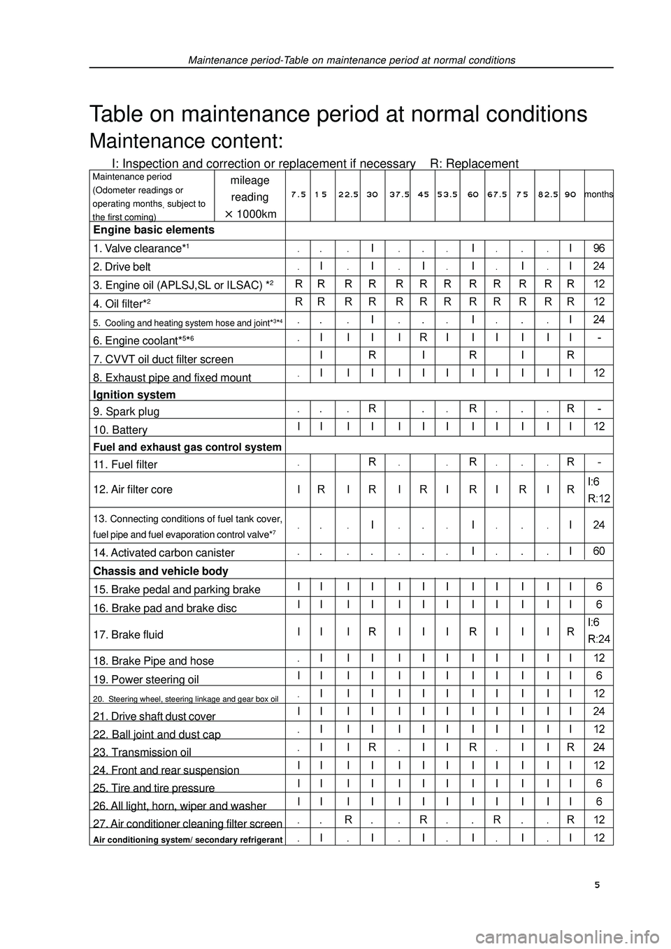
Maintenance period-Table on maintenance period at normal conditionsTable on maintenance period at normal conditionsMaintenance content:I: Inspection and correction or replacement if necessary R: Replacementmileage
reading1000kmMaintenance period
(Odometer readings or
operating monthssubject to
the first coming)Engine basic elements
1. Valve clearance*12. Drive belt
3. Engine oil (APLSJ,SL or ILSAC) *24. Oil filter*25. Cooling and heating system hose and joint*3*46. Engine coolant*5*67. CVVT oil duct filter screen
8. Exhaust pipe and fixed mount
Ignition system
9. Spark plug
10. BatteryFuel and exhaust gas control system11. Fuel filter
12. Air filter core13. Connecting conditions of fuel tank cover,
fuel pipe and fuel evaporation control valve*714. Activated carbon canister
Chassis and vehicle body
15. Brake pedal and parking brake
16. Brake pad and brake disc
17. Brake fluid
18. Brake Pipe and hose
19. Power steering oil20. Steering wheel, steering linkage and gear box oil21. Drive shaft dust cover
22. Ball joint and dust cap
23. Transmission oil
24. Front and rear suspension
25. Tire and tire pressure
26. All light, horn, wiper and washer
27. Air conditioner cleaning filter screenAir conditioning system/ secondary refrigerant7 . 5 1 5 22.5 3037.5 4553.5 60 67.5 7 582.5 90months 5
Page 33 of 419

Fuel - Fuel tank assemblyBe careful of the contaminant that looked like dirt, because
fast-joint depends on o-ring to seal fuel pipe and joint.Do not perform this operation with tools.Do not bend or distort nylon hose.Cover the joint with plastic bag after removing the fuel hose.When the joint is stuck with fuel pipe, clip the hose with
fingers and rotate carefully to release the hose, and then
remove it.14. Remove fuel tank assembly(a) Remove parking brake pull cable retaining clip.
(b) Place jack under fuel tank. Remove fuel tank band harness and fuel
tank assembly.15. Remove fuel tank main fuel hose and oil return pipe
assembly
16. Remove No. 2 fuel evaporation hose assembly
17. Remove No. 1 fuel tank gasket
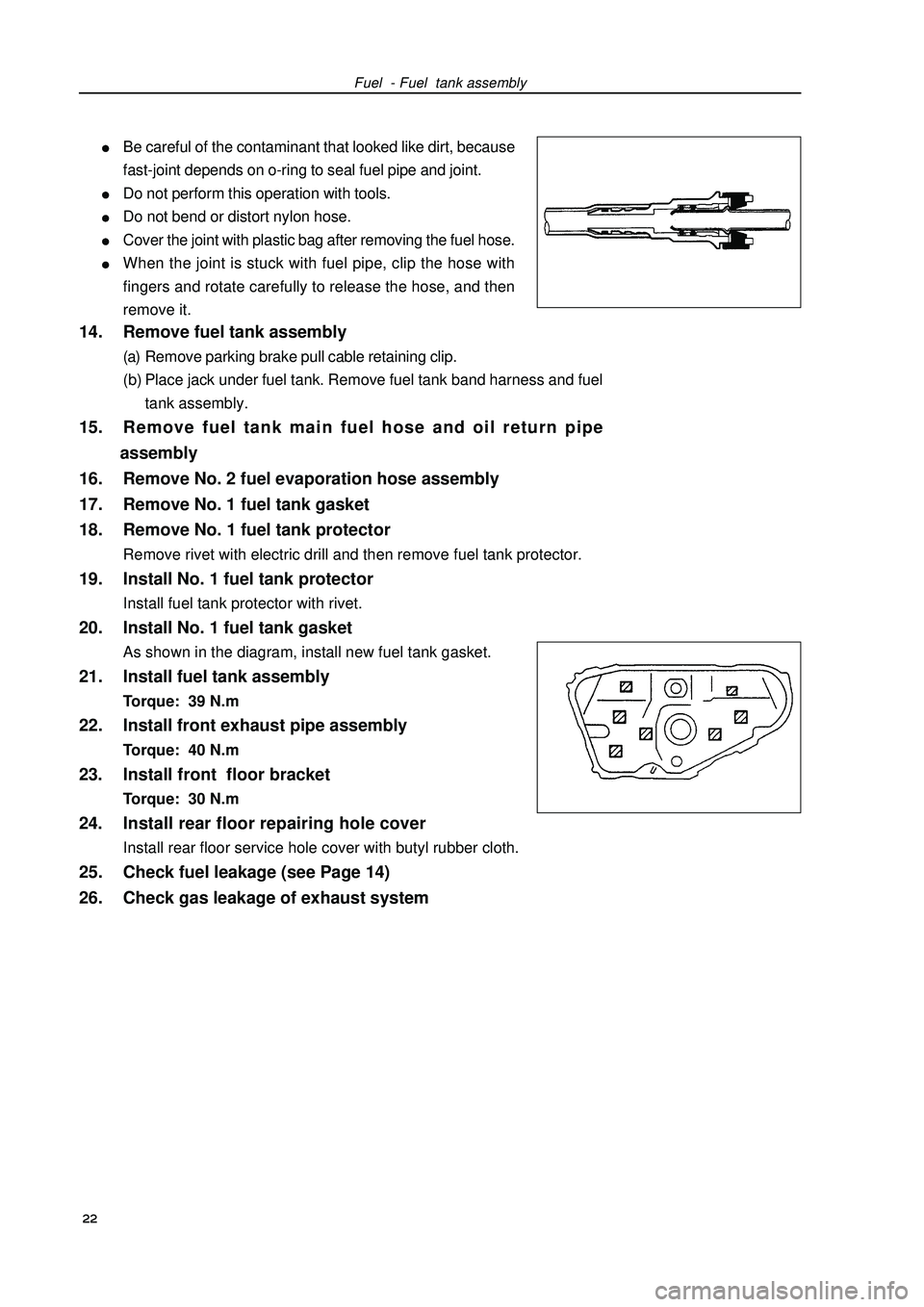
18. Remove No. 1 fuel tank protectorRemove rivet with electric drill and then remove fuel tank protector.19. Install No. 1 fuel tank protectorInstall fuel tank protector with rivet.20. Install No. 1 fuel tank gasketAs shown in the diagram, install new fuel tank gasket.21. Install fuel tank assemblyTorque: 39 N.m22. Install front exhaust pipe assemblyTorque: 40 N.m23. Install front floor bracketTorque: 30 N.m24. Install rear floor repairing hole coverInstall rear floor service hole cover with butyl rubber cloth.25. Check fuel leakage (see Page 14)
26. Check gas leakage of exhaust system
22
Page 119 of 419

14. Temporarily lock up rear left strut assembly.(a) Install rear left strut and gasket, and temporarily lock
up nuts.
(b) Perform to another side in the same way.15. Install rear stabilizer bar assembly (see Page 105).
16. Install rear left/right brake assembly [64000137/64000139] (see Page 144).
17. Install rear wheel speed sensor wire harness.Install wire harness and parking brake cable with 2 bolts and retaining clips.
Torque: (A) 5.4 N.m
(B) 5.0 N.mRear suspension - Rear shaft assembly108 18. Install rear left brake caliper assembly
(see Page 144).
19. Install rear right brake caliper assembly
(see Page 144).
20. Align suspension.(a) Lay down vehicle from the lift after installing rear wheels.
Torque: (b) Align suspension components by means of lifting ve-
hicle with a jack several times.21. Completely lock up rear shaft assembly
[64000120].(a) Completely tighten bolts and pull on open pin.
Torque: m
(b) Perform to another side in the same way.22. Completely lock up rear left strut assembly.(a) Completely tighten bolts.
Torque: m
(b) Perform to another side in the same way.23. Check rear wheel alignment (see Page 101).
24. Check ABS sensor signal.
Page 144 of 419

Brake--Remove malfunctionRemove malfunctionMalfunction phenomenon tableUse following table to help you find the reason of malfunction, the number in table indicates the preferred
sequence of possible reasons of malfunction. Please check every part by sequence, if necessary, change
this part.Malfunction phenomenon Possible malfunction part Reference page
1. Brake system (leaking oil). -
The height of brake pedal is too 2. Brake system (entering air). 135
low or brake pedal is loose. 3. Piston oil seal (abraded or damaged). 141, 144
4. Brake main pump (invalid) 138
5. Vacuum booster lever (adjusted badly) 138
1. Brake pedal free travel (too small). 136
2. Parking brake handle travel (adjusted badly). 154
3. Parking brake pull cable (lag). 156, 158
4. Brake block (damaged or distorted). 141, 144
Brake lag 5. Piston (locked). 141, 144
6. Piston (freezed).141, 144
7. Tensility or return spring (invalid). 161
8. Vacuum booster lever (adjusted badly). 138
9. Vacuum boosting system (vacuum leakage). 138
10. Brake main pump (invalid). 138
1. Piston (locked). 141, 144
2. Brake block (oil dirt).141, 144
Brake offset 3. Piston (freezed).141, 144
4. Brake disk (scratched). 141, 144
5. Brake block (abraded or distorted).141, 144
1. Brake system (leaking oil).
2. Brake system (entering air). 135
3. Brake block (abraded). 141, 144
4. Brake block (damaged or distorted). 141, 144Brake pedal is too hard to make power lack.5. Brake block (oil dirt).141, 144
6. Brake block (sclerosesed). 141, 144
7. Brake disk (scratched). 141, 144
8. Vacuum booster lever (adjusted badly). 138
9. Vacuum boosting system (vacuum leakage). 138133
Page 147 of 419

Brake--Remove malfunction2. Check the free travel of pedal.(a) Extinguish the engine, and step brake pedal repeatedly until
there is no vacuum in vacuum booster.
(b) Press down pedal with hand until feeling the resistance,
then measure the distance of this section, liking that shown
in figure.
Free travel of pedal: 1-6mm.
If it is wrong, check the clearance of brake light switch.
Clearance of brake light switch: 0.5-2.4mm
If the clearance accords with the regulation, remove the
malfunction in brake system.3. Check the distance from pedal to floor.Release parking brake drag lever
When engine is running, step down brake pedal, then mea-
sure the distance from pedal to floor, liking that shown in figure,
Force 490 N on pedal, its distance from floor should be:
over 60mm.
If it is wrong, remove the malfunction in brake system.Brake pedal assemblyAdjustment1. Check and adjust the height of brake pedal.(a) Check the height of brake pedal.
Pedal distance from floor: 136.0-146.0mm
(b) Adjust the height of brake pedal.
(1) Disassemble lower trim board of panel.
(2) Disassemble switch joint of brake light.
(3) Loosen locking nut of brake switch, and disassemble
the switch of brake light.
(4) Loosen U-shaped clasp fixing nut of pedal lever.
(5) Turn pedal lever to adjust the height of pedal.
(6) Lock the fixing nut of lever.
Torque: 26
± ±± ±
±2 N⋅ ⋅⋅ ⋅
⋅m
(7) Assemble the switch of brake switch.
(8) Connect the switch joint of brake light.
(9) Press down the brake pedal for 5-15mm, and turn the switch of brake light to illuminate brake light,
then lock the nut.
(10) After assembling, press down the brake pedal for 5-15mm again, and confirm brake light has
illuminated.Pedal distance
from floorFree travel of
pedal Height of pedal Push rodBrake light switch136
Page 149 of 419

Brake--Vacuum booster assemblyVacuum booster assemblyInspection on automobile1. Check the vacuum booster(a) Check the gas sealed performance.
(1) Start the engine, and extinguish after one or two minutes,
then step and release brake pedal slowly several times.
Hint: if the first step is lowest, second and third step
rise gradually, and this shows the gas sealed per-
formance of booster is normal.
(2) Step down brake pedal when engine is running, then
extinguish the engine.
Hint: if the distance from pedal to floor does not
change in 30 seconds, this shows gas seal perfor-
mance of booster is normal.
(b) Working inspection.
(1) When engine is at parking state, step brake pedal sev-
eral times to check brake pedal.
The height from floor should not change.
(2) Step down brake pedal, then start the engine.
Hint: if pedal drops a little, this shows working is
normal.2. Check vacuum check valve(a) Check vacuum check valve.
(1) Remove pipe clamp, and disassemble vacuum pipe.
(2) Disassemble vacuum check valve.
(3) Blow air to check: in the direction from booster to engine,
the check valve should ventilate, but its opposite direc-
tion should not ventilate.
(4) If finding any malfunction, change vacuum check valve.Change1. Discharge brake liquidNote: do not spill the brake liquid on paint surface of automobile body, if having, wash it cleanly.2. Disassemble air filter assembly [64000033]
3. Disassemble carbon canister assembly [4G18-1129020]
4. Disassemble brake main pump subassemblyGood
Bad
FirstSecondThird
Con-
ductionNot con-
duction138
Page 165 of 419

Parking brakeParking brake systemMalfunction phenomenon tableUse following table to find the reason of malfunction, the number in table indicates the preferred se-
quence of possible reason. Please check each part by sequence, if necessary, change this part.Parking brake--Parking brake systemAdjustment1. Disassemble rear wheels
2. Adjust the clearance of parking brake shoe
3. Assemble rear wheelsTorque: 103
± ±± ±
± 10 N
⋅ ⋅⋅ ⋅
⋅m4. Check the travel of parking brake handle.Pull up the parking brake handle and calculate the sound num-
ber of handle.
When parking brake handle locates 196N: 6-9 sounds.5. Adjust the travel of parking brake handle(a) Disassemble upper trim board of central box.
(b) Disassemble central box.
(c) Release locking screw cap, then rotate adjusting screw cap
until handle travel accords with the specification.
(d) Tighten locking screw cap.
Torque: 5.0 N
⋅ ⋅⋅ ⋅
⋅m
(e) Assemble central box.
(f) Assemble trim board on central box.Malfunction phenomenon Possible malfunction part Reference page
1. Travel of parking brake handle (adjusted badly). 154
2. Pull cable of parking brake (attached).156, 158
Brake lag 3. Clearance of parking brake shoe (adjusted badly). 161
4. Friction plate of parking brake shoe (damaged or distorted). 161
5. Tension or return spring (damaged). 161Lock the screw cap
Adjust the
screw cap154