2008 GEELY FC fuel filter
[x] Cancel search: fuel filterPage 3 of 419

Preface
Geely “FC” is an automobile with high performance/price ratio and it meets the requirement
of national safety, energy saving, emission regulations and personal use. This automobile is
a completely new and excellent model produced by Zhejiang Geely Automobile Co., Ltd with
development in self-reliance of Geely group and with self-dominated intellectual property
right. It characterizes elegant appearance,
energy conservation and environmental protection,
safety and comfort. “FC” is a product opening a completely new viewpoint of automobile
selection, because it is developed on the basis of creative design thinking that breaks through
all established customs and it features perfectly balanced performance of power, space,
safety, manipulation and comfort. “FC” is a competitive product for Geely developing brand
and exploring mid-level automobile market, which takes over the company philosophy “make
good cars that common people can afford, and let Geely cars go to the whole world” of Geely
automobile. “FC” is combination of creativity and intelligence of quite a large number of
automobile experts, who have been developing and searching with great concentration for
more than 30 months, and it fully embodies persistent Geely style of fashion appearance
and high performance/price ratio.
“FC” is equipped with engine JL4G18 completely developed and produced by Geely group.
Engine JL4G18 applies the following advanced technology such as VVT, full aluminum cylin-
der body, plastic intake manifold, completely new VVT inside seal method, completely new
OCV valve filtering method etc. with M7.9.7 electric injection system of BOSCH, and its
index on power efficiency, economical efficiency, and safety efficiency etc. reaches leading
level of national model with the same type. This engine features strong power, low fuel
consumption, low noise and high power per liter etc.
We start to compile “FC” Automobile Maintenance Manual, which is divided into 27 sec-
tions with detailed description of overall structure and maintenance of engine 4G18.VVT;
inspection and repair of engine BOSCH M7.9.7 electric control fuel injection system; struc-
ture and maintenance of chassis; structure and maintenance of FC electrical equipment;
structure and maintenance of ABS anti-lock brake system; structure and maintenance of
SRS air bag; structure and maintenance of auto air conditioning system; structure and main-
tenance of vehicle body etc. Information is detailed and accurate, contents are in systematic
coherence and description is concise and comprehensive.
This manual is compiled from structure, which prompts “FC” service personnel to master
Page 16 of 419

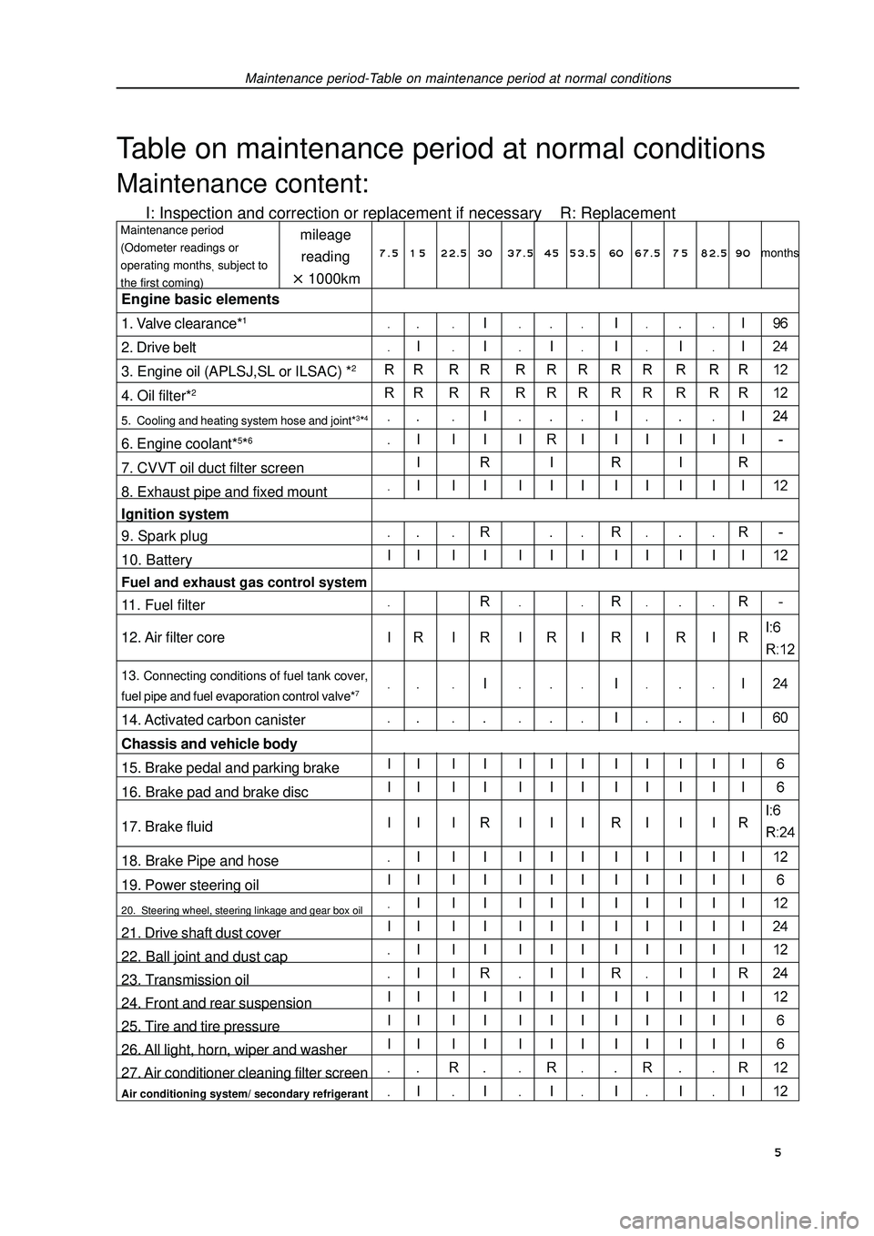
Maintenance period-Table on maintenance period at normal conditionsTable on maintenance period at normal conditionsMaintenance content:I: Inspection and correction or replacement if necessary R: Replacementmileage
reading1000kmMaintenance period
(Odometer readings or
operating monthssubject to
the first coming)Engine basic elements
1. Valve clearance*12. Drive belt
3. Engine oil (APLSJ,SL or ILSAC) *24. Oil filter*25. Cooling and heating system hose and joint*3*46. Engine coolant*5*67. CVVT oil duct filter screen
8. Exhaust pipe and fixed mount
Ignition system
9. Spark plug
10. BatteryFuel and exhaust gas control system11. Fuel filter
12. Air filter core13. Connecting conditions of fuel tank cover,
fuel pipe and fuel evaporation control valve*714. Activated carbon canister
Chassis and vehicle body
15. Brake pedal and parking brake
16. Brake pad and brake disc
17. Brake fluid
18. Brake Pipe and hose
19. Power steering oil20. Steering wheel, steering linkage and gear box oil21. Drive shaft dust cover
22. Ball joint and dust cap
23. Transmission oil
24. Front and rear suspension
25. Tire and tire pressure
26. All light, horn, wiper and washer
27. Air conditioner cleaning filter screenAir conditioning system/ secondary refrigerant7 . 5 1 5 22.5 3037.5 4553.5 60 67.5 7 582.5 90months 5
Page 31 of 419

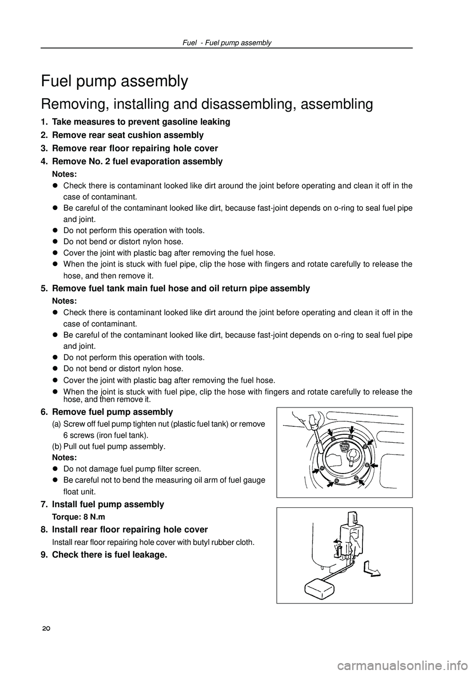
Fuel - Fuel pump assemblyFuel pump assemblyRemoving, installing and disassembling, assembling1. Take measures to prevent gasoline leaking
2. Remove rear seat cushion assembly
3. Remove rear floor repairing hole cover
4. Remove No. 2 fuel evaporation assemblyNotes:
�zCheck there is contaminant looked like dirt around the joint before operating and clean it off in the
case of contaminant.
�zBe careful of the contaminant looked like dirt, because fast-joint depends on o-ring to seal fuel pipe
and joint.
�zDo not perform this operation with tools.
�zDo not bend or distort nylon hose.
�zCover the joint with plastic bag after removing the fuel hose.
�zWhen the joint is stuck with fuel pipe, clip the hose with fingers and rotate carefully to release the
hose, and then remove it.5. Remove fuel tank main fuel hose and oil return pipe assemblyNotes:
�zCheck there is contaminant looked like dirt around the joint before operating and clean it off in the
case of contaminant.
�zBe careful of the contaminant looked like dirt, because fast-joint depends on o-ring to seal fuel pipe
and joint.
�zDo not perform this operation with tools.
�zDo not bend or distort nylon hose.
�zCover the joint with plastic bag after removing the fuel hose.
�zWhen the joint is stuck with fuel pipe, clip the hose with fingers and rotate carefully to release the
hose, and then remove it.6. Remove fuel pump assembly(a) Screw off fuel pump tighten nut (plastic fuel tank) or remove
6 screws (iron fuel tank).
(b) Pull out fuel pump assembly.
Notes:
�zDo not damage fuel pump filter screen.
�zBe careful not to bend the measuring oil arm of fuel gauge
float unit.7. Install fuel pump assemblyTorque: 8 N.m8. Install rear floor repairing hole coverInstall rear floor repairing hole cover with butyl rubber cloth.9. Check there is fuel leakage. 20
Page 39 of 419

Engine mechanism - Engine assemblyCO HC Trouble occurrence Possible causes 28 Normal HighUnstable idle speed
Low HighUnstable idle speed
(HC readings not stable)
High HighUnstable idle speed
(black smoke emission)1. Ignition system malfunctionIgnition timing incorrect Spark plug too dirty, short circuit or clearance
incorrect
2. Valve clearance incorrect
3. Air inlet and exhaust valve leaky
4. Cylinder leaky
1. Vacuum leak:PCV hoseIntake manifoldThrottle bodyIdle speed stepping motorVacuum booster and pipelines
2. Fire caused by too thin mixing ratio
1. Air filter core blocked
2. PCV valve blocked
3. EFI system malfunctionFuel pressure regulator malfunctionWater temperature sensor malfunctionIntake pressure sensor malfunctionECU malfunctionInjection nozzle malfunctionThrottle position sensor malfunction
Page 47 of 419

Engine mechanism - Engine assemblyEngine assemblyReplacement1. Take measures to prevent gasoline leaking.
2. Remove engine right bottom shield.
3. Remove engine left bottom shield.
4. Discharge coolant.
5. Remove front wheels.
6. Remove engine plastic hood components.
7. Remove battery.
8. Remove air filter assembly.
9. Remove air filter hose.
10. Remove battery tray.
11. Disassemble fuel hose assembly.
12. Remove throttle cable assembly.
13. Disassemble radiator hose inlet end.
14. Disassemble radiator hose outlet end.
15. Disassemble cold air pipe inlet hose.
16. Disassemble cold air pipe outlet hose.
17. Remove transmission control pull cable assembly.
18. Disassemble warm air water inlet hose [4G18-1300102].
19. Disassemble warm air water outlet hose [4G18-1300108].
20. Disassemble the hoses of all joints to connect vehicle body end.
21. Uncouple engine wire harness.(a) Remove glove compartment door.
(b) Remove engine wire harness from engine ECU and junction block.
(c) Pull out engine wire harness.
(b) Remove engine wire harness from junction block of engine room.
(e) Remove vehicle body earth wire. 36