2008 GEELY FC battery
[x] Cancel search: batteryPage 16 of 419
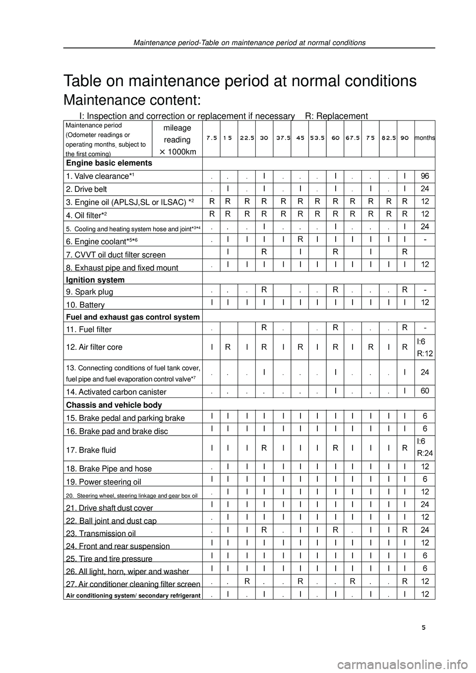
Maintenance period-Table on maintenance period at normal conditionsTable on maintenance period at normal conditionsMaintenance content:I: Inspection and correction or replacement if necessary R: Replacementmileage
reading1000kmMaintenance period
(Odometer readings or
operating monthssubject to
the first coming)Engine basic elements
1. Valve clearance*12. Drive belt
3. Engine oil (APLSJ,SL or ILSAC) *24. Oil filter*25. Cooling and heating system hose and joint*3*46. Engine coolant*5*67. CVVT oil duct filter screen
8. Exhaust pipe and fixed mount
Ignition system
9. Spark plug
10. BatteryFuel and exhaust gas control system11. Fuel filter
12. Air filter core13. Connecting conditions of fuel tank cover,
fuel pipe and fuel evaporation control valve*714. Activated carbon canister
Chassis and vehicle body
15. Brake pedal and parking brake
16. Brake pad and brake disc
17. Brake fluid
18. Brake Pipe and hose
19. Power steering oil20. Steering wheel, steering linkage and gear box oil21. Drive shaft dust cover
22. Ball joint and dust cap
23. Transmission oil
24. Front and rear suspension
25. Tire and tire pressure
26. All light, horn, wiper and washer
27. Air conditioner cleaning filter screenAir conditioning system/ secondary refrigerant7 . 5 1 5 22.5 3037.5 4553.5 60 67.5 7 582.5 90months 5
Page 20 of 419
Engine control system·- EFI systemInspection1. VVT control solenoid valve assembly (4G18-1006200)(a) Resistance inspection
(1) Measure the resistance between terminals with ohmmeter
Resistance: (b) Operation inspection
Connect battery positive (+) wire to No.1 terminal and negative (-) wire to No. 2 terminal, and check
valve operation.
Note: ensure that the valve is not stuck.
Hint: if there are foreign matters in the valve, the valve could not be closed tightly and will
thus result in slight pressure being lifted toward higher direction.2. Throttle body components (4G18-1001240)(a) Inspection of throttle body
(1) Throttle valve shaft should not swing.
(2) All channels should not be blocked.
(3) Throttle valve plate should rotate flexibly and act smoothly.
(4) When the throttle is at closed position, there should be no clearance between throttle stop bolts and
throttle lever.
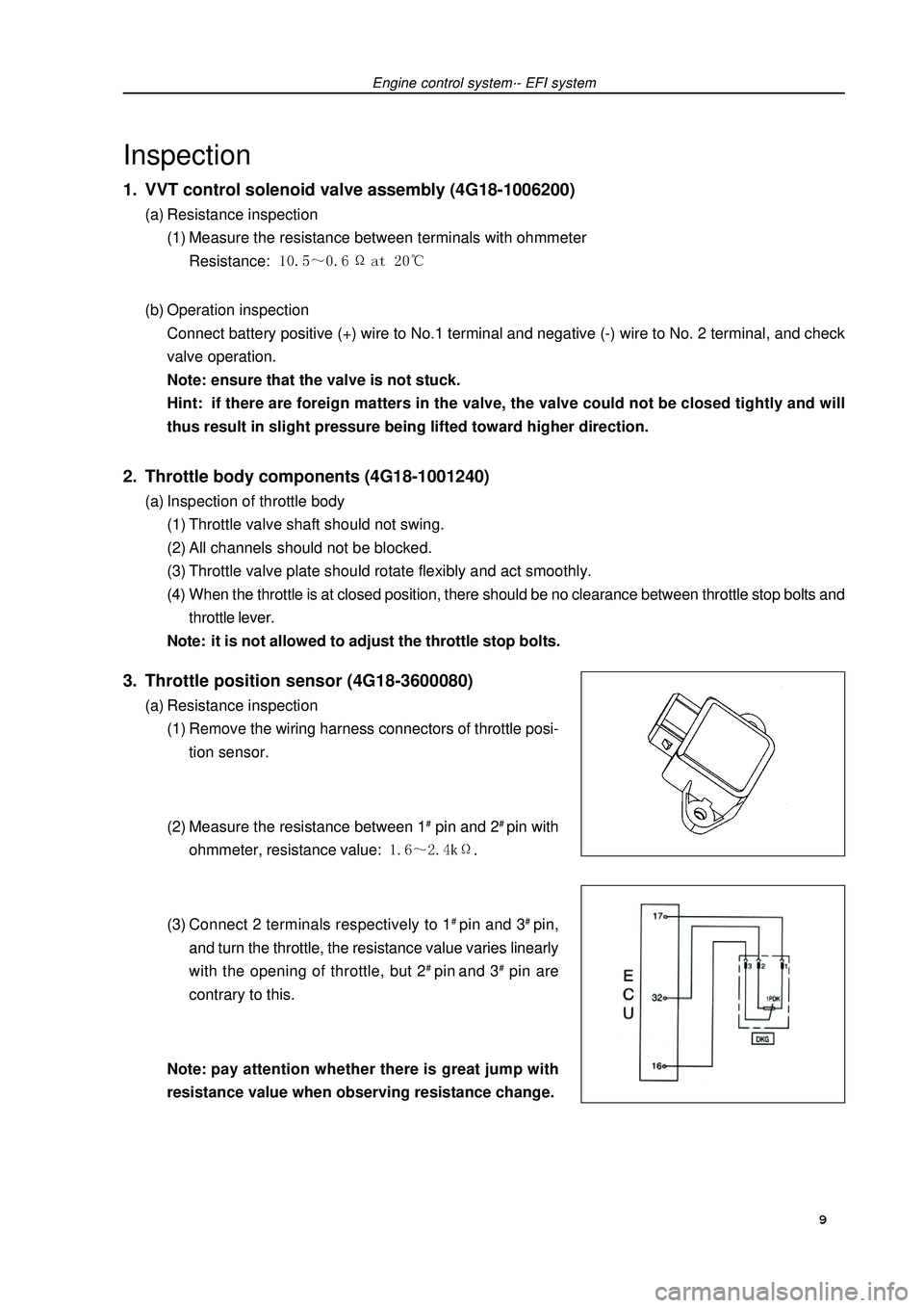
Note: it is not allowed to adjust the throttle stop bolts.3. Throttle position sensor (4G18-3600080)(a) Resistance inspection
(1) Remove the wiring harness connectors of throttle posi-
tion sensor.
(2) Measure the resistance between 1# pin and 2# pin with
ohmmeter, resistance value: .
(3) Connect 2 terminals respectively to 1# pin and 3# pin,
and turn the throttle, the resistance value varies linearly
with the opening of throttle, but 2# pin and 3# pin are
contrary to this.
Note:pay attention whether there is great jump with
resistance value when observing resistance change. 9
Page 23 of 419
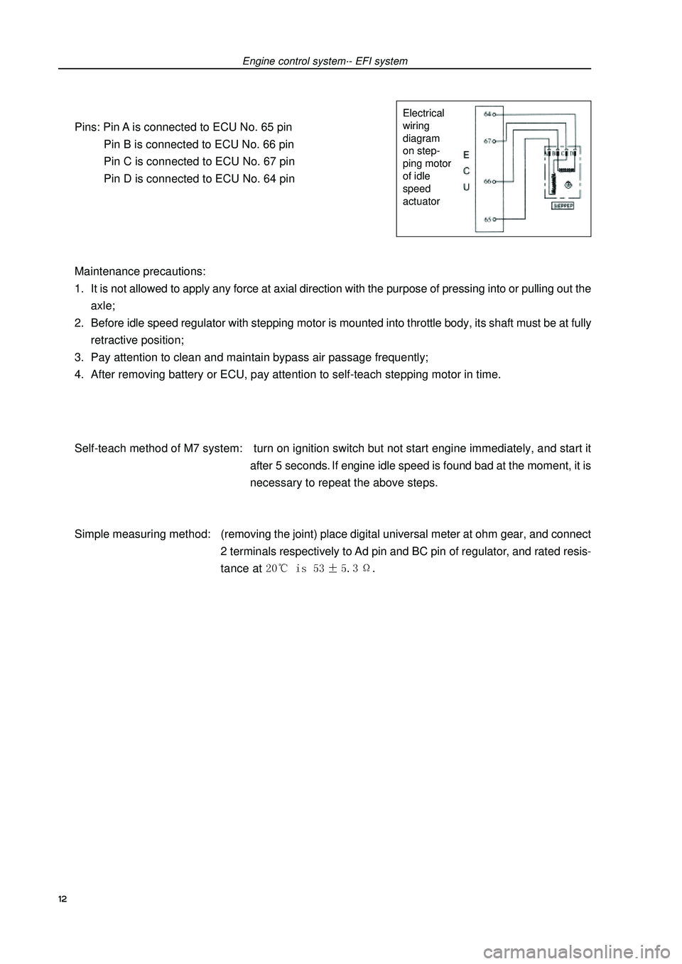
Pins: Pin A is connected to ECU No. 65 pin
Pin B is connected to ECU No. 66 pin
Pin C is connected to ECU No. 67 pin
Pin D is connected to ECU No. 64 pin
Maintenance precautions:
1. It is not allowed to apply any force at axial direction with the purpose of pressing into or pulling out the
axle;
2. Before idle speed regulator with stepping motor is mounted into throttle body, its shaft must be at fully
retractive position;
3. Pay attention to clean and maintain bypass air passage frequently;
4. After removing battery or ECU, pay attention to self-teach stepping motor in time.
Self-teach method of M7 system: turn on ignition switch but not start engine immediately, and start it
after 5 seconds. If engine idle speed is found bad at the moment, it is
necessary to repeat the above steps.
Simple measuring method:(removing the joint) place digital universal meter at ohm gear, and connect
2 terminals respectively to Ad pin and BC pin of regulator, and rated resis-
tance at Engine control system·- EFI systemElectrical
wiring
diagram
on step-
ping motor
of idle
speed
actuator12
Page 25 of 419
FuelFuel systemPrecautions1. Before repairing fuel system, uncouple battery negative (-) wire at first.
2. When operating on fuel system, do not smoke or repair near fire area.
3. Do not let gasoline come into contact with rubber or leather parts.
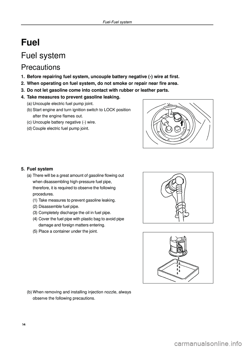
4. Take measures to prevent gasoline leaking.(a) Uncouple electric fuel pump joint.
(b) Start engine and turn ignition switch to LOCK position
after the engine flames out.
(c) Uncouple battery negative (-) wire.
(d) Couple electric fuel pump joint.5. Fuel system(a) There will be a great amount of gasoline flowing out
when disassembling high-pressure fuel pipe,
therefore, it is required to observe the following
procedures.
(1) Take measures to prevent gasoline leaking.
(2) Disassemble fuel pipe.
(3) Completely discharge the oil in fuel pipe.
(4) Cover the fuel pipe with plastic bag to avoid pipe
damage and foreign matters entering.
(5) Place a container under the joint.
(b) When removing and installing injection nozzle, always
observe the following precautions.Fuel-Fuel system 14
Page 26 of 419
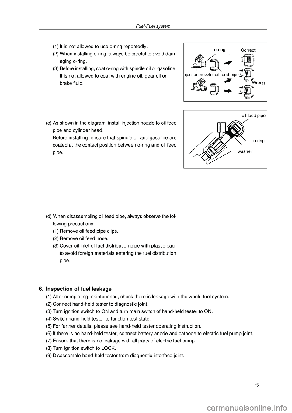
Fuel-Fuel system(1) It is not allowed to use o-ring repeatedly.
(2) When installing o-ring, always be careful to avoid dam-
aging o-ring.
(3) Before installing, coat o-ring with spindle oil or gasoline.
It is not allowed to coat with engine oil, gear oil or
brake fluid.
(c) As shown in the diagram, install injection nozzle to oil feed
pipe and cylinder head.
Before installing, ensure that spindle oil and gasoline are
coated at the contact position between o-ring and oil feed
pipe.
(d) When disassembling oil feed pipe, always observe the fol-
lowing precautions.
(1) Remove oil feed pipe clips.
(2) Remove oil feed hose.
(3) Cover oil inlet of fuel distribution pipe with plastic bag
to avoid foreign materials entering the fuel distribution
pipe.injection nozzle6. Inspection of fuel leakage(1) After completing maintenance, check there is leakage with the whole fuel system.
(2) Connect hand-held tester to diagnostic joint.
(3) Turn ignition switch to ON and turn main switch of hand-held tester to ON.
(4) Switch hand-held tester to function test state.
(5) For further details, please see hand-held tester operating instruction.
(6) If there is no hand-held tester, connect battery anode and cathode to electric fuel pump joint.
(7) Ensure that there is no leakage with all parts of electric fuel pump.
(8) Turn ignition switch to LOCK.
(9) Disassemble hand-held tester from diagnostic interface joint.15o-ringoil feed pipeoil feed pipeo-ringwasherCorrect
Wrong
Page 27 of 419
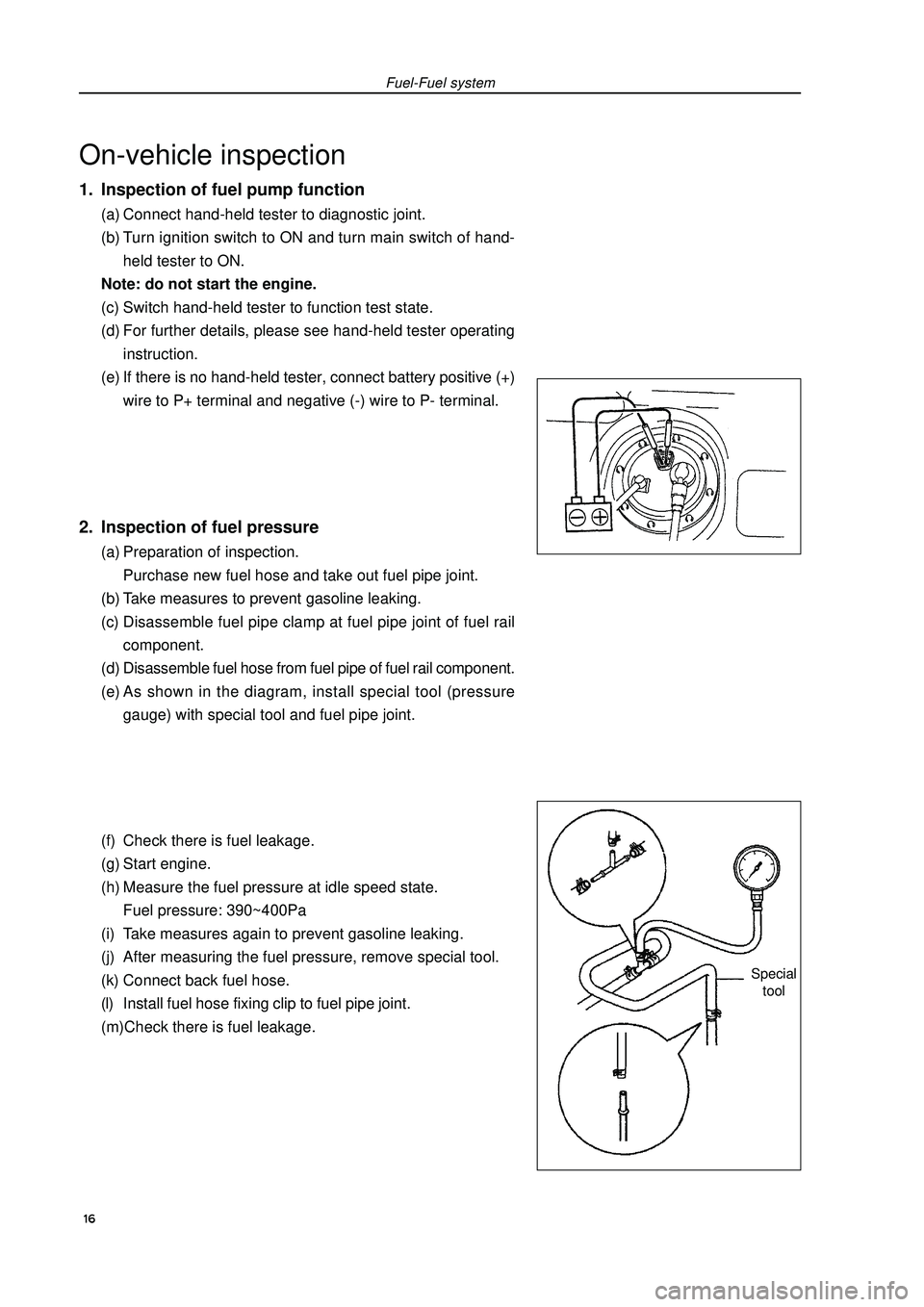
On-vehicle inspection1. Inspection of fuel pump function(a) Connect hand-held tester to diagnostic joint.
(b) Turn ignition switch to ON and turn main switch of hand-
held tester to ON.
Note: do not start the engine.
(c) Switch hand-held tester to function test state.
(d) For further details, please see hand-held tester operating
instruction.
(e) If there is no hand-held tester, connect battery positive (+)
wire to P+ terminal and negative (-) wire to P- terminal.2. Inspection of fuel pressure(a) Preparation of inspection.
Purchase new fuel hose and take out fuel pipe joint.
(b) Take measures to prevent gasoline leaking.
(c) Disassemble fuel pipe clamp at fuel pipe joint of fuel rail
component.
(d) Disassemble fuel hose from fuel pipe of fuel rail component.
(e) As shown in the diagram, install special tool (pressure
gauge) with special tool and fuel pipe joint.
(f) Check there is fuel leakage.
(g) Start engine.
(h) Measure the fuel pressure at idle speed state.
Fuel pressure: 390~400Pa
(i) Take measures again to prevent gasoline leaking.
(j) After measuring the fuel pressure, remove special tool.
(k) Connect back fuel hose.
(l) Install fuel hose fixing clip to fuel pipe joint.
(m)Check there is fuel leakage.Fuel-Fuel systemSpecial
tool 16
Page 28 of 419
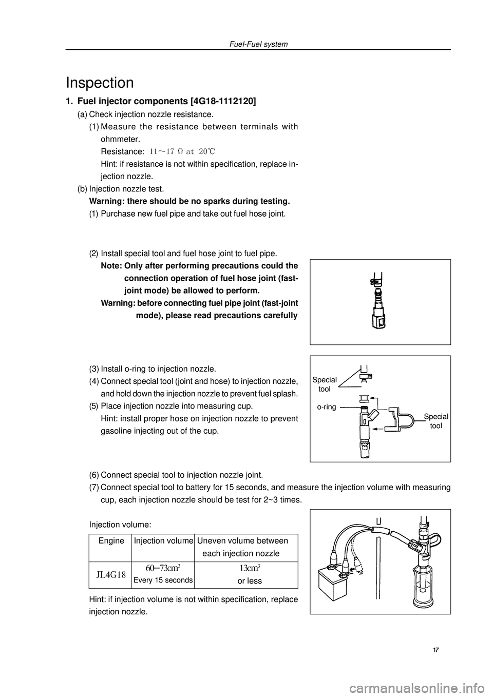
(6) Connect special tool to injection nozzle joint.
(7) Connect special tool to battery for 15 seconds, and measure the injection volume with measuring
cup, each injection nozzle should be test for 2~3 times.
Injection volume:Fuel-Fuel systemInspection1. Fuel injector components [4G18-1112120](a) Check injection nozzle resistance.
(1) Measure the resistance between terminals with
ohmmeter.
Resistance: Hint: if resistance is not within specification, replace in-
jection nozzle.
(b) Injection nozzle test.
Warning: there should be no sparks during testing.
(1) Purchase new fuel pipe and take out fuel hose joint.
(2) Install special tool and fuel hose joint to fuel pipe.
Note: Only after performing precautions could the
connection operation of fuel hose joint (fast-
joint mode) be allowed to perform.
Warning: before connecting fuel pipe joint (fast-joint
mode), please read precautions carefully
(3) Install o-ring to injection nozzle.
(4) Connect special tool (joint and hose) to injection nozzle,
and hold down the injection nozzle to prevent fuel splash.
(5) Place injection nozzle into measuring cup.
Hint: install proper hose on injection nozzle to prevent
gasoline injecting out of the cup.
Engine Injection volume Uneven volume between
each injection nozzleEvery 15 secondsor lessHint: if injection volume is not within specification, replace
injection nozzle. 17 Special
toolSpecial
toolo-ring
Page 36 of 419
 Blow air into valve from cylinder side and check the air is
easy to get through.
Warning: do not suck against th GEELY FC 2008 Workshop Manual Exhaust gas control - Exhaust gas control system3. PCV valve assembly [4G18-1014110](a) Blow air into valve from cylinder side and check the air is
easy to get through.
Warning: do not suck against th](/manual-img/58/57161/w960_57161-35.png)
Exhaust gas control - Exhaust gas control system3. PCV valve assembly [4G18-1014110](a) Blow air into valve from cylinder side and check the air is
easy to get through.
Warning: do not suck against the valve, because the
gasoline left in the valve will make you be
injured.
(b) Blow air into valve from intake manifold side and check
the air is hard to get through.
Hint: if the function does not conform to the standard, PCV
valve should be replaced.Inspection1. Carbon canister assembly [4G18-1129020]Carbonl canister assembly. Check the function of carbon can-
ister according to the following tables.
Standard:2. Carbon canister control valve(a) For carbon canister control valve, check the conduction be-
tween terminals.
Resistance: (b) Check the control valve operates.
(1) Supply battery voltage to its terminal.
(2) Check air is flown as the arrow direction on valve body. 25Inspection Methods Standard
Close B hole and C hole and then
supply vacuum to A hole No leakage
Close C hole and then supply vacuum Air flown out
to A hole from B hole
Close C hole and then blow air Air flown out
into A hole from B hole
Blow air into A hole Air flown out from B hole
and C holeClean hose Cylinder side
Intake manifold side