Page 37 of 419
![GEELY FC 2008 Workshop Manual Engine mechanismEngine assemblyInspection1. Check coolant.
2. Check engine oil.
3. Check battery.
4. Check air filter assembly.
5. Check spark plug [4G18-3705113].
6. Check drive belt [4G18-1307107].H GEELY FC 2008 Workshop Manual Engine mechanismEngine assemblyInspection1. Check coolant.
2. Check engine oil.
3. Check battery.
4. Check air filter assembly.
5. Check spark plug [4G18-3705113].
6. Check drive belt [4G18-1307107].H](/manual-img/58/57161/w960_57161-36.png)
Engine mechanismEngine assemblyInspection1. Check coolant.
2. Check engine oil.
3. Check battery.
4. Check air filter assembly.
5. Check spark plug [4G18-3705113].
6. Check drive belt [4G18-1307107].Hint: do not check belt tension, because automatic tensioner is applied.7. Check ignition timing.(a) Warm up engine.
(b) Connect timing lamp to engine.
(c) Check ignition timing at idle speed.
Ignition timing: before top dead center Note: when checking ignition timing, place
transmission at neutral position.
Hint: After run the engine for 5 seconds with rotating
speed of 1000-1300rpm, check the engine could
recover to idle running.8. Check engine idle speed.(a) Warm up engine and run it at idle speed.
(b) Read engine rotating number in data flow with diagnostic instrument.
(c) Check idle speed.
Idle speed: about 750-850rpm
Notes:When checking idle speed, place cooling fan at OFF position.Turn off all auxiliary devices and air conditioner.Engine mechanism - Engine assemblyK-line 26
Page 38 of 419
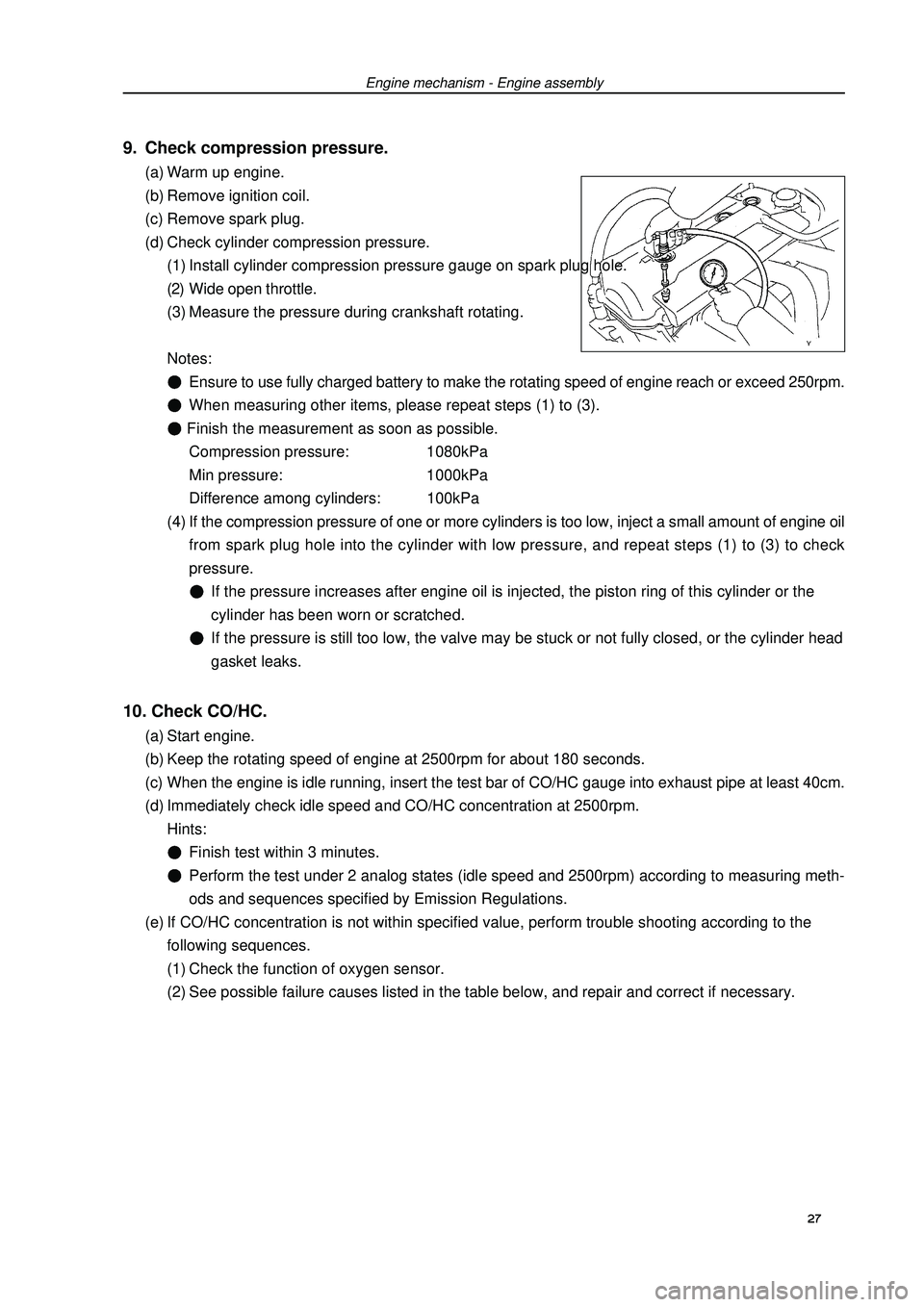
9. Check compression pressure.(a) Warm up engine.
(b) Remove ignition coil.
(c) Remove spark plug.
(d) Check cylinder compression pressure.
(1) Install cylinder compression pressure gauge on spark plug hole.
(2) Wide open throttle.
(3) Measure the pressure during crankshaft rotating.
Notes:Ensure to use fully charged battery to make the rotating speed of engine reach or exceed 250rpm.When measuring other items, please repeat steps (1) to (3). Finish the measurement as soon as possible.
Compression pressure: 1080kPa
Min pressure: 1000kPa
Difference among cylinders: 100kPa
(4) If the compression pressure of one or more cylinders is too low, inject a small amount of engine oil
from spark plug hole into the cylinder with low pressure, and repeat steps (1) to (3) to check
pressure.If the pressure increases after engine oil is injected, the piston ring of this cylinder or the
cylinder has been worn or scratched.If the pressure is still too low, the valve may be stuck or not fully closed, or the cylinder head
gasket leaks.10. Check CO/HC.(a) Start engine.
(b) Keep the rotating speed of engine at 2500rpm for about 180 seconds.
(c) When the engine is idle running, insert the test bar of CO/HC gauge into exhaust pipe at least 40cm.
(d) Immediately check idle speed and CO/HC concentration at 2500rpm.
Hints:Finish test within 3 minutes.Perform the test under 2 analog states (idle speed and 2500rpm) according to measuring meth-
ods and sequences specified by Emission Regulations.
(e) If CO/HC concentration is not within specified value, perform trouble shooting according to the
following sequences.
(1) Check the function of oxygen sensor.
(2) See possible failure causes listed in the table below, and repair and correct if necessary.Engine mechanism - Engine assembly27
Page 47 of 419
Engine mechanism - Engine assemblyEngine assemblyReplacement1. Take measures to prevent gasoline leaking.
2. Remove engine right bottom shield.
3. Remove engine left bottom shield.
4. Discharge coolant.
5. Remove front wheels.
6. Remove engine plastic hood components.
7. Remove battery.
8. Remove air filter assembly.
9. Remove air filter hose.
10. Remove battery tray.
11. Disassemble fuel hose assembly.
12. Remove throttle cable assembly.
13. Disassemble radiator hose inlet end.
14. Disassemble radiator hose outlet end.
15. Disassemble cold air pipe inlet hose.
16. Disassemble cold air pipe outlet hose.
17. Remove transmission control pull cable assembly.
18. Disassemble warm air water inlet hose [4G18-1300102].
19. Disassemble warm air water outlet hose [4G18-1300108].
20. Disassemble the hoses of all joints to connect vehicle body end.
21. Uncouple engine wire harness.(a) Remove glove compartment door.
(b) Remove engine wire harness from engine ECU and junction block.
(c) Pull out engine wire harness.
(b) Remove engine wire harness from junction block of engine room.
(e) Remove vehicle body earth wire. 36
Page 54 of 419
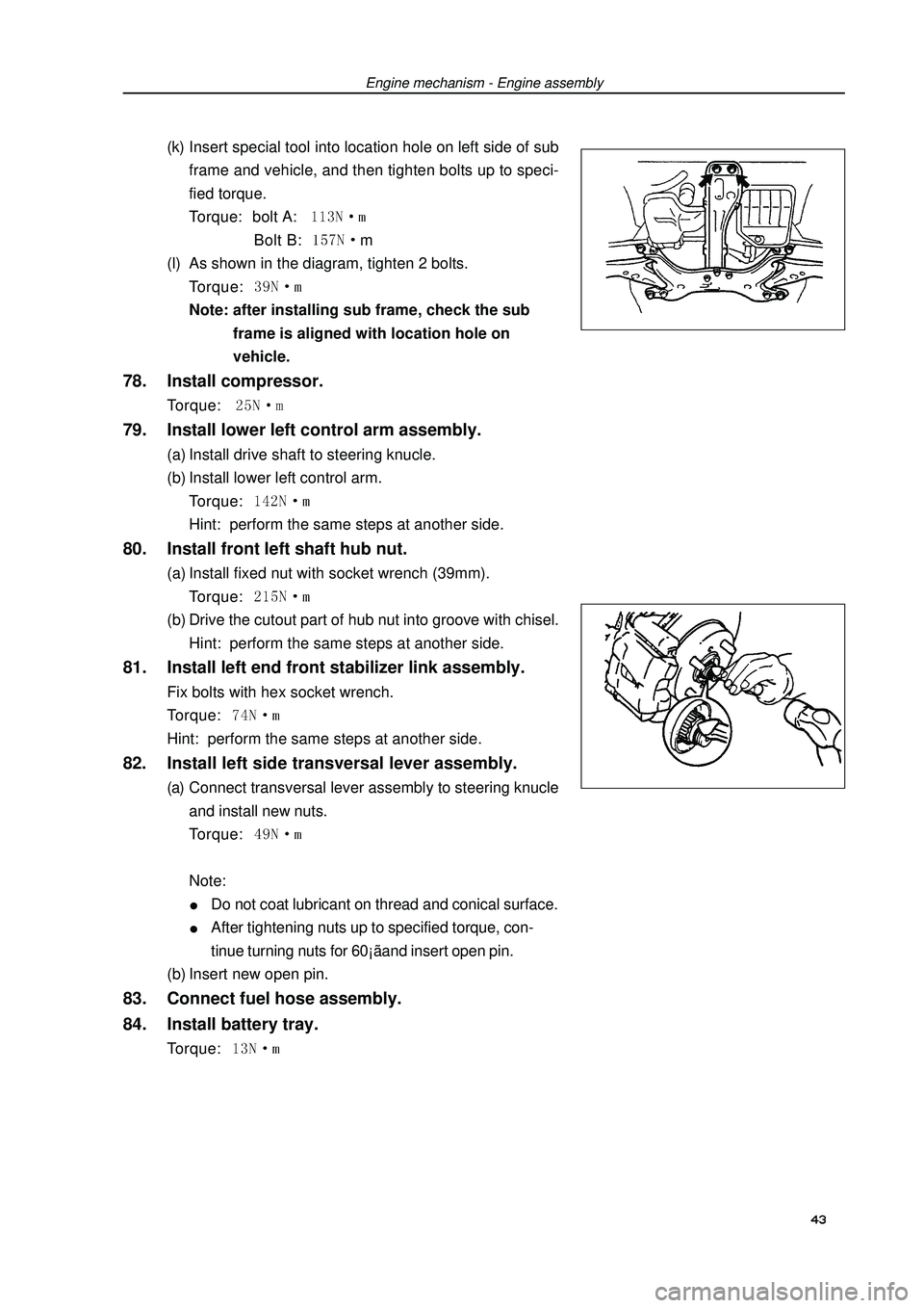
(k) Insert special tool into location hole on left side of sub
frame and vehicle, and then tighten bolts up to speci-
fied torque.
Torque: bolt A: Bolt B: m
(l) As shown in the diagram, tighten 2 bolts.
Torque: Note: after installing sub frame, check the sub
frame is aligned with location hole on
vehicle.78. Install compressor.Torque: 79. Install lower left control arm assembly.(a) Install drive shaft to steering knucle.
(b) Install lower left control arm.
Torque: Hint: perform the same steps at another side.80. Install front left shaft hub nut.(a) Install fixed nut with socket wrench (39mm).
Torque: (b) Drive the cutout part of hub nut into groove with chisel.
Hint: perform the same steps at another side.81. Install left end front stabilizer link assembly.Fix bolts with hex socket wrench.
Torque: Hint: perform the same steps at another side.82. Install left side transversal lever assembly.(a) Connect transversal lever assembly to steering knucle
and install new nuts.
Torque: Note:Do not coat lubricant on thread and conical surface.After tightening nuts up to specified torque, con-
tinue turning nuts for 60¡ãand insert open pin.
(b) Insert new open pin.83. Connect fuel hose assembly.
84. Install battery tray.Torque: Engine mechanism - Engine assembly 43
Page 55 of 419
Engine mechanism - Engine assembly85. Install alternator mounting components.Torque: 12mm bolt head A: 14mm bolt head B: 86. Install drive belt.
87. Install engine wire harness and all hoses
not connected.(a) Check and connect all joints of engine wire harness.
(b) Check and connect all hoses.88. Install transmission control pull cable assembly
and valve control pull cable.
89. Install air filter assembly and its hose.
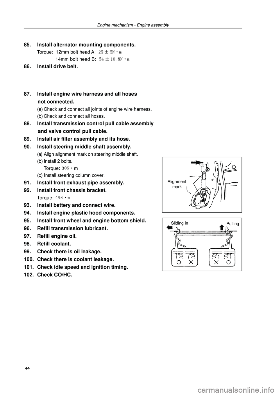
90. Install steering middle shaft assembly.(a) Align alignment mark on steering middle shaft.
(b) Install 2 bolts.
Torque: m
(c) Install steering column cover.91. Install front exhaust pipe assembly.
92. Install front chassis bracket.Torque: 93. Install battery and connect wire.
94. Install engine plastic hood components.
95. Install front wheel and engine bottom shield.
96. Refill transmission lubricant.
97. Refill engine oil.
98. Refill coolant.
99. Check there is oil leakage.
100. Check there is coolant leakage.
101. Check idle speed and ignition timing.
102. Check CO/HC.Alignment
mark
Sliding in
Pulling 44
Page 79 of 419
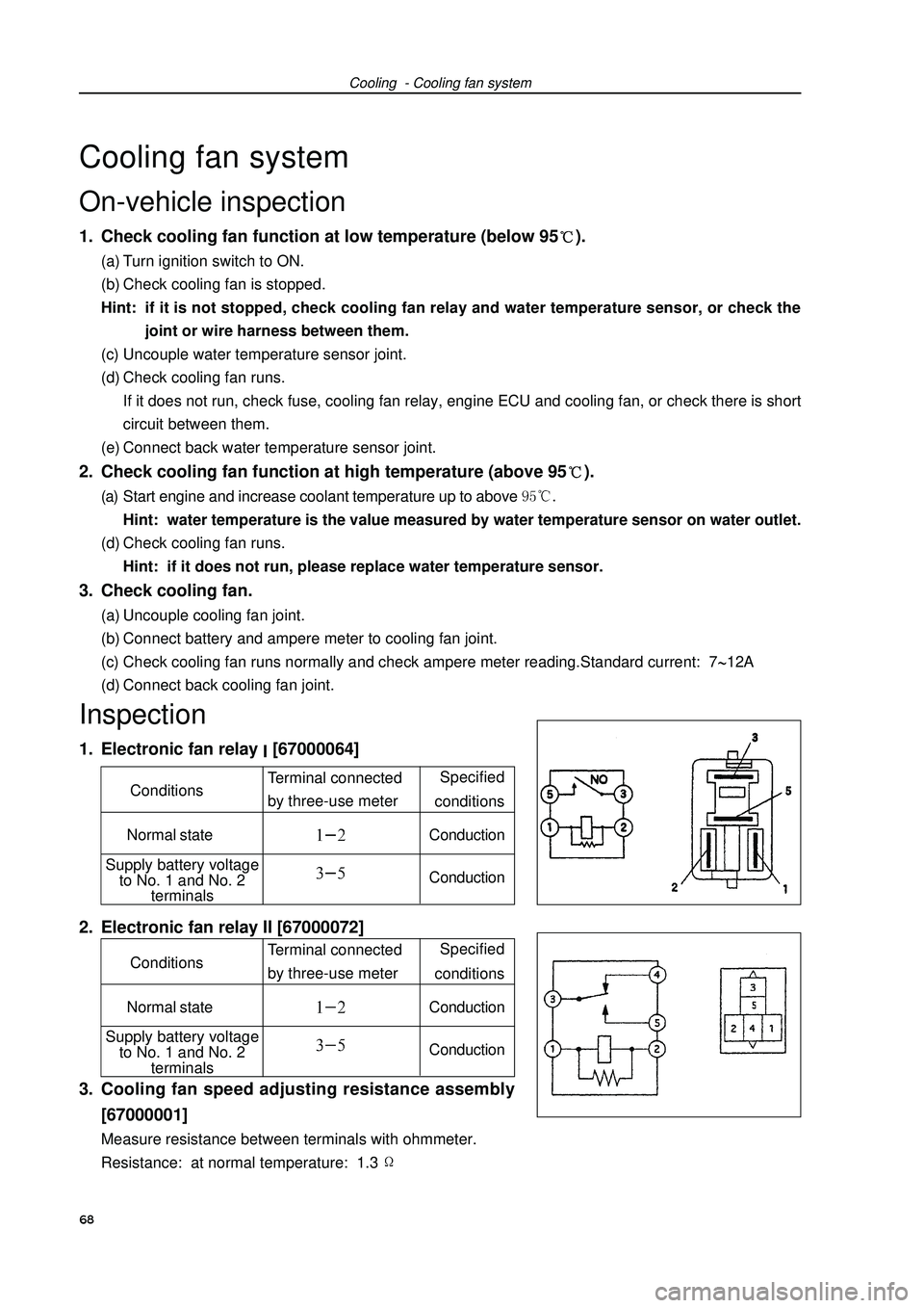
Cooling - Cooling fan systemCooling fan systemOn-vehicle inspection1. Check cooling fan function at low temperature (below 95).(a) Turn ignition switch to ON.
(b) Check cooling fan is stopped.
Hint: if it is not stopped, check cooling fan relay and water temperature sensor, or check the
joint or wire harness between them.
(c) Uncouple water temperature sensor joint.
(d) Check cooling fan runs.
If it does not run, check fuse, cooling fan relay, engine ECU and cooling fan, or check there is short
circuit between them.
(e) Connect back water temperature sensor joint.2. Check cooling fan function at high temperature (above 95).(a) Start engine and increase coolant temperature up to above Hint: water temperature is the value measured by water temperature sensor on water outlet.
(d) Check cooling fan runs.
Hint: if it does not run, please replace water temperature sensor.3. Check cooling fan.(a) Uncouple cooling fan joint.
(b) Connect battery and ampere meter to cooling fan joint.
(c) Check cooling fan runs normally and check ampere meter reading.Standard current: 712A
(d) Connect back cooling fan joint.Inspection1. Electronic fan relay [67000064]
2. Electronic fan relay II [67000072]
3. Cooling fan speed adjusting resistance assembly
[67000001]Measure resistance between terminals with ohmmeter.
Resistance: at normal temperature: 1.368 Specified
conditions
Normal stateConductionConductionTerminal connected
by three-use meter Conditions
Supply battery voltage
to No. 1 and No. 2
terminals
Specified
conditions
Normal stateConductionConductionTerminal connected
by three-use meter Conditions
Supply battery voltage
to No. 1 and No. 2
terminals
Page 90 of 419
Starting and charging - Starting systemStarting and chargingStarting systemInspection1. Starter installation componentsNote: this test must be finished within 3 to 5 seconds to
avoid burning out coil.
(a) Remove nut at C terminal to uncouple wire of field coil.
(b) As shown in the diagram, connect battery wire to electro-
magnetic switch, and check drive pinion is pushed outside,
(pull-in coil and hold-in coil).
(c) As shown in the diagram, uncouple negative wire from ter-
minal C after the above connections, and check drive pin-
ion is still at the state of being pushed outside.(Hold-in coil)
(d) Push drive pinion toward armature side, and measure the
clearance between drive pinion end and stop ring.
Standard clearance: 1.0~5.0mm
(e) Uncouple negative wire from electromagnetic switch
housing, and check drive pinion returns back to original
position toward inside.79Terminal C
Terminal 50Terminal C
Terminal 50Terminal C
Terminal 50
Page 91 of 419
Starting and charging - Starting system(f) Connect magnetic field coil wire to terminal C.
(h) Torque: (i) Clamp starter with jaw vice.
(j) As shown in the diagram, connect battery with ampere
meter.
(k) Read current value displayed on ampere meter.
(l) Current value specification: 90 A or lower at 11.5 V.2. Starter relay80Terminal 50Terminal 30Ampere
meter Specified
conditions
Normal stateConductionConductionTerminal connected
by three-use meter Conditions
Supply battery voltage
to No. 1 and No. 2
terminals