2008 GEELY FC air condition
[x] Cancel search: air conditionPage 3 of 419

Preface
Geely “FC” is an automobile with high performance/price ratio and it meets the requirement
of national safety, energy saving, emission regulations and personal use. This automobile is
a completely new and excellent model produced by Zhejiang Geely Automobile Co., Ltd with
development in self-reliance of Geely group and with self-dominated intellectual property
right. It characterizes elegant appearance,
energy conservation and environmental protection,
safety and comfort. “FC” is a product opening a completely new viewpoint of automobile
selection, because it is developed on the basis of creative design thinking that breaks through
all established customs and it features perfectly balanced performance of power, space,
safety, manipulation and comfort. “FC” is a competitive product for Geely developing brand
and exploring mid-level automobile market, which takes over the company philosophy “make
good cars that common people can afford, and let Geely cars go to the whole world” of Geely
automobile. “FC” is combination of creativity and intelligence of quite a large number of
automobile experts, who have been developing and searching with great concentration for
more than 30 months, and it fully embodies persistent Geely style of fashion appearance
and high performance/price ratio.
“FC” is equipped with engine JL4G18 completely developed and produced by Geely group.
Engine JL4G18 applies the following advanced technology such as VVT, full aluminum cylin-
der body, plastic intake manifold, completely new VVT inside seal method, completely new
OCV valve filtering method etc. with M7.9.7 electric injection system of BOSCH, and its
index on power efficiency, economical efficiency, and safety efficiency etc. reaches leading
level of national model with the same type. This engine features strong power, low fuel
consumption, low noise and high power per liter etc.
We start to compile “FC” Automobile Maintenance Manual, which is divided into 27 sec-
tions with detailed description of overall structure and maintenance of engine 4G18.VVT;
inspection and repair of engine BOSCH M7.9.7 electric control fuel injection system; struc-
ture and maintenance of chassis; structure and maintenance of FC electrical equipment;
structure and maintenance of ABS anti-lock brake system; structure and maintenance of
SRS air bag; structure and maintenance of auto air conditioning system; structure and main-
tenance of vehicle body etc. Information is detailed and accurate, contents are in systematic
coherence and description is concise and comprehensive.
This manual is compiled from structure, which prompts “FC” service personnel to master
Page 8 of 419

Brake
Brake system......................................................
132
Notes..............................................................
132
Remove malfunction...........................................
133
Malfunction phenomenon table.....................
133
Brake liquid.........................................................
135
Discharge the air in brake system.................
135
Brake pedal assembly........................................
136
Adjustment.....................................................
136
Change..........................................................
137
Vacuum booster assembly.................................
138
Inspection on automobile...............................
138
Change..........................................................
138
Front brake assembly.........................................
141
Overhaul........................................................
141
Rear brake assembly.........................................
144
Overhaul........................................................
144Hydraulic pressure control unit (equipping with ABS)...148
Inspection on automobile...............................
148
Change..........................................................
148
Speed sensor of front wheel..............................
151
Change..........................................................
151
Speed sensor of rear wheels...........................
152
Change..........................................................
152
Parking brake
Parking brake system.........................................
154
Malfunction phenomenon table.....................
154
Adjustment.....................................................
154
Parking brake handle assembly.........................
155
Change..........................................................
155
Parking front bake pull cable assembly............
156
Change..........................................................
156
Parking rear brake pull cable assembly...........
158
Change..........................................................
158
Parking brake assembly....................................
161
Overhaul........................................................
161Transmission
Disassemble assembly...................................
165
Assemble the assembly....................................
191
Steering column
Steering system..................................................
192
Note...............................................................
192
Malfunction phenomenon table.....................
192
Inspection on automobile...............................
193
Steering column system.....................................
194
Overhaul........................................................
194
Power steering
Power steering system......................................
198
Note...............................................................
198
Malfunction phenomenon table....................
199
Inspection on automobile.............................
200
Power steering oil pump assembly..................
203
Overhaul........................................................
203
Power steering gear assembly.........................
205
Overhaul........................................................
205
Air conditioner
Air conditioning system......................................
213
Note...............................................................
213
Inspection on automobile...............................
213
Inspection......................................................
214
Refrigerant..........................................................
215
Inspection on automobile...............................
215
Change..........................................................
221
Refrigerant pipeline............................................
222
Parts...............................................................
222Control assembly, air conditioner control panel (AUTO A/C)...223
Overhaul........................................................
223
Fan assembly...................................................
224
Overhaul........................................................
224
Air conditioner central heating core assembly..
227
Overhaul........................................................
227
Compressor assembly.....................................
234
Page 16 of 419

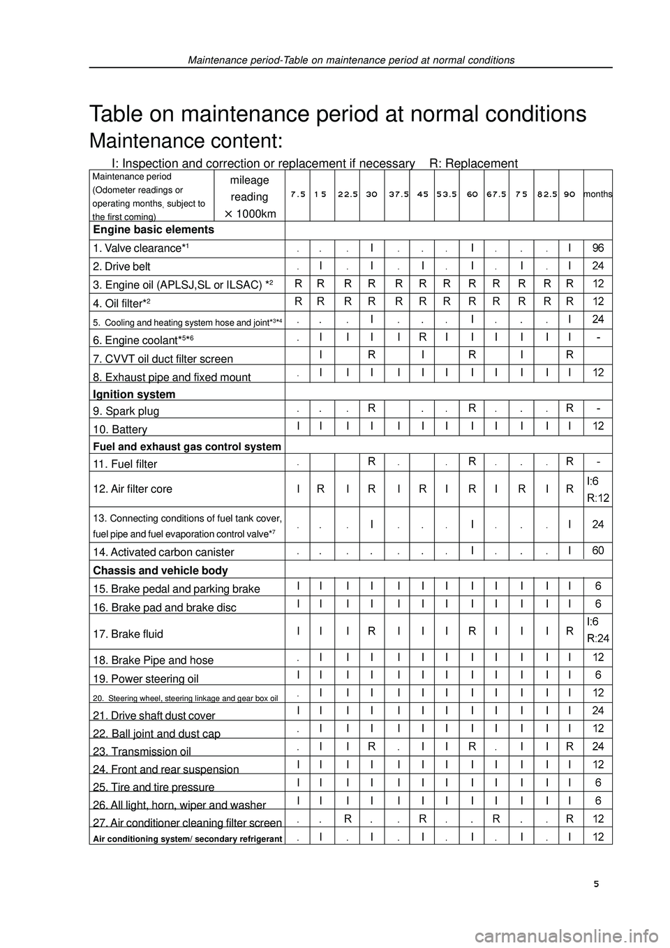
Maintenance period-Table on maintenance period at normal conditionsTable on maintenance period at normal conditionsMaintenance content:I: Inspection and correction or replacement if necessary R: Replacementmileage
reading1000kmMaintenance period
(Odometer readings or
operating monthssubject to
the first coming)Engine basic elements
1. Valve clearance*12. Drive belt
3. Engine oil (APLSJ,SL or ILSAC) *24. Oil filter*25. Cooling and heating system hose and joint*3*46. Engine coolant*5*67. CVVT oil duct filter screen
8. Exhaust pipe and fixed mount
Ignition system
9. Spark plug
10. BatteryFuel and exhaust gas control system11. Fuel filter
12. Air filter core13. Connecting conditions of fuel tank cover,
fuel pipe and fuel evaporation control valve*714. Activated carbon canister
Chassis and vehicle body
15. Brake pedal and parking brake
16. Brake pad and brake disc
17. Brake fluid
18. Brake Pipe and hose
19. Power steering oil20. Steering wheel, steering linkage and gear box oil21. Drive shaft dust cover
22. Ball joint and dust cap
23. Transmission oil
24. Front and rear suspension
25. Tire and tire pressure
26. All light, horn, wiper and washer
27. Air conditioner cleaning filter screenAir conditioning system/ secondary refrigerant7 . 5 1 5 22.5 3037.5 4553.5 60 67.5 7 582.5 90months 5
Page 18 of 419

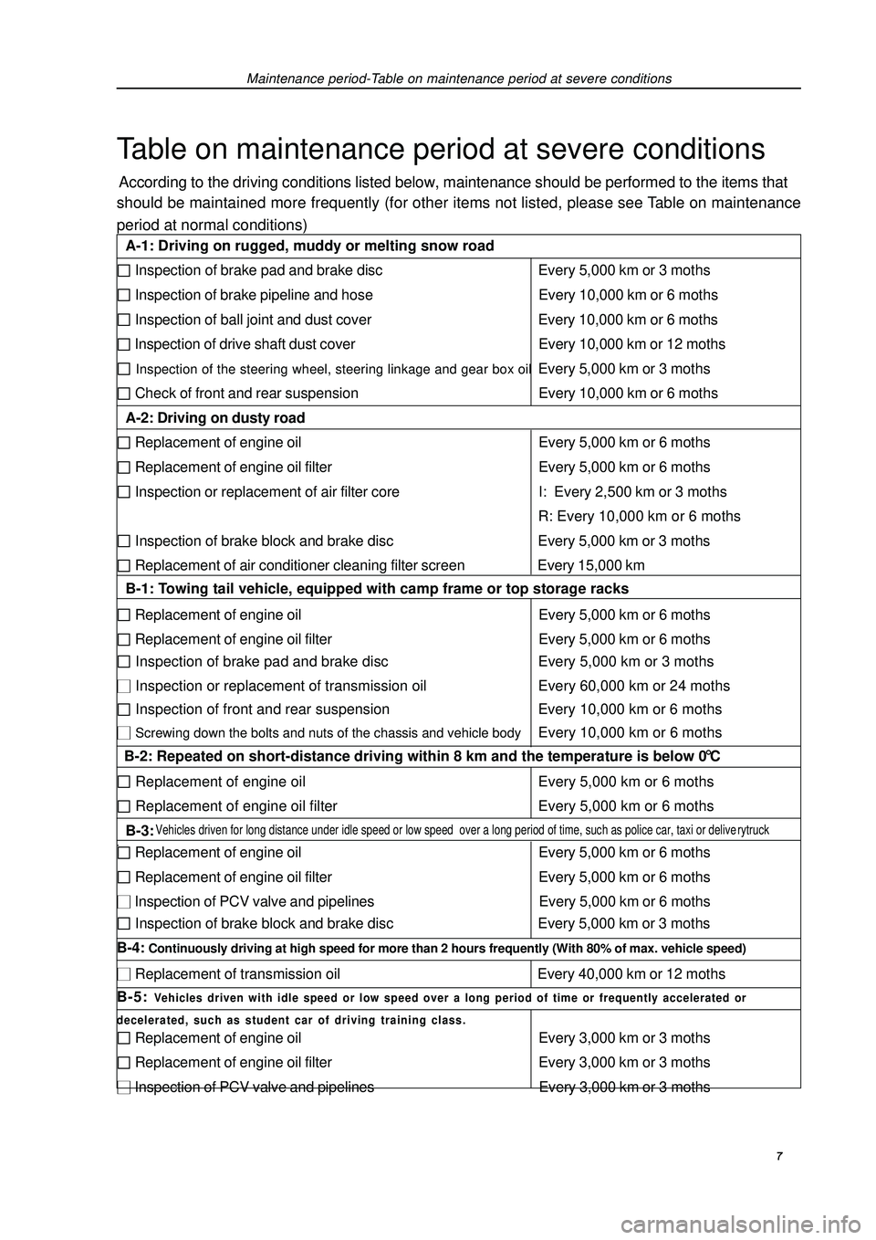
Maintenance period-Table on maintenance period at severe conditionsTable on maintenance period at severe conditionsAccording to the driving conditions listed below, maintenance should be performed to the items that
should be maintained more frequently (for other items not listed, please see Table on maintenance
period at normal conditions) 7 A-1: Driving on rugged, muddy or melting snow road Inspection of brake pad and brake disc Every 5,000 km or 3 moths Inspection of brake pipeline and hose Every 10,000 km or 6 moths Inspection of ball joint and dust cover Every 10,000 km or 6 moths Inspection of drive shaft dust cover Every 10,000 km or 12 moths Inspection of the steering wheel, steering linkage and gear box oilEvery 5,000 km or 3 moths Check of front and rear suspension Every 10,000 km or 6 moths
A-2: Driving on dusty road Replacement of engine oil Every 5,000 km or 6 moths Replacement of engine oil filter Every 5,000 km or 6 moths Inspection or replacement of air filter core I: Every 2,500 km or 3 moths
R: Every 10,000 km or 6 moths Inspection of brake block and brake disc Every 5,000 km or 3 moths Replacement of air conditioner cleaning filter screen Every 15,000 km
B-1: Towing tail vehicle, equipped with camp frame or top storage racks Replacement of engine oil Every 5,000 km or 6 moths Replacement of engine oil filter Every 5,000 km or 6 moths Inspection of brake pad and brake disc Every 5,000 km or 3 moths Inspection or replacement of transmission oil Every 60,000 km or 24 moths Inspection of front and rear suspension Every 10,000 km or 6 moths Screwing down the bolts and nuts of the chassis and vehicle bodyEvery 10,000 km or 6 moths
B-2: Repeated on short-distance driving within 8 km and the temperature is below 0 °C Replacement of engine oil Every 5,000 km or 6 moths Replacement of engine oil filter Every 5,000 km or 6 moths
B-3: Vehicles driven for long distance under idle speed or low speed over a long period of time, such as police car, taxi or deliverytruck. Replacement of engine oil Every 5,000 km or 6 moths Replacement of engine oil filter Every 5,000 km or 6 moths Inspection of PCV valve and pipelines Every 5,000 km or 6 moths Inspection of brake block and brake disc Every 5,000 km or 3 moths
B-4: Continuously driving at high speed for more than 2 hours frequently (With 80% of max. vehicle speed) Replacement of transmission oil Every 40,000 km or 12 moths
B-5: Vehicles driven with idle speed or low speed over a long period of time or frequently accelerated or
decelerated, such as student car of driving training class. Replacement of engine oil Every 3,000 km or 3 moths Replacement of engine oil filter Every 3,000 km or 3 moths Inspection of PCV valve and pipelines Every 3,000 km or 3 moths
Page 19 of 419

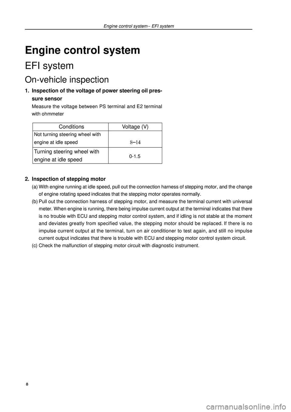
Engine control systemEFI systemOn-vehicle inspection1. Inspection of the voltage of power steering oil pres-
sure sensorMeasure the voltage between PS terminal and E2 terminal
with ohmmeter2. Inspection of stepping motor(a) With engine running at idle speed, pull out the connection harness of stepping motor, and the change
of engine rotating speed indicates that the stepping motor operates normally.
(b) Pull out the connection harness of stepping motor, and measure the terminal current with universal
meter. When engine is running, there being impulse current output at the terminal indicates that there
is no trouble with ECU and stepping motor control system, and if idling is not stable at the moment
and deviates greatly from specified value, the stepping motor should be replaced. If there is no
impulse current output at the terminal, turn on air conditioner to test again, and still no impulse
current output indicates that there is trouble with ECU and stepping motor control system circuit.
(c) Check the malfunction of stepping motor circuit with diagnostic instrument.Engine control system·- EFI system 8Conditions Voltage (V) Not turning steering wheel with
engine at idle speed Turning steering wheel with
engine at idle speed 0-1.5
Page 37 of 419
![GEELY FC 2008 Workshop Manual Engine mechanismEngine assemblyInspection1. Check coolant.
2. Check engine oil.
3. Check battery.
4. Check air filter assembly.
5. Check spark plug [4G18-3705113].
6. Check drive belt [4G18-1307107].H GEELY FC 2008 Workshop Manual Engine mechanismEngine assemblyInspection1. Check coolant.
2. Check engine oil.
3. Check battery.
4. Check air filter assembly.
5. Check spark plug [4G18-3705113].
6. Check drive belt [4G18-1307107].H](/manual-img/58/57161/w960_57161-36.png)
Engine mechanismEngine assemblyInspection1. Check coolant.
2. Check engine oil.
3. Check battery.
4. Check air filter assembly.
5. Check spark plug [4G18-3705113].
6. Check drive belt [4G18-1307107].Hint: do not check belt tension, because automatic tensioner is applied.7. Check ignition timing.(a) Warm up engine.
(b) Connect timing lamp to engine.
(c) Check ignition timing at idle speed.
Ignition timing: before top dead center Note: when checking ignition timing, place
transmission at neutral position.
Hint: After run the engine for 5 seconds with rotating
speed of 1000-1300rpm, check the engine could
recover to idle running.8. Check engine idle speed.(a) Warm up engine and run it at idle speed.
(b) Read engine rotating number in data flow with diagnostic instrument.
(c) Check idle speed.
Idle speed: about 750-850rpm
Notes:When checking idle speed, place cooling fan at OFF position.Turn off all auxiliary devices and air conditioner.Engine mechanism - Engine assemblyK-line 26
Page 67 of 419

Engine mechanism - CamshaftWarning: if the air pressure in timing advance side oil duct is released earlier than that in
timing delay side oil duct, VVT driver assembly will move suddenly toward
delay side.This will cause the damage of lock pin.
(g) Remove VVT drive fixed bolts.
Notes:
It is strictly forbidden to remove other 4 bolts.
Under the condition of repeating using camshaft
timing sprocket, release lock pin at first, and then
install sprocket.12. Install VVT driver assembly.
13. Install camshaft.Put VVT driver assembly together with intake camshaft.
(a) As shown in the diagram, gently make VVT assembly
hold camshaft and turn it toward left until straight pin is
inserted into groove.
Warning: it is strictly forbidden to turn camshaft
timing sprocket toward timing delay side
(toward right).
(b) Check there is no clearance between sprocket flange
and camshaft.
(c) Fix camshaft timing sprocket and then tighten flange
bolt.
Torque: 70 ±5N.m
(d) Check VVT driver assembly could move to timing
delay side and is locked at max. timing delay position.
(f) As shown in the diagram, align alignment mark with
timing mark on camshaft timing sprocket, and install
timing chain on the timing sprocket.
(g) Check forward mark and figure, and tighten bolts as
sequences shown in the diagram.
Torque: 13 ±0.78N.m
(h) Align alignment mark on the chain with timing mark on
camshaft timing sprocket, and place exhaust camshaft
in cylinder head.Straight pin
key
grooveFlange bolt
Straight pin56Timing remark
chain linkTiming mark
Timing remark chain link
Timing mark
Page 88 of 419

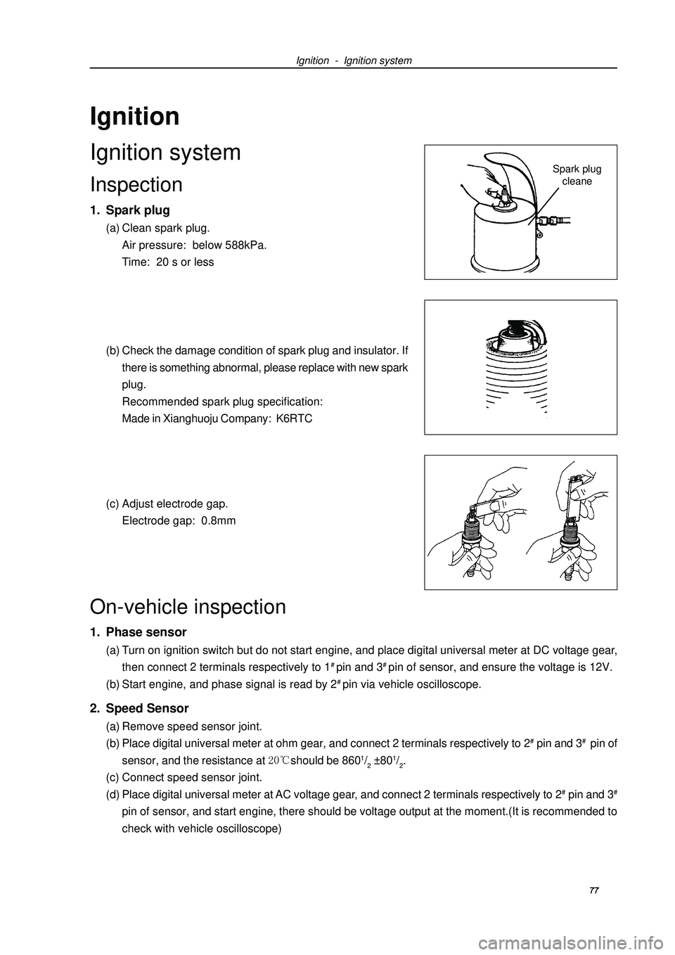
Ignition - Ignition systemSpark plug
cleaneOn-vehicle inspection1. Phase sensor(a) Turn on ignition switch but do not start engine, and place digital universal meter at DC voltage gear,
then connect 2 terminals respectively to 1# pin and 3# pin of sensor, and ensure the voltage is 12V.
(b) Start engine, and phase signal is read by 2# pin via vehicle oscilloscope.2. Speed Sensor(a) Remove speed sensor joint.
(b) Place digital universal meter at ohm gear, and connect 2 terminals respectively to 2# pin and 3# pin of
sensor, and the resistance at should be 8601/2 ±801/2.
(c) Connect speed sensor joint.
(d) Place digital universal meter at AC voltage gear, and connect 2 terminals respectively to 2# pin and 3#pin of sensor, and start engine, there should be voltage output at the moment.(It is recommended to
check with vehicle oscilloscope)IgnitionIgnition systemInspection1. Spark plug(a) Clean spark plug.
Air pressure: below 588kPa.
Time: 20 s or less
(b) Check the damage condition of spark plug and insulator. If
there is something abnormal, please replace with new spark
plug.
Recommended spark plug specification:
Made in Xianghuoju Company: K6RTC
(c) Adjust electrode gap.
Electrode gap: 0.8mm77