2008 GEELY FC tow
[x] Cancel search: towPage 15 of 419

Your precious automobile should be maintained according to maintenance period
at normal conditions (see table on maintenance period at normal conditions)If your precious automobile is mainly driven under one or more of the following conditions, some
maintenance items must be performed more frequently (see table on maintenance period at severe
conditions).A. Road conditions1. Driving on rugged, muddy or melting snow road.
2. Driving on dusty road.B. Driving conditions1. Towing tail vehicle, equipped with camp frame or top storage racks.
2. Repeated on short-distance driving within 8 km and the temperature is below 0.
3. Vehicles driven for long distance under idle speed or low speed over a long period of time,
such as police car, taxi or delivery truck.
4. Continuously driving at high speed for more than 2 hours frequently. (With 80% of max. ve-
hicle speed)
5. Vehicles driven with idle speed or low speed over a long period of time or frequently acceler-
ated or decelerated, such as training car of driving training class.Maintenance period-Regular maintenance itemsMaintenance periodRegular maintenance items 4
Page 18 of 419

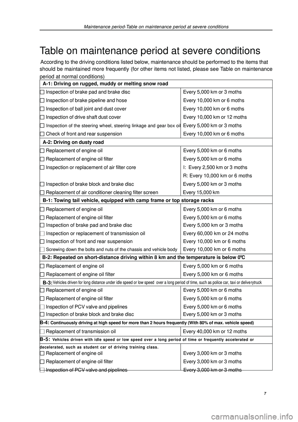
Maintenance period-Table on maintenance period at severe conditionsTable on maintenance period at severe conditionsAccording to the driving conditions listed below, maintenance should be performed to the items that
should be maintained more frequently (for other items not listed, please see Table on maintenance
period at normal conditions) 7 A-1: Driving on rugged, muddy or melting snow road Inspection of brake pad and brake disc Every 5,000 km or 3 moths Inspection of brake pipeline and hose Every 10,000 km or 6 moths Inspection of ball joint and dust cover Every 10,000 km or 6 moths Inspection of drive shaft dust cover Every 10,000 km or 12 moths Inspection of the steering wheel, steering linkage and gear box oilEvery 5,000 km or 3 moths Check of front and rear suspension Every 10,000 km or 6 moths
A-2: Driving on dusty road Replacement of engine oil Every 5,000 km or 6 moths Replacement of engine oil filter Every 5,000 km or 6 moths Inspection or replacement of air filter core I: Every 2,500 km or 3 moths
R: Every 10,000 km or 6 moths Inspection of brake block and brake disc Every 5,000 km or 3 moths Replacement of air conditioner cleaning filter screen Every 15,000 km
B-1: Towing tail vehicle, equipped with camp frame or top storage racks Replacement of engine oil Every 5,000 km or 6 moths Replacement of engine oil filter Every 5,000 km or 6 moths Inspection of brake pad and brake disc Every 5,000 km or 3 moths Inspection or replacement of transmission oil Every 60,000 km or 24 moths Inspection of front and rear suspension Every 10,000 km or 6 moths Screwing down the bolts and nuts of the chassis and vehicle bodyEvery 10,000 km or 6 moths
B-2: Repeated on short-distance driving within 8 km and the temperature is below 0 °C Replacement of engine oil Every 5,000 km or 6 moths Replacement of engine oil filter Every 5,000 km or 6 moths
B-3: Vehicles driven for long distance under idle speed or low speed over a long period of time, such as police car, taxi or deliverytruck. Replacement of engine oil Every 5,000 km or 6 moths Replacement of engine oil filter Every 5,000 km or 6 moths Inspection of PCV valve and pipelines Every 5,000 km or 6 moths Inspection of brake block and brake disc Every 5,000 km or 3 moths
B-4: Continuously driving at high speed for more than 2 hours frequently (With 80% of max. vehicle speed) Replacement of transmission oil Every 40,000 km or 12 moths
B-5: Vehicles driven with idle speed or low speed over a long period of time or frequently accelerated or
decelerated, such as student car of driving training class. Replacement of engine oil Every 3,000 km or 3 moths Replacement of engine oil filter Every 3,000 km or 3 moths Inspection of PCV valve and pipelines Every 3,000 km or 3 moths
Page 20 of 419

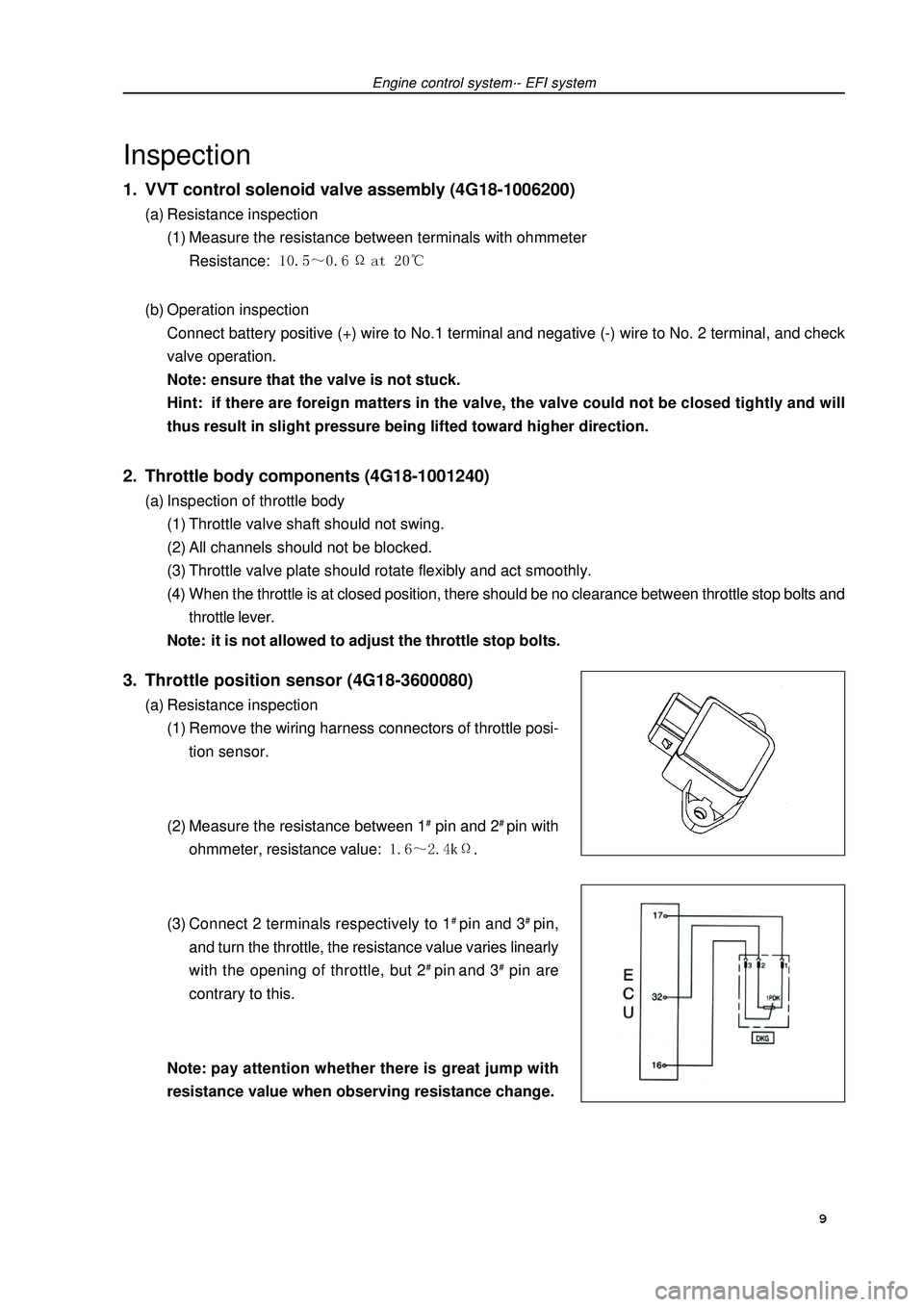
Engine control system·- EFI systemInspection1. VVT control solenoid valve assembly (4G18-1006200)(a) Resistance inspection
(1) Measure the resistance between terminals with ohmmeter
Resistance: (b) Operation inspection
Connect battery positive (+) wire to No.1 terminal and negative (-) wire to No. 2 terminal, and check
valve operation.
Note: ensure that the valve is not stuck.
Hint: if there are foreign matters in the valve, the valve could not be closed tightly and will
thus result in slight pressure being lifted toward higher direction.2. Throttle body components (4G18-1001240)(a) Inspection of throttle body
(1) Throttle valve shaft should not swing.
(2) All channels should not be blocked.
(3) Throttle valve plate should rotate flexibly and act smoothly.
(4) When the throttle is at closed position, there should be no clearance between throttle stop bolts and
throttle lever.
Note: it is not allowed to adjust the throttle stop bolts.3. Throttle position sensor (4G18-3600080)(a) Resistance inspection
(1) Remove the wiring harness connectors of throttle posi-
tion sensor.
(2) Measure the resistance between 1# pin and 2# pin with
ohmmeter, resistance value: .
(3) Connect 2 terminals respectively to 1# pin and 3# pin,
and turn the throttle, the resistance value varies linearly
with the opening of throttle, but 2# pin and 3# pin are
contrary to this.
Note:pay attention whether there is great jump with
resistance value when observing resistance change. 9
Page 32 of 419

Fuel - Fuel tank assemblyFuel tank assembly1. Take measures to prevent gasoline leaking
(see Page 14)
2. Remove rear seat cushion assembly
3. Remove rear floor repairing hole cover
4. Remove No. 2 fuel evaporation assembly
5. Remove fuel tank main fuel hose and oil return pipe
assembly
6. Remove fuel pump assembly
7. Discharge fuel
8. Remove front floor bracket
9. Remove front exhaust pipe assembly(a) Move away carpet and remove oxygen sensor joint.
(b) Remove front exhaust pipe assembly10.Disassemble the vent pipe of fuel hose
11.Disassemble filler pipe from fuel tank
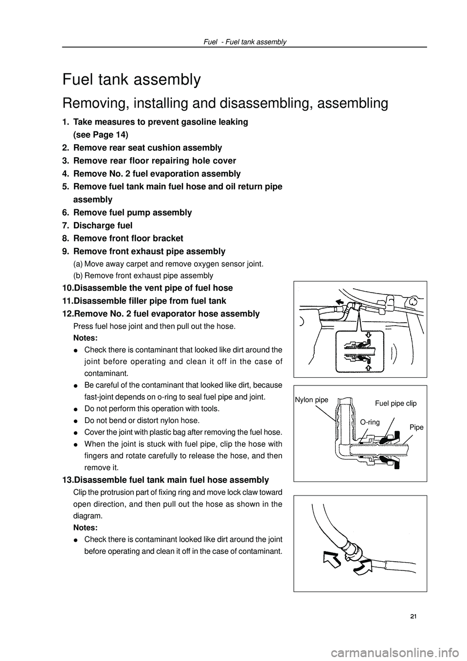
12.Remove No. 2 fuel evaporator hose assemblyPress fuel hose joint and then pull out the hose.
Notes:Check there is contaminant that looked like dirt around the
joint before operating and clean it off in the case of
contaminant.Be careful of the contaminant that looked like dirt, because
fast-joint depends on o-ring to seal fuel pipe and joint.Do not perform this operation with tools.Do not bend or distort nylon hose.Cover the joint with plastic bag after removing the fuel hose.When the joint is stuck with fuel pipe, clip the hose with
fingers and rotate carefully to release the hose, and then
remove it.13.Disassemble fuel tank main fuel hose assemblyClip the protrusion part of fixing ring and move lock claw toward
open direction, and then pull out the hose as shown in the
diagram.
Notes:Check there is contaminant looked like dirt around the joint
before operating and clean it off in the case of contaminant. 21 Removing, installing and disassembling, assemblingFuel pipe clipNylon pipeO-ring
Pipe
Page 46 of 419

Engine mechanism - Valve clearance(4) Turn crankshaft clockwise, and check the sliding
parts are blocked by plunger.
Hint: if the plunger does not eject, press the chain ten-
sion rail toward chain tensioner with screwdriver
or fingers to separate the hook from lock pin and
make the plunger eject.11.Install cylinder head cover components.(a) Install cylinder head cover gasket on cylinder head cover.
(b) Eliminate all old sealant (FIPG) materials.
(c) Coat sealant on 2 positions shown in the diagram.
Notes:Wipe off all the oil stains on junction plane.After coating sealant, finish installation of cylinder head
cover within 3 minutes.After installing, do not refill engine oil within 2 minutes.
(d) Install cylinder head cover components with 9 bolts, 2 seal washers and 2 nuts.
Evenly tighten bolts and nuts at several times.
Torque:
Short bolt: Nut, long bolt etc.: m12. Install drive belt tensioner device.Torque: nut: Bolt: 13. Install fixing bracket absorber on the left of engine.Torque: 14. Check there is oil leakage.Sealant 35 Plunger
TurningPushing
Page 58 of 419

Engine mechanism - Timing chain assembly(2) Use damping pulley bolts to turn crankshaft with its key
toward upward.
(b) Install timing chain on crankshaft timing sprocket and
align the chain link having yellow mark with timing mark
of crankshaft timing sprocket.
Hint: there are 3 yellow chain links on the timing chain.(c) Install crankshaft timing sprocket with special tool.
(d) Install timing chain on camshaft timing sprocket and
align the chain link having yellow mark with camshaft
timing sprocket.27. Install chain guide rail components.Torque: m28. Install chain tension rail components.Torque: 29. Install speed sensor signal panel.Install signal panel with “F” mark toward forward.Toward portSet key
Yellow
mark
Timing mark
Special tool
Color (yellow) mark
Timing mark 47
Page 60 of 419

Engine mechanism - Timing chain assembly(b) Coat engine oil on the chain tensioner, and then install
it.
Torque: Note: when installing the chain temsioner, buckle
on the hook again if plunger has ejected.33. Install damping pulley.(a) Align the key groove on the damping pulley with the
key on the crankshaft, and slide damping pulley in.
(b) Install damping pulley bolts with special tool.
Torque: (c) Turn crankshaft counterclockwise to separate the hook
from lock pin on the plunger.
(d) Turn crankshaft clockwise, and check the chain ten-
sion rail is blocked by plunger.
Hint: if the plunger does not eject, press the chain ten-
sion rail toward chain tensioner with screwdriver
or fingers to separate the hook from lock pin and
make the plunger eject.Special
tool 49 Pushing intoSeparationHook
Pin
TurningPlunger
Pushing
intoTurning
Page 66 of 419

Engine mechanism - Camshaft(4) Ensure whether the timing sprocket of VVT driver
will turn toward timing advance direction in de-
creasing the pressure of timing delay oil duct.
(5) When camshaft timing sprocket turns at max.
timing advance position, release the air pressure
in timing delay side oil duct, and then release the
air in timing advance side oil duct.
Hint: camshaft timing sprocket will turn only af-
ter the lock pin is released.
(d) Check the fixing state of max. delay position.
Ensure camshaft timing sprocket assembly is fixed at
max. delay position.11. Remove VVT driver assembly.(a) Clip the camshaft with a jaw vice, and ensure VVT driver
is locked tightly.
Warning: be careful not to damage camshaft.
(b) As shown in the diagram, seal 5 oil ducts of camshaft
journal with vinyl rubber cloth.
Hint: there are 2 advance side oil ducts in the
groove of camshaft, and clog one of them
with rubber block.
(c) In opposite side of the groove, respectively prick a hole
on vinyl rubber cloth of advance side oil duct surface
and delay side oil duct surface.
(d) Send in 2 oil ducts (advance side oil duct and delay
side oil duct) with the surface rubber cloth pricked
under the pressure of 150Kpa.
Warning:cover the oil ducts with cloth to avoid
oil injecting out in pushing.
(e) Ensure whether the timing sprocket of VVT driver will
turn toward timing advance direction in decreasing the
pressure of timing delay oil duct.
Hint: camshaft timing sprocket will turn toward
advance direction only after the lock pin is
released.
(f) When camshaft timing sprocket turns at max. timing
advance position, release the air pressure in timing
delay side oil duct, and then release the air in timing
advance side oil duct. Warning: if the air pressure in timing advance side oil duct is released earlier than that
in timing delay side oil duct, VVT driver assembly will move suddenly toward
delay side, and the lock pin will be damaged.
(c) Check rotating is smooth.
Besides max. delay position, turn VVT driver assembly within rotating rang and check rotating is
smooth.
Warning: Perform inspection with hands but not with
compressed air.55Delay side
oil ductAdvance
side oil
duct
Close
OpenClose
Open
Vinyl rubber cloth
Rubber block
Delay side
oil ductAdvance
side oil
ductDropping
pressure
Maintaining
pressure Delay side
oil ductAdvance
side oil
duct
Dropping
pressure
Maintaining
pressure Delay side
oil ductAdvance
side oil
duct