Page 16 of 419
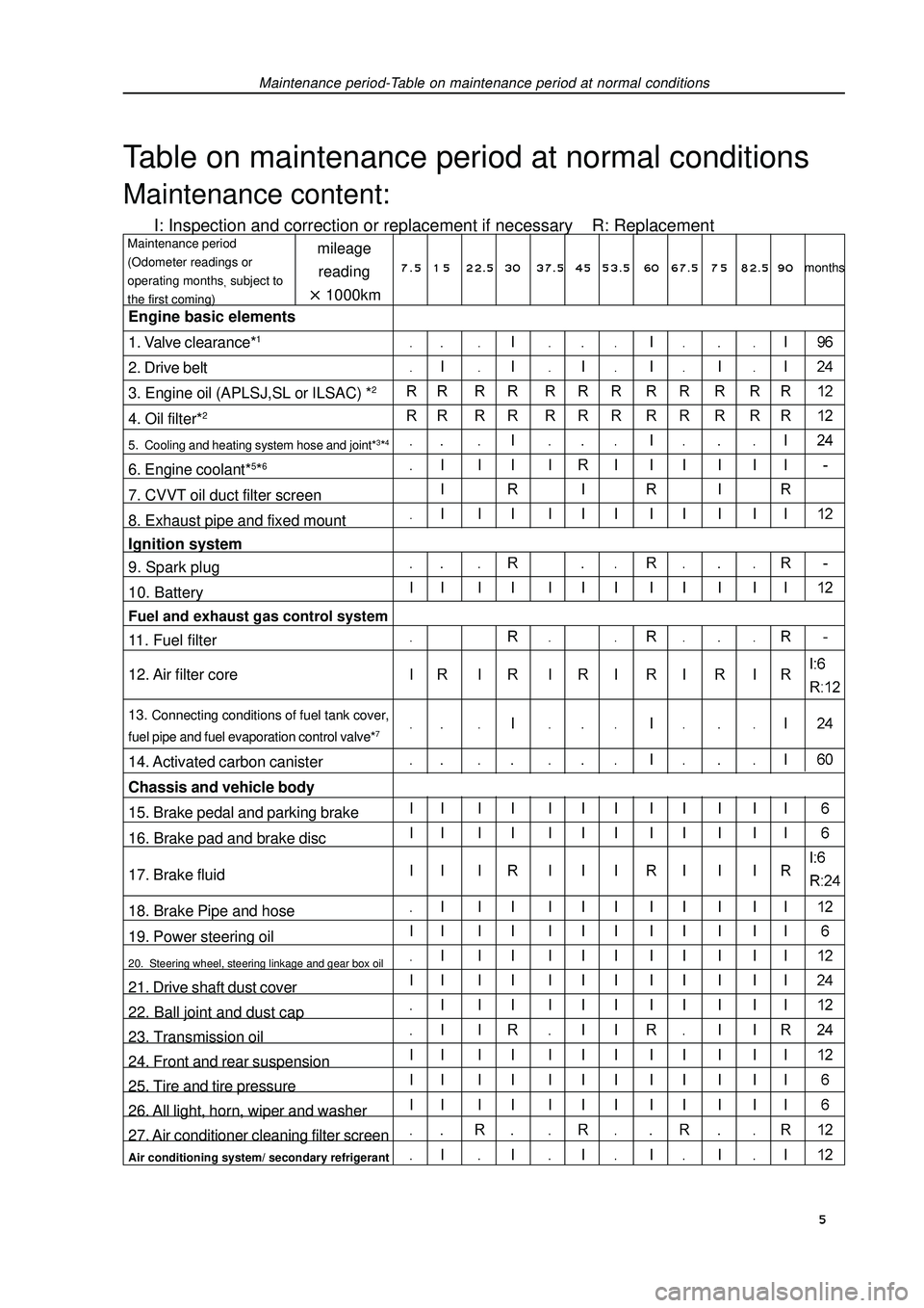
Maintenance period-Table on maintenance period at normal conditionsTable on maintenance period at normal conditionsMaintenance content:I: Inspection and correction or replacement if necessary R: Replacementmileage
reading1000kmMaintenance period
(Odometer readings or
operating monthssubject to
the first coming)Engine basic elements
1. Valve clearance*12. Drive belt
3. Engine oil (APLSJ,SL or ILSAC) *24. Oil filter*25. Cooling and heating system hose and joint*3*46. Engine coolant*5*67. CVVT oil duct filter screen
8. Exhaust pipe and fixed mount
Ignition system
9. Spark plug
10. BatteryFuel and exhaust gas control system11. Fuel filter
12. Air filter core13. Connecting conditions of fuel tank cover,
fuel pipe and fuel evaporation control valve*714. Activated carbon canister
Chassis and vehicle body
15. Brake pedal and parking brake
16. Brake pad and brake disc
17. Brake fluid
18. Brake Pipe and hose
19. Power steering oil20. Steering wheel, steering linkage and gear box oil21. Drive shaft dust cover
22. Ball joint and dust cap
23. Transmission oil
24. Front and rear suspension
25. Tire and tire pressure
26. All light, horn, wiper and washer
27. Air conditioner cleaning filter screenAir conditioning system/ secondary refrigerant7 . 5 1 5 22.5 3037.5 4553.5 60 67.5 7 582.5 90months 5
Page 17 of 419
Note: *1 Indicating that check valve noise and engine vibration condition, and adjust them if necessary.*2 It is suggested that see operating modes on page 116 of operating instruction to perform.*3 Indicating that check once every 20000km or 12 moths after 80000km or 48 months.*4 Indicating that check water tank and condenser are blocked by leaves, dust or insects, and clean
hose connections.*5 Replace at initial 60000km, and replace every 30000km in future.*6 Only “Geely genuine ultra-long engine coolant” or equivalent high-quality ethylene glycol engine
coolant without silicate, amines, nitrite, borate and with long-life compound organic acid technology
are allowed to use, and coolant should be repeated several times until it is filled up.*7 Indicating that check once every 20000km or 12 moths after 80000km or 48 months.Maintenance period-Table on maintenance period at normal conditions 6
Page 24 of 419
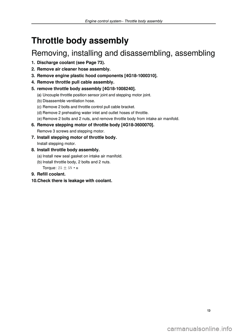
Engine control system·- Throttle body assemblyThrottle body assemblyRemoving, installing and disassembling, assembling1. Discharge coolant (see Page 73).
2. Remove air cleaner hose assembly.
3. Remove engine plastic hood components [4G18-1000310].
4. Remove throttle pull cable assembly.
5. remove throttle body assembly [4G18-1008240].(a) Uncouple throttle position sensor joint and stepping motor joint.
(b) Disassemble ventilation hose.
(c) Remove 2 bolts and throttle control pull cable bracket.
(d) Remove 2 preheating water inlet and outlet hoses of throttle.
(e) Remove 2 bolts and 2 nuts, and remove throttle body from intake air manifold.6. Remove stepping motor of throttle body [4G18-3600070].Remove 3 screws and stepping motor.7. Install stepping motor of throttle body.Install stepping motor.8. Install throttle body assembly.(a) Install new seal gasket on intake air manifold.
(b) Install throttle body, 2 bolts and 2 nuts.
Torque: 9. Refill coolant.
10.Check there is leakage with coolant.
13
Page 37 of 419
![GEELY FC 2008 Workshop Manual Engine mechanismEngine assemblyInspection1. Check coolant.
2. Check engine oil.
3. Check battery.
4. Check air filter assembly.
5. Check spark plug [4G18-3705113].
6. Check drive belt [4G18-1307107].H GEELY FC 2008 Workshop Manual Engine mechanismEngine assemblyInspection1. Check coolant.
2. Check engine oil.
3. Check battery.
4. Check air filter assembly.
5. Check spark plug [4G18-3705113].
6. Check drive belt [4G18-1307107].H](/manual-img/58/57161/w960_57161-36.png)
Engine mechanismEngine assemblyInspection1. Check coolant.
2. Check engine oil.
3. Check battery.
4. Check air filter assembly.
5. Check spark plug [4G18-3705113].
6. Check drive belt [4G18-1307107].Hint: do not check belt tension, because automatic tensioner is applied.7. Check ignition timing.(a) Warm up engine.
(b) Connect timing lamp to engine.
(c) Check ignition timing at idle speed.
Ignition timing: before top dead center Note: when checking ignition timing, place
transmission at neutral position.
Hint: After run the engine for 5 seconds with rotating
speed of 1000-1300rpm, check the engine could
recover to idle running.8. Check engine idle speed.(a) Warm up engine and run it at idle speed.
(b) Read engine rotating number in data flow with diagnostic instrument.
(c) Check idle speed.
Idle speed: about 750-850rpm
Notes:When checking idle speed, place cooling fan at OFF position.Turn off all auxiliary devices and air conditioner.Engine mechanism - Engine assemblyK-line 26
Page 47 of 419
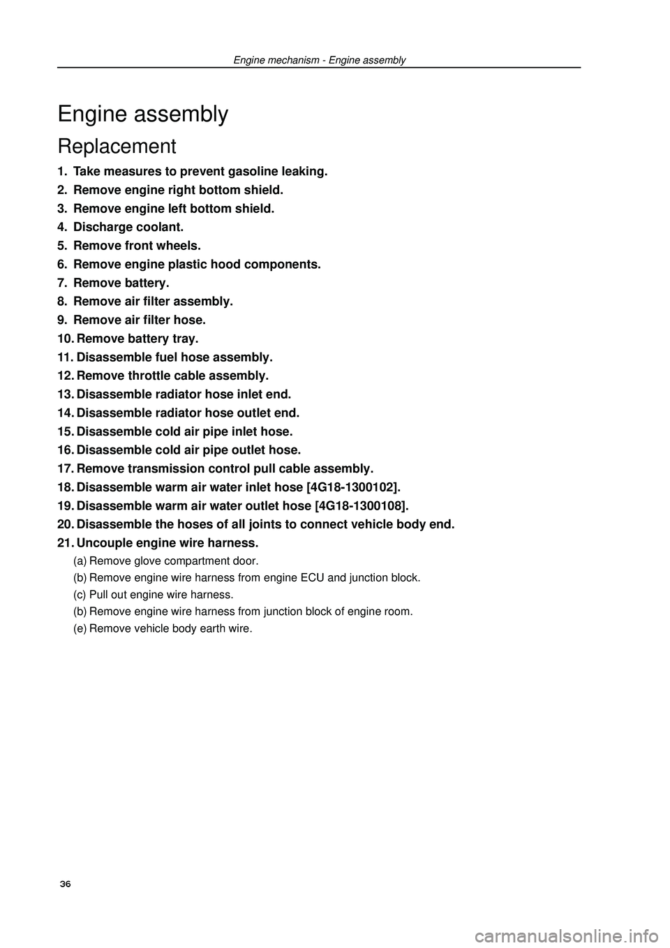
Engine mechanism - Engine assemblyEngine assemblyReplacement1. Take measures to prevent gasoline leaking.
2. Remove engine right bottom shield.
3. Remove engine left bottom shield.
4. Discharge coolant.
5. Remove front wheels.
6. Remove engine plastic hood components.
7. Remove battery.
8. Remove air filter assembly.
9. Remove air filter hose.
10. Remove battery tray.
11. Disassemble fuel hose assembly.
12. Remove throttle cable assembly.
13. Disassemble radiator hose inlet end.
14. Disassemble radiator hose outlet end.
15. Disassemble cold air pipe inlet hose.
16. Disassemble cold air pipe outlet hose.
17. Remove transmission control pull cable assembly.
18. Disassemble warm air water inlet hose [4G18-1300102].
19. Disassemble warm air water outlet hose [4G18-1300108].
20. Disassemble the hoses of all joints to connect vehicle body end.
21. Uncouple engine wire harness.(a) Remove glove compartment door.
(b) Remove engine wire harness from engine ECU and junction block.
(c) Pull out engine wire harness.
(b) Remove engine wire harness from junction block of engine room.
(e) Remove vehicle body earth wire. 36
Page 55 of 419
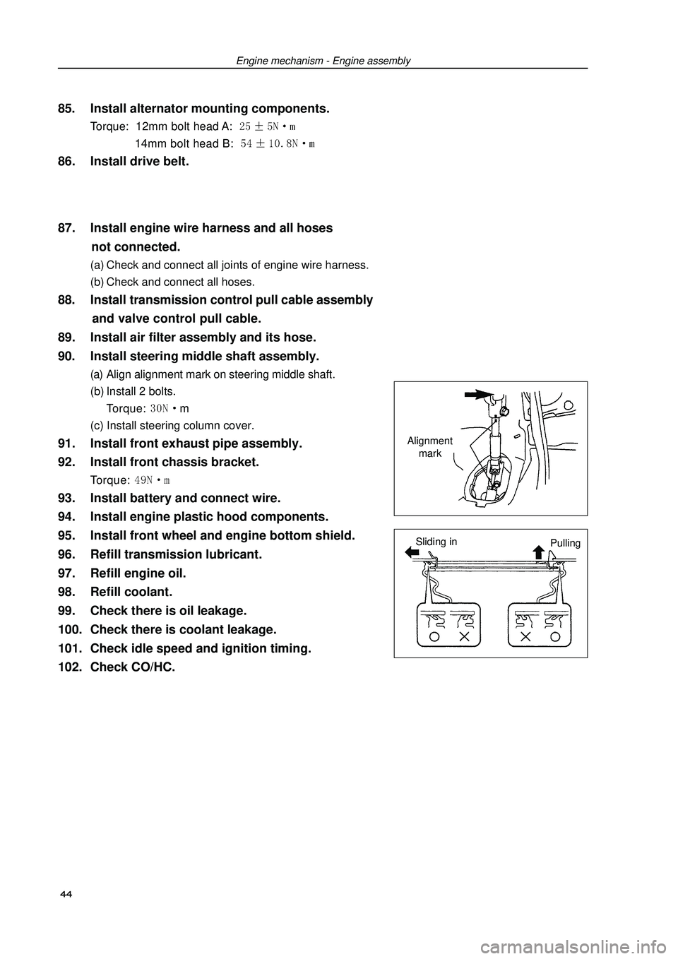
Engine mechanism - Engine assembly85. Install alternator mounting components.Torque: 12mm bolt head A: 14mm bolt head B: 86. Install drive belt.
87. Install engine wire harness and all hoses
not connected.(a) Check and connect all joints of engine wire harness.
(b) Check and connect all hoses.88. Install transmission control pull cable assembly
and valve control pull cable.
89. Install air filter assembly and its hose.
90. Install steering middle shaft assembly.(a) Align alignment mark on steering middle shaft.
(b) Install 2 bolts.
Torque: m
(c) Install steering column cover.91. Install front exhaust pipe assembly.
92. Install front chassis bracket.Torque: 93. Install battery and connect wire.
94. Install engine plastic hood components.
95. Install front wheel and engine bottom shield.
96. Refill transmission lubricant.
97. Refill engine oil.
98. Refill coolant.
99. Check there is oil leakage.
100. Check there is coolant leakage.
101. Check idle speed and ignition timing.
102. Check CO/HC.Alignment
mark
Sliding in
Pulling 44
Page 56 of 419
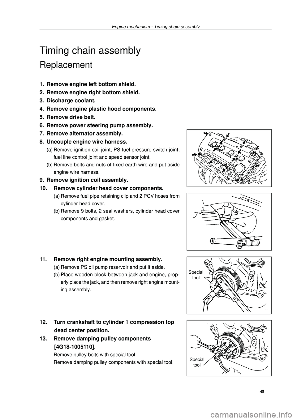
Engine mechanism - Timing chain assemblyTiming chain assemblyReplacement1. Remove engine left bottom shield.
2. Remove engine right bottom shield.
3. Discharge coolant.
4. Remove engine plastic hood components.
5. Remove drive belt.
6. Remove power steering pump assembly.
7. Remove alternator assembly.
8. Uncouple engine wire harness.(a) Remove ignition coil joint, PS fuel pressure switch joint,
fuel line control joint and speed sensor joint.
(b) Remove bolts and nuts of fixed earth wire and put aside
engine wire harness.9. Remove ignition coil assembly.
10. Remove cylinder head cover components.(a) Remove fuel pipe retaining clip and 2 PCV hoses from
cylinder head cover.
(b) Remove 9 bolts, 2 seal washers, cylinder head cover
components and gasket.11. Remove right engine mounting assembly.(a) Remove PS oil pump reservoir and put it aside.
(b) Place wooden block between jack and engine, prop-
erly place the jack, and then remove right engine mount-
ing assembly.12. Turn crankshaft to cylinder 1 compression top
dead center position.
13. Remove damping pulley components
[4G18-1005110].Remove pulley bolts with special tool.
Remove damping pulley components with special tool.Special
tool
Special
tool45
Page 62 of 419
Engine mechanism - Timing chain assembly41. Install alternator mounting components.Torque: 12mm bolt head: 14mm bolt head: m42. Refill coolant.
43. Check there is coolant leakage.
44. Check there is oil leakage.
51