2008 GEELY FC oil change
[x] Cancel search: oil changePage 7 of 419

Replacement...................................................
72
Coolant.................................................................
73
Replacement...................................................
73
Lubrication
Lubricating system...............................................
74
On-vehicle inspection......................................
74
Oil filter assembly.................................................
75
Replacement....................................................
75
Oil pump assembly...............................................
76
Replacement....................................................
76
Ignition
Ignition system.....................................................
77
Inspection........................................................
77
On-vehicle inspection......................................
77
Starting and charging
Starting system.....................................................
79
Inspection........................................................
79
Charging system..................................................
81
Precautions......................................................
81
On-vehicle inspection......................................
82
Alternator components..............................................
84
Replacement....................................................
84
Starter components..............................................
85
Replacement....................................................
85
Front suspension
Front suspension system....................................
86
Table on trouble occurrence...........................
86
Front wheel alignment.........................................
87
Adjustment......................................................
87
Front absorber and helical spring.......................
90
Overhaul..........................................................
90
Handling..........................................................
93
Lower left control arm assembly.........................
94
Replacement...................................................
94Front stabilizer bar...............................................
96
Overhaul..........................................................
96
Front left lower control arm ball joint assembly
..
99
Replacement...................................................
99
Rear suspension
Rear suspension system....................................
100
Table on trouble occurrence..........................
100
Rear wheel alignment.........................................
101
Adjustment.....................................................
101
Rear strut assembly...........................................
102
Overhaul........................................................
102
Handling.........................................................
104
Rear stabilizer bar..............................................
105
Overhaul........................................................
105
Rear shaft assembly...........................................
106
Overhaul........................................................
106
Tire and wheel
Wheel and tire system.......................................
109
Inspection......................................................
109
Drive shaft
Drive shaft.......................................................
111
Notes.............................................................
111
Malfunction phenomenon table....................
111
Inspection on automobile.............................
11 2
Front drive shaft.................................................
11 3
Overhaul........................................................
11 3
Left front shaft hub assembly............................
123
Change..........................................................
123
Left front shaft hub bolt......................................
128
Change..........................................................
128
Left rear shaft hub and bearing assembly........
129
Change..........................................................
129
Left rear shaft hub bolt.......................................
131
Change..........................................................
131
Page 8 of 419

Brake
Brake system......................................................
132
Notes..............................................................
132
Remove malfunction...........................................
133
Malfunction phenomenon table.....................
133
Brake liquid.........................................................
135
Discharge the air in brake system.................
135
Brake pedal assembly........................................
136
Adjustment.....................................................
136
Change..........................................................
137
Vacuum booster assembly.................................
138
Inspection on automobile...............................
138
Change..........................................................
138
Front brake assembly.........................................
141
Overhaul........................................................
141
Rear brake assembly.........................................
144
Overhaul........................................................
144Hydraulic pressure control unit (equipping with ABS)...148
Inspection on automobile...............................
148
Change..........................................................
148
Speed sensor of front wheel..............................
151
Change..........................................................
151
Speed sensor of rear wheels...........................
152
Change..........................................................
152
Parking brake
Parking brake system.........................................
154
Malfunction phenomenon table.....................
154
Adjustment.....................................................
154
Parking brake handle assembly.........................
155
Change..........................................................
155
Parking front bake pull cable assembly............
156
Change..........................................................
156
Parking rear brake pull cable assembly...........
158
Change..........................................................
158
Parking brake assembly....................................
161
Overhaul........................................................
161Transmission
Disassemble assembly...................................
165
Assemble the assembly....................................
191
Steering column
Steering system..................................................
192
Note...............................................................
192
Malfunction phenomenon table.....................
192
Inspection on automobile...............................
193
Steering column system.....................................
194
Overhaul........................................................
194
Power steering
Power steering system......................................
198
Note...............................................................
198
Malfunction phenomenon table....................
199
Inspection on automobile.............................
200
Power steering oil pump assembly..................
203
Overhaul........................................................
203
Power steering gear assembly.........................
205
Overhaul........................................................
205
Air conditioner
Air conditioning system......................................
213
Note...............................................................
213
Inspection on automobile...............................
213
Inspection......................................................
214
Refrigerant..........................................................
215
Inspection on automobile...............................
215
Change..........................................................
221
Refrigerant pipeline............................................
222
Parts...............................................................
222Control assembly, air conditioner control panel (AUTO A/C)...223
Overhaul........................................................
223
Fan assembly...................................................
224
Overhaul........................................................
224
Air conditioner central heating core assembly..
227
Overhaul........................................................
227
Compressor assembly.....................................
234
Page 19 of 419

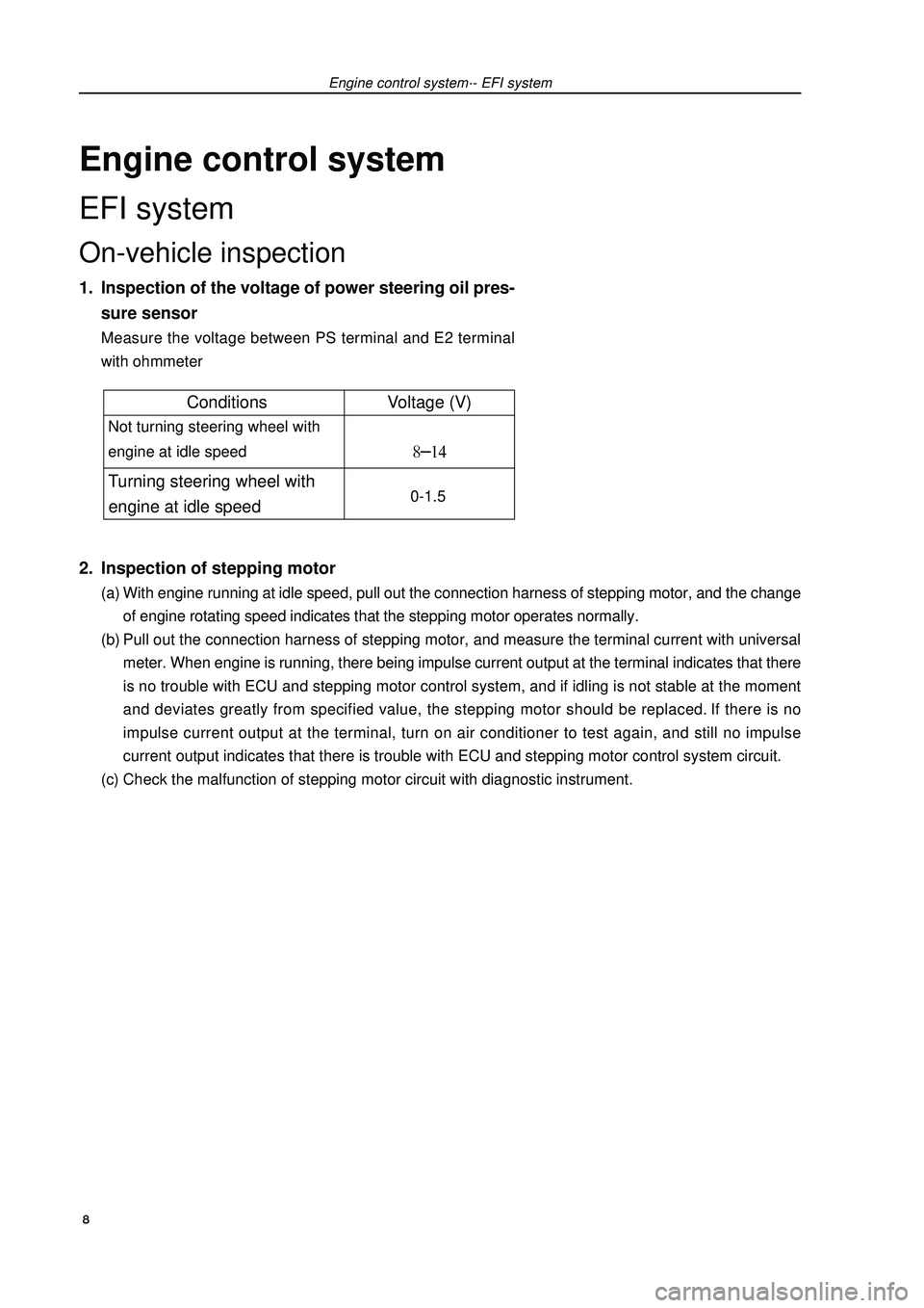
Engine control systemEFI systemOn-vehicle inspection1. Inspection of the voltage of power steering oil pres-
sure sensorMeasure the voltage between PS terminal and E2 terminal
with ohmmeter2. Inspection of stepping motor(a) With engine running at idle speed, pull out the connection harness of stepping motor, and the change
of engine rotating speed indicates that the stepping motor operates normally.
(b) Pull out the connection harness of stepping motor, and measure the terminal current with universal
meter. When engine is running, there being impulse current output at the terminal indicates that there
is no trouble with ECU and stepping motor control system, and if idling is not stable at the moment
and deviates greatly from specified value, the stepping motor should be replaced. If there is no
impulse current output at the terminal, turn on air conditioner to test again, and still no impulse
current output indicates that there is trouble with ECU and stepping motor control system circuit.
(c) Check the malfunction of stepping motor circuit with diagnostic instrument.Engine control system·- EFI system 8Conditions Voltage (V) Not turning steering wheel with
engine at idle speed Turning steering wheel with
engine at idle speed 0-1.5
Page 34 of 419

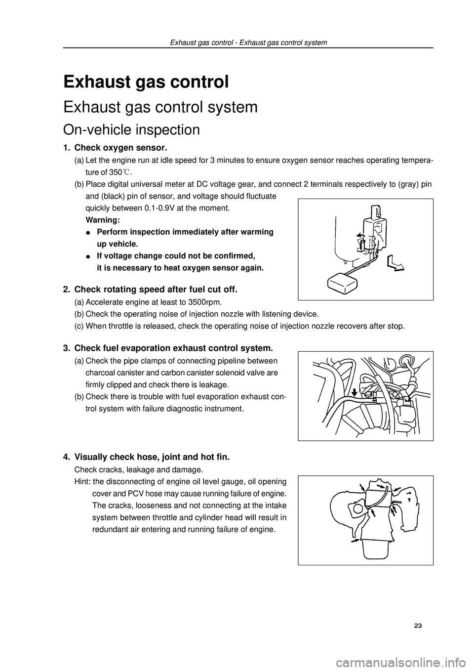
Exhaust gas controlExhaust gas control systemOn-vehicle inspection1. Check oxygen sensor.(a) Let the engine run at idle speed for 3 minutes to ensure oxygen sensor reaches operating tempera-
ture of 350(b) Place digital universal meter at DC voltage gear, and connect 2 terminals respectively to (gray) pin
and (black) pin of sensor, and voltage should fluctuate
quickly between 0.1-0.9V at the moment.
Warning:Perform inspection immediately after warming
up vehicle.If voltage change could not be confirmed,
it is necessary to heat oxygen sensor again.Exhaust gas control - Exhaust gas control system2. Check rotating speed after fuel cut off.(a) Accelerate engine at least to 3500rpm.
(b) Check the operating noise of injection nozzle with listening device.
(c) When throttle is released, check the operating noise of injection nozzle recovers after stop.3. Check fuel evaporation exhaust control system.(a) Check the pipe clamps of connecting pipeline between
charcoal canister and carbon canister solenoid valve are
firmly clipped and check there is leakage.
(b) Check there is trouble with fuel evaporation exhaust con-
trol system with failure diagnostic instrument.4. Visually check hose, joint and hot fin.Check cracks, leakage and damage.
Hint: the disconnecting of engine oil level gauge, oil opening
cover and PCV hose may cause running failure of engine.
The cracks, looseness and not connecting at the intake
system between throttle and cylinder head will result in
redundant air entering and running failure of engine.23
Page 41 of 419
![GEELY FC 2008 Workshop Manual Engine mechanism - Valve clearanceValve clearanceAdjustment1. Remove engine plastic hood components.
2. Remove ignition coil components [4G18-3705110].
3. Remove cylinder head cover components [4G18-
GEELY FC 2008 Workshop Manual Engine mechanism - Valve clearanceValve clearanceAdjustment1. Remove engine plastic hood components.
2. Remove ignition coil components [4G18-3705110].
3. Remove cylinder head cover components [4G18-](/manual-img/58/57161/w960_57161-40.png)
Engine mechanism - Valve clearanceValve clearanceAdjustment1. Remove engine plastic hood components.
2. Remove ignition coil components [4G18-3705110].
3. Remove cylinder head cover components [4G18-
1003130].
4. Remove engine right bottom shield.
5. Turn crankshaft to cylinder 1 compression top dead
center position.(a) Turn crankshaft pulley to align its groove with “o” mark on
timing chain hood.
(b) Check dot marks on camshaft timing sprocket and VVT
timing sprocket, and they should be in a line on timing chain
hood surface as shown in the diagram.
Hint: if not, turn crankshaft for one circle again
and align the above marks.6. Check valve clearance.(a) Only check the valves shown in the diagram.
(1) Measure the clearance between valve tappet and cam-
shaft with plug gauge.
(2) Record valve clearance measuring value exceeding
specification, and this value will be used to determine
valve tappet thickness that needs change.
Valve clearance (cold vehicle)Intake airExhaust(b) Turn crankshaft for one circle ), and cylinder 4 is
turned to compression top dead center position.
(c) Only check the valves shown in the diagram. Measure valve
clearance (see step (a)).7. Remove drive beltSlowly turn drive belt tensioner clockwise to loosen it.
Then remove drive belt and put back drive belt tensioner slowly
and gently. 30 Mark
Mark
Mark
Timing chain
hood surface
Groove
Page 85 of 419

LubricationLubricating systemOn-vehicle inspection1. Check oil level.During engine warming up and after it flames out for 5 minutes, check oil level, and the level should
be between two marks on oil dipstick at the moment.If oil level is too low, check there is leakage, and
refill oil up to upper mark on oil dipstick.
Note: oil level should not be above upper mark on oil
dipstick.2. Check oil quality.(a) Check there is deterioration, water penetration, color
change or thinning with oil.
(b) If oil quality becomes poor, please replace with new oil.
Hint: oil grades: API, SH, SJ, SG grade oil or ILSAC
multigrade oil. Recommended viscosity is
shown as below.
The temperature increases from left to right.3. Remove oil pressure alerter assembly.(a) Uncouple oil pressure alerter joint.
(b) Install oil pressure alerter with special tool.4. Install oil pressure gauge.Install oil pressure gauge.5. Warm up vehicle.
6. Check oil pressure.Oil pressure:7. Install oil pressure alerter.(a) Coat adhesive on 2nd or 3rd circle thread of oil pressure
alerter.
Adhesive: anaerobic pipe thread sealing adhesive
1545 (Kesaixin 1545).
(b) Install oil pressure alerter with special tool.
Torque: m
(c) Connect oil pressure alerter joint.8. Start engine and check there is leakage.Lubrication - lubricating systemRecommended viscosity (SAE)
Oil pressure alerter
Oil pressure gauge
Adhesive74Temperature range in forecasting next
oil replacement
Page 124 of 419

Drive shaft--Front drive shaftFront drive shaftOverhaulHint: overhaul procedure for right side is same as the left
side.1. Check the drive shaft (referring to page 111).
2. Discharge the oil in gearbox.(a) Disassemble oil plug and gasket to discharge the oil in
gearbox.
(b) Change with a new gasket and assemble oil discharging
plug.
Torque: 45
± ±± ±
± 5 N·m3. Disassemble front wheels.
4. Disassemble fixing nut of drive shaft [64000083](a) Use special tool and hammer to unclench the concave part
of fixing nut.
(b) Disassemble the fixing nut.5. Disassemble speed sensor assembly of left front
wheels (equipping with ABS) [67000020](a) Disassemble the bolt, and disassemble sensor wiring har-
ness and brake hose from the absorber.
(b) Disassemble the bolt, and disassemble speed sensor from
steering knuckle.special
tool113
Page 144 of 419

Brake--Remove malfunctionRemove malfunctionMalfunction phenomenon tableUse following table to help you find the reason of malfunction, the number in table indicates the preferred
sequence of possible reasons of malfunction. Please check every part by sequence, if necessary, change
this part.Malfunction phenomenon Possible malfunction part Reference page
1. Brake system (leaking oil). -
The height of brake pedal is too 2. Brake system (entering air). 135
low or brake pedal is loose. 3. Piston oil seal (abraded or damaged). 141, 144
4. Brake main pump (invalid) 138
5. Vacuum booster lever (adjusted badly) 138
1. Brake pedal free travel (too small). 136
2. Parking brake handle travel (adjusted badly). 154
3. Parking brake pull cable (lag). 156, 158
4. Brake block (damaged or distorted). 141, 144
Brake lag 5. Piston (locked). 141, 144
6. Piston (freezed).141, 144
7. Tensility or return spring (invalid). 161
8. Vacuum booster lever (adjusted badly). 138
9. Vacuum boosting system (vacuum leakage). 138
10. Brake main pump (invalid). 138
1. Piston (locked). 141, 144
2. Brake block (oil dirt).141, 144
Brake offset 3. Piston (freezed).141, 144
4. Brake disk (scratched). 141, 144
5. Brake block (abraded or distorted).141, 144
1. Brake system (leaking oil).
2. Brake system (entering air). 135
3. Brake block (abraded). 141, 144
4. Brake block (damaged or distorted). 141, 144Brake pedal is too hard to make power lack.5. Brake block (oil dirt).141, 144
6. Brake block (sclerosesed). 141, 144
7. Brake disk (scratched). 141, 144
8. Vacuum booster lever (adjusted badly). 138
9. Vacuum boosting system (vacuum leakage). 138133