Page 300 of 3000
SE–8SEAT – FRONT POWER SEAT CONTROL SYSTEM
SE
Main body ECUPower seat control switch and
ECU• Driver side door courtesy light
switch signal
• Key unlock warning switch
signal
• Ignition switch signalBEAN Transmitting ECU
(Transmitter)Receiving ECU Signals Communication method
Page 304 of 3000
SEAT – REAR NO. 2 SEAT ASSEMBLY (for Power Seat Type LH Side)SE–101
SE
7. REMOVE NO. 2 SEATBACK COVER SUB-ASSEMBLY
WITH PAD
(a) Disconnect the connectors.
(b) Disengage the 3 clamps and remove the No. 2
seatback cover sub-assembly with pad.
8. REMOVE NO. 2 SEATBACK COVER SUB-ASSEMBLY
(a) Remove the 10 hog rings and No. 2 seatback cover
sub-assembly.
9. REMOVE NO. 2 SEATBACK PAD
10. REMOVE FOLD SEAT CONTROL ECU
(a) Remove the 2 nuts and fold seat control ECU.
11. REMOVE NO. 2 SEATBACK FRAME SUB-ASSEMBLY
(a) Remove the 4 bolts and No. 2 seatback frame sub-
assembly.
B126848E01
B126849E01
B126850
B126851
Page 312 of 3000

ENGINE HOOD / DOOR – POWER SLIDE DOOR SYSTEMED–5
ED
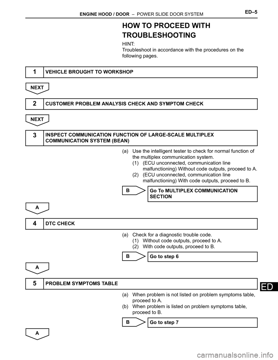
HOW TO PROCEED WITH
TROUBLESHOOTING
HINT:
Troubleshoot in accordance with the procedures on the
following pages.
NEXT
NEXT
(a) Use the intelligent tester to check for normal function of
the multiplex communication system.
(1) (ECU unconnected, communication line
malfunctioning) Without code outputs, proceed to A.
(2) (ECU unconnected, communication line
malfunctioning) With code outputs, proceed to B.
B
A
(a) Check for a diagnostic trouble code.
(1) Without code outputs, proceed to A.
(2) With code outputs, proceed to B.
B
A
(a) When problem is not listed on problem symptoms table,
proceed to A.
(b) When problem is listed on problem symptoms table,
proceed to B.
B
A
1VEHICLE BROUGHT TO WORKSHOP
2CUSTOMER PROBLEM ANALYSIS CHECK AND SYMPTOM CHECK
3INSPECT COMMUNICATION FUNCTION OF LARGE-SCALE MULTIPLEX
COMMUNICATION SYSTEM (BEAN)
Go To MULTIPLEX COMMUNICATION
SECTION
4DTC CHECK
Go to step 6
5PROBLEM SYMPTOMS TABLE
Go to step 7
Page 313 of 3000
ED–6ENGINE HOOD / DOOR – POWER SLIDE DOOR SYSTEM
ED
(a) Data List / Active Test (See page ED-22).
(b) Operation check (See page ED-6).
(c) Inspection.
(d) Terminals of ECU (See page ED-17).
NEXT
NEXT
NEXT
NEXT
6PERFORM TROUBLESHOOTING ACCORDING TO MALFUNCTION SYMPTOM
7ADJUST, REPAIR OR REPLACE
8RESET POWER SLIDE DOOR SYSTEM
9CONFIRMATION TEST
END
Page 324 of 3000
ES–2562GR-FE ENGINE CONTROL SYSTEM – SFI SYSTEM
ES
(a) Replace the VVT sensor (See page ES-509).
NEXT
(a) Connect the intelligent tester to the DLC3.
(b) Turn the ignition switch to the ON position.
(c) Turn the intelligent tester on.
(d) Clear the DTCs.
(e) Select the following menu items: DIAGNOSIS /
ENHANCED OBD II / DTC / INFO / PENDING CODES.
(f) Read the DTCs.
Result
HINT:
If the engine does not start, replace the ECM.
B
A
5REPLACE VVT SENSOR (FOR EXHAUST CAMSHAFT)
6CHECK WHETHER DTC OUTPUT RECURS
Display (DTC Output) Proceed to
No output A
P0365, P0352, P0353, P0354, P0355 or P0356 B
REPLACE ECM (See page ES-498)
END
Page 354 of 3000

ES–282GR-FE ENGINE CONTROL SYSTEM – SFI SYSTEM
ES
• Vehicle was driven in the city area (or on free-
way) for 10 minutes or more.
(b) Monitor Conditions
(1) Turn the ignition switch off and wait for 6 hours.
HINT:
Do not start the engine until checking Readiness
Monitor status. If the engine is started, the step
described above must be repeated.
(c) Monitor Status
(1) Connect an intelligent tester to the DLC3.
(2) Turn the ignition switch to the ON position.
(3) Turn the tester or scan tool ON.
(4) Check the Readiness Monitor status displayed
on the tester or scan tool.
If the status does not switch to COMPL
(complete), restart the engine, make sure that
the preconditions have been met, and then
perform the Monitor Conditions again.
4. A/F SENSOR AND HO2S MONITORS
(a) Preconditions
The monitor will not run unless:
• 2 minutes or more have elapsed since the engine
was started.
• The Engine Coolant Temperature (ECT) is 75
C
(167
F) or more.
• Cumulative driving time at a vehicle speed of 30
mph (48 km/h) or more exceeds 6 minutes.
• Air-fuel ratio feedback control is performed.
• Fuel-cut control is performed for 8 seconds or
more (for the Rear HO2 Sensor Monitor).
(b) Drive Pattern for front A/F sensor and HO2 sensor.
(1) Connect an intelligent tester to the DLC3.
(2) Turn the ignition switch to the ON position.
(3) Turn the tester ON.
(4) Clear the DTCs.
(5) Start the engine, and warm it up until the ECT
reaches 75
C (167F) or higher.
(6) Drive the vehicle at 38 mph (60 km/h) or more
for at least 10 minutes.
(7) Change the transmission to the 2nd gear.
(8) Accelerate the vehicle to 40 mph (64 km/h) or
more by depressing the accelerator pedal for at
least 10 seconds (Procedure "A").
(9) Soon after performing procedure "A" above,
release the accelerator pedal for at least 4
seconds without depressing the brake pedal, in
order to execute fuel-cut control (Procedure "B").
(10) Allow the vehicle to decelerate until the vehicle
speed declines to less than 6 mph (10 km/h)
(Procedure "C").
(11) Repeat procedures from "A" through "C" above
at least 3 times in one driving cycle.
Page 359 of 3000

2GR-FE ENGINE CONTROL SYSTEM – SFI SYSTEMES–41
ES
DIAGNOSIS SYSTEM
1. DESCRIPTION
(a) When troubleshooting OBD II (On-Board
Diagnostics) vehicles, an intelligent tester
(complying with SAE J1987) must be connected to
the DLC3 (Data Link Connector 3) of the vehicle.
Various data in the vehicle's ECM (Engine Control
Module) can be then read.
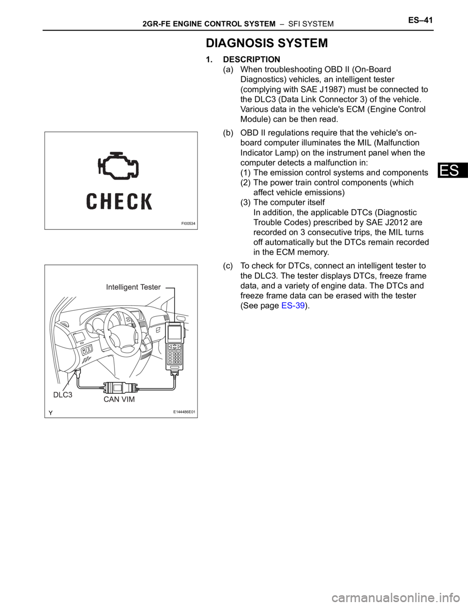
(b) OBD II regulations require that the vehicle's on-
board computer illuminates the MIL (Malfunction
Indicator Lamp) on the instrument panel when the
computer detects a malfunction in:
(1) The emission control systems and components
(2) The power train control components (which
affect vehicle emissions)
(3) The computer itself
In addition, the applicable DTCs (Diagnostic
Trouble Codes) prescribed by SAE J2012 are
recorded on 3 consecutive trips, the MIL turns
off automatically but the DTCs remain recorded
in the ECM memory.
(c) To check for DTCs, connect an intelligent tester to
the DLC3. The tester displays DTCs, freeze frame
data, and a variety of engine data. The DTCs and
freeze frame data can be erased with the tester
(See page ES-39).
FI00534
E144486E01
Page 363 of 3000

2GR-FE ENGINE CONTROL SYSTEM – SFI SYSTEMES–45
ES
DTC CHECK / CLEAR
NOTICE:
All the stored DTCs and freeze frame data are erased if:
1) the ECM is changed from normal mode to check mode
or vice versa; or 2) the ignition switch is turned from ON
to ACC or off while in check mode.
Before changing modes, always check and make a note
of any DTCs and freeze frame data.
HINT:
• DTCs which are stored in the ECM can be displayed on an
intelligent tester. An intelligent tester can display current
and pending DTCs.
• Some DTCs are not set if the ECM does not detect the
same malfunction again during the second consecutive
driving cycle. However, such malfunctions, detected on
only one occasion, are stored as pending DTCs.
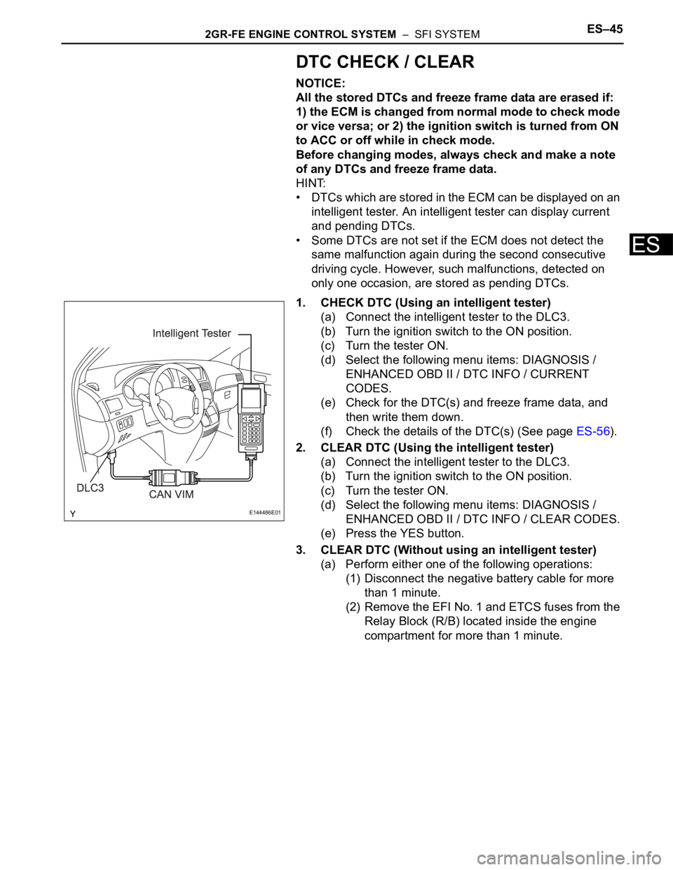
1. CHECK DTC (Using an intelligent tester)
(a) Connect the intelligent tester to the DLC3.
(b) Turn the ignition switch to the ON position.
(c) Turn the tester ON.
(d) Select the following menu items: DIAGNOSIS /
ENHANCED OBD II / DTC INFO / CURRENT
CODES.
(e) Check for the DTC(s) and freeze frame data, and
then write them down.
(f) Check the details of the DTC(s) (See page ES-56).
2. CLEAR DTC (Using the intelligent tester)
(a) Connect the intelligent tester to the DLC3.
(b) Turn the ignition switch to the ON position.
(c) Turn the tester ON.
(d) Select the following menu items: DIAGNOSIS /
ENHANCED OBD II / DTC INFO / CLEAR CODES.
(e) Press the YES button.
3. CLEAR DTC (Without using an intelligent tester)
(a) Perform either one of the following operations:
(1) Disconnect the negative battery cable for more
than 1 minute.
(2) Remove the EFI No. 1 and ETCS fuses from the
Relay Block (R/B) located inside the engine
compartment for more than 1 minute.
E144486E01