Page 82 of 3000

IG–82GR-FE IGNITION – IGNITION COIL AND SPARK PLUG
IG
(2) Remove the spark plugs.
(3) Visually check the spark plug.
If the electrode is dry, the spark plug is
functioning properly. If the electrode is damp,
proceed to the next step.
(c) Check the spark plug for any damage to its threads
and insulator. If there is damage, replace the spark
plug.
Recommended spark plug
NOTICE:
Use only the listed spark plug or equivalent to
ensure engine performance and smooth
driveability.
(d) Check the spark plug electrode gap.
Maximum electrode gap for used spark plug:
1.4 mm (0.055 in.)
If the gap is greater than the maximum, replace the
spark plug.
Electrode gap for new spark plug:
1.0 to 1.1 mm (0.039 to 0.043 in.)
(e) Clean the spark plugs.
If the electrode has traces of wet carbon, clean the
electrode with a spark plug cleaner and then dry it.
Standard air pressure:
588 kPa (6 kgf*cm
2, 85 psi)
Standard duration:
20 seconds or less
HINT:
Only use the spark plug cleaner when the electrode
is free of oil. If the electrode has traces of oil, use
gasoline to clean off the oil before using the spark
plug cleaner.
(f) Install the ignition coil assembly and spark plug.
(See page IG-10).
Manufacturer Spark Plug Type
DENSO FK20HR11
A163282E01
B062019
Page 174 of 3000
TW–4TIRE AND WHEEL – TIRE AND WHEEL SYSTEM
TW
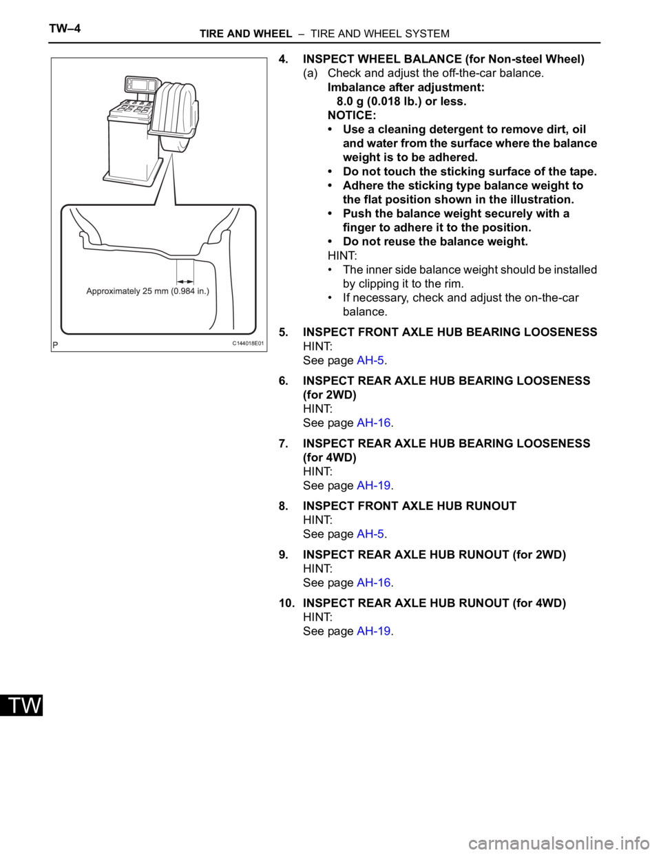
4. INSPECT WHEEL BALANCE (for Non-steel Wheel)
(a) Check and adjust the off-the-car balance.
Imbalance after adjustment:
8.0 g (0.018 lb.) or less.
NOTICE:
• Use a cleaning detergent to remove dirt, oil
and water from the surface where the balance
weight is to be adhered.
• Do not touch the sticking surface of the tape.
• Adhere the sticking type balance weight to
the flat position shown in the illustration.
• Push the balance weight securely with a
finger to adhere it to the position.
• Do not reuse the balance weight.
HINT:
• The inner side balance weight should be installed
by clipping it to the rim.
• If necessary, check and adjust the on-the-car
balance.
5. INSPECT FRONT AXLE HUB BEARING LOOSENESS
HINT:
See page AH-5.
6. INSPECT REAR AXLE HUB BEARING LOOSENESS
(for 2WD)
HINT:
See page AH-16.
7. INSPECT REAR AXLE HUB BEARING LOOSENESS
(for 4WD)
HINT:
See page AH-19.
8. INSPECT FRONT AXLE HUB RUNOUT
HINT:
See page AH-5.
9. INSPECT REAR AXLE HUB RUNOUT (for 2WD)
HINT:
See page AH-16.
10. INSPECT REAR AXLE HUB RUNOUT (for 4WD)
HINT:
See page AH-19.
C144018E01
Page 1123 of 3000
FU–22GR-FE FUEL – FUEL SYSTEM
FU
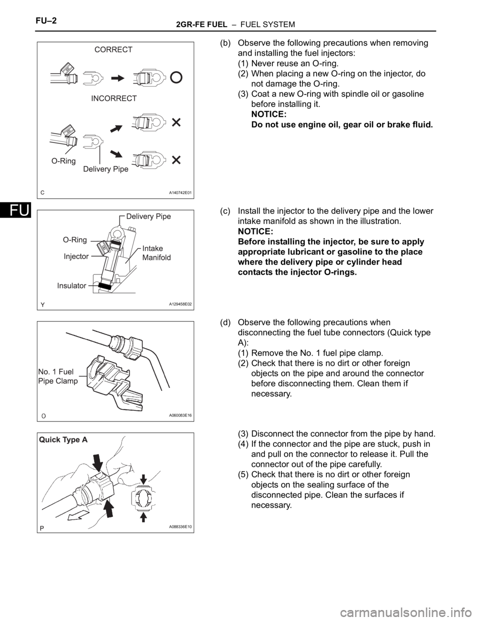
(b) Observe the following precautions when removing
and installing the fuel injectors:
(1) Never reuse an O-ring.
(2) When placing a new O-ring on the injector, do
not damage the O-ring.
(3) Coat a new O-ring with spindle oil or gasoline
before installing it.
NOTICE:
Do not use engine oil, gear oil or brake fluid.
(c) Install the injector to the delivery pipe and the lower
intake manifold as shown in the illustration.
NOTICE:
Before installing the injector, be sure to apply
appropriate lubricant or gasoline to the place
where the delivery pipe or cylinder head
contacts the injector O-rings.
(d) Observe the following precautions when
disconnecting the fuel tube connectors (Quick type
A):
(1) Remove the No. 1 fuel pipe clamp.
(2) Check that there is no dirt or other foreign
objects on the pipe and around the connector
before disconnecting them. Clean them if
necessary.
(3) Disconnect the connector from the pipe by hand.
(4) If the connector and the pipe are stuck, push in
and pull on the connector to release it. Pull the
connector out of the pipe carefully.
(5) Check that there is no dirt or other foreign
objects on the sealing surface of the
disconnected pipe. Clean the surfaces if
necessary.
A140742E01
A129458E02
A060083E16
A088336E10
Page 1124 of 3000
2GR-FE FUEL – FUEL SYSTEMFU–3
FU
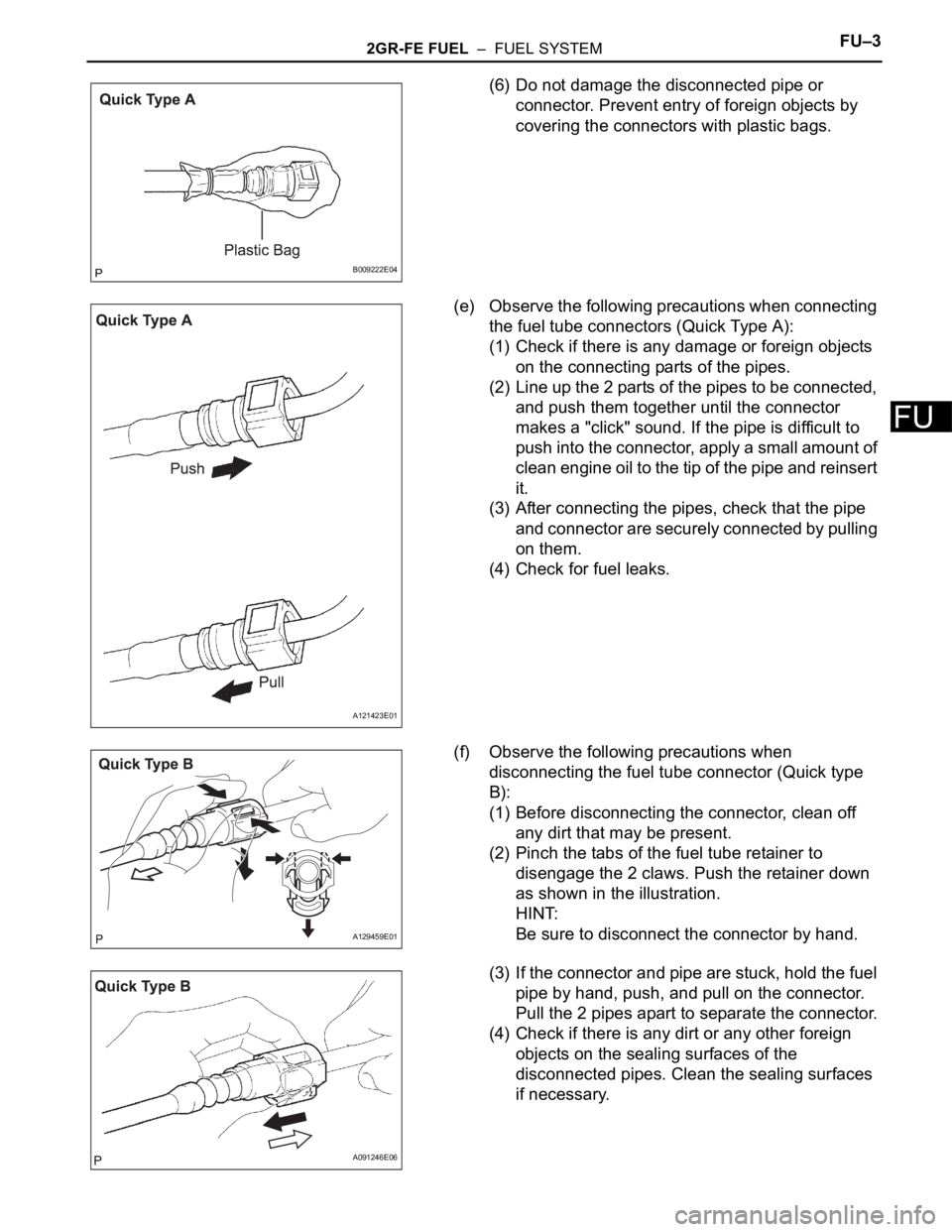
(6) Do not damage the disconnected pipe or
connector. Prevent entry of foreign objects by
covering the connectors with plastic bags.
(e) Observe the following precautions when connecting
the fuel tube connectors (Quick Type A):
(1) Check if there is any damage or foreign objects
on the connecting parts of the pipes.
(2) Line up the 2 parts of the pipes to be connected,
and push them together until the connector
makes a "click" sound. If the pipe is difficult to
push into the connector, apply a small amount of
clean engine oil to the tip of the pipe and reinsert
it.
(3) After connecting the pipes, check that the pipe
and connector are securely connected by pulling
on them.
(4) Check for fuel leaks.
(f) Observe the following precautions when
disconnecting the fuel tube connector (Quick type
B):
(1) Before disconnecting the connector, clean off
any dirt that may be present.
(2) Pinch the tabs of the fuel tube retainer to
disengage the 2 claws. Push the retainer down
as shown in the illustration.
HINT:
Be sure to disconnect the connector by hand.
(3) If the connector and pipe are stuck, hold the fuel
pipe by hand, push, and pull on the connector.
Pull the 2 pipes apart to separate the connector.
(4) Check if there is any dirt or any other foreign
objects on the sealing surfaces of the
disconnected pipes. Clean the sealing surfaces
if necessary.
B009222E04
A121423E01
A129459E01
A091246E06
Page 1125 of 3000
FU–42GR-FE FUEL – FUEL SYSTEM
FU
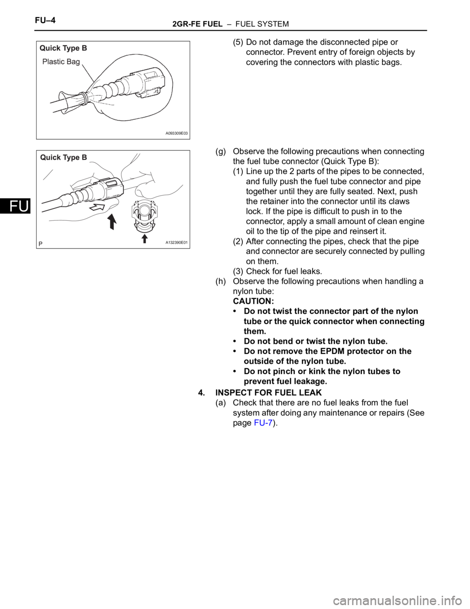
(5) Do not damage the disconnected pipe or
connector. Prevent entry of foreign objects by
covering the connectors with plastic bags.
(g) Observe the following precautions when connecting
the fuel tube connector (Quick Type B):
(1) Line up the 2 parts of the pipes to be connected,
and fully push the fuel tube connector and pipe
together until they are fully seated. Next, push
the retainer into the connector until its claws
lock. If the pipe is difficult to push in to the
connector, apply a small amount of clean engine
oil to the tip of the pipe and reinsert it.
(2) After connecting the pipes, check that the pipe
and connector are securely connected by pulling
on them.
(3) Check for fuel leaks.
(h) Observe the following precautions when handling a
nylon tube:
CAUTION:
• Do not twist the connector part of the nylon
tube or the quick connector when connecting
them.
• Do not bend or twist the nylon tube.
• Do not remove the EPDM protector on the
outside of the nylon tube.
• Do not pinch or kink the nylon tubes to
prevent fuel leakage.
4. INSPECT FOR FUEL LEAK
(a) Check that there are no fuel leaks from the fuel
system after doing any maintenance or repairs (See
page FU-7).
A093309E03
A132390E01
Page 1317 of 3000
IG–82GR-FE IGNITION – IGNITION COIL AND SPARK PLUG
IG
(2) Remove the spark plugs.
(3) Visually check the spark plug.
If the electrode is dry, the spark plug is
functioning properly. If the electrode is damp,
proceed to the next step.
(c) Check the spark plug for any damage to its threads
and insulator. If there is damage, replace the spark
plug.
Recommended spark plug
NOTICE:
Use only the listed spark plug or equivalent to
ensure engine performance and smooth
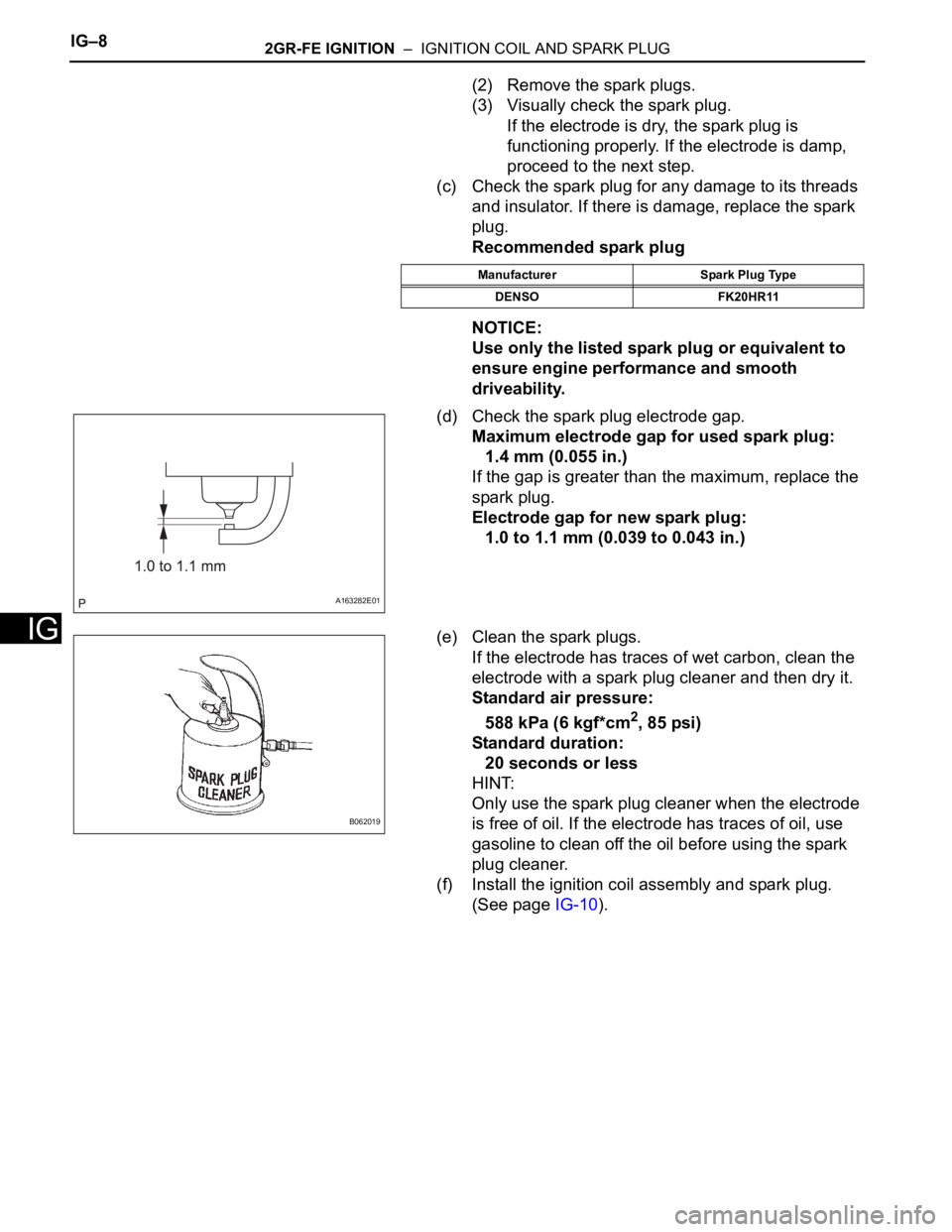
driveability.
(d) Check the spark plug electrode gap.
Maximum electrode gap for used spark plug:
1.4 mm (0.055 in.)
If the gap is greater than the maximum, replace the
spark plug.
Electrode gap for new spark plug:
1.0 to 1.1 mm (0.039 to 0.043 in.)
(e) Clean the spark plugs.
If the electrode has traces of wet carbon, clean the
electrode with a spark plug cleaner and then dry it.
Standard air pressure:
588 kPa (6 kgf*cm
2, 85 psi)
Standard duration:
20 seconds or less
HINT:
Only use the spark plug cleaner when the electrode
is free of oil. If the electrode has traces of oil, use
gasoline to clean off the oil before using the spark
plug cleaner.
(f) Install the ignition coil assembly and spark plug.
(See page IG-10).
Manufacturer Spark Plug Type
DENSO FK20HR11
A163282E01
B062019
Page 1514 of 3000
U151E AUTOMATIC TRANSAXLE – TRANSMISSION WIREAX–131
AX
REMOVAL
1. DISCONNECT CABLE FROM NEGATIVE BATTERY
TERMINAL
2. REMOVE ENGINE UNDER COVER NO.1
3. DRAIN AUTOMATIC TRANSAXLE FLUID
(a) Remove the drain plug and gasket, and drain the
AT F.
(b) Install a new gasket and the drain plug.
Torque: 49 N*m (500 kgf*cm, 36 ft.*lbf)
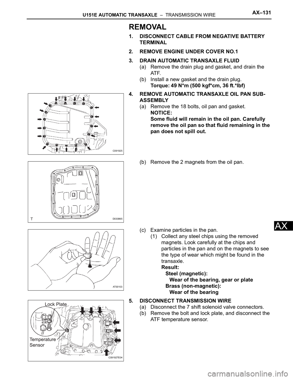
4. REMOVE AUTOMATIC TRANSAXLE OIL PAN SUB-
ASSEMBLY
(a) Remove the 18 bolts, oil pan and gasket.
NOTICE:
Some fluid will remain in the oil pan. Carefully
remove the oil pan so that fluid remaining in the
pan does not spill out.
(b) Remove the 2 magnets from the oil pan.
(c) Examine particles in the pan.
(1) Collect any steel chips using the removed
magnets. Look carefully at the chips and
particles in the pan and on the magnets to see
the type of wear which might be found in the
transaxle.
Result:
Steel (magnetic):
Wear of the bearing, gear or plate
Brass (non-magnetic):
Wear of the bearing
5. DISCONNECT TRANSMISSION WIRE
(a) Disconnect the 7 shift solenoid valve connectors.
(b) Remove the bolt and lock plate, and disconnect the
ATF temperature sensor.
C091925
D030865
AT00103
C091927E04
Page 1519 of 3000
AX–136U151E AUTOMATIC TRANSAXLE – VALVE BODY ASSEMBLY
AX
REMOVAL
1. REMOVE ENGINE UNDER COVER NO.1
2. DISCONNECT CABLE FROM NEGATIVE BATTERY
TERMINAL
3. DRAIN AUTOMATIC TRANSAXLE FLUID (See page
AX-131)
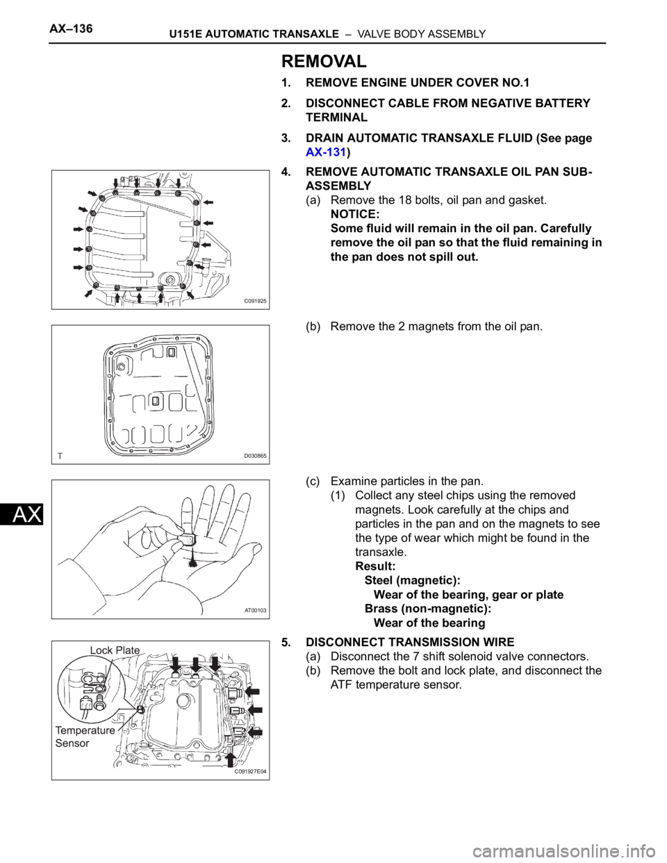
4. REMOVE AUTOMATIC TRANSAXLE OIL PAN SUB-
ASSEMBLY
(a) Remove the 18 bolts, oil pan and gasket.
NOTICE:
Some fluid will remain in the oil pan. Carefully
remove the oil pan so that the fluid remaining in
the pan does not spill out.
(b) Remove the 2 magnets from the oil pan.
(c) Examine particles in the pan.
(1) Collect any steel chips using the removed
magnets. Look carefully at the chips and
particles in the pan and on the magnets to see
the type of wear which might be found in the
transaxle.
Result:
Steel (magnetic):
Wear of the bearing, gear or plate
Brass (non-magnetic):
Wear of the bearing
5. DISCONNECT TRANSMISSION WIRE
(a) Disconnect the 7 shift solenoid valve connectors.
(b) Remove the bolt and lock plate, and disconnect the
ATF temperature sensor.
C091925
D030865
AT00103
C091927E04