2007 TOYOTA SIENNA steering wheel adjustment
[x] Cancel search: steering wheel adjustmentPage 2453 of 3000

BRAKE CONTROL – VEHICLE STABILITY CONTROL SYSTEMBC–91
BC
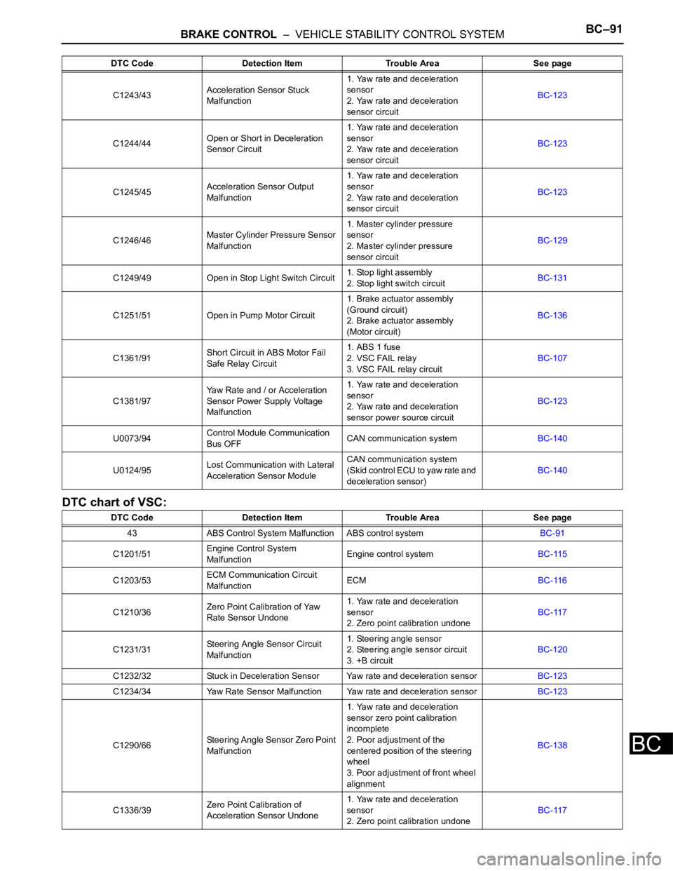
DTC chart of VSC:
C1243/43Acceleration Sensor Stuck
Malfunction1. Yaw rate and deceleration
sensor
2. Yaw rate and deceleration
sensor circuitBC-123
C1244/44Open or Short in Deceleration
Sensor Circuit1. Yaw rate and deceleration
sensor
2. Yaw rate and deceleration
sensor circuitBC-123
C1245/45Acceleration Sensor Output
Malfunction1. Yaw rate and deceleration
sensor
2. Yaw rate and deceleration
sensor circuitBC-123
C1246/46Master Cylinder Pressure Sensor
Malfunction1. Master cylinder pressure
sensor
2. Master cylinder pressure
sensor circuitBC-129
C1249/49 Open in Stop Light Switch Circuit1. Stop light assembly
2. Stop light switch circuitBC-131
C1251/51 Open in Pump Motor Circuit1. Brake actuator assembly
(Ground circuit)
2. Brake actuator assembly
(Motor circuit)BC-136
C1361/91Short Circuit in ABS Motor Fail
Safe Relay Circuit1. ABS 1 fuse
2. VSC FAIL relay
3. VSC FAIL relay circuitBC-107
C1381/97Yaw Rate and / or Acceleration
Sensor Power Supply Voltage
Malfunction1. Yaw rate and deceleration
sensor
2. Yaw rate and deceleration
sensor power source circuitBC-123
U0073/94Control Module Communication
Bus OFFCAN communication systemBC-140
U0124/95Lost Communication with Lateral
Acceleration Sensor ModuleCAN communication system
(Skid control ECU to yaw rate and
deceleration sensor)BC-140
DTC Code Detection Item Trouble Area See page
43 ABS Control System Malfunction ABS control systemBC-91
C1201/51Engine Control System
MalfunctionEngine control systemBC-115
C1203/53ECM Communication Circuit
MalfunctionECMBC-116
C1210/36Zero Point Calibration of Yaw
Rate Sensor Undone1. Yaw rate and deceleration
sensor
2. Zero point calibration undoneBC-117
C1231/31Steering Angle Sensor Circuit
Malfunction1. Steering angle sensor
2. Steering angle sensor circuit
3. +B circuitBC-120
C1232/32 Stuck in Deceleration Sensor Yaw rate and deceleration sensorBC-123
C1234/34 Yaw Rate Sensor Malfunction Yaw rate and deceleration sensorBC-123
C1290/66Steering Angle Sensor Zero Point
Malfunction1. Yaw rate and deceleration
sensor zero point calibration
incomplete
2. Poor adjustment of the
centered position of the steering
wheel
3. Poor adjustment of front wheel
alignmentBC-138
C1336/39Zero Point Calibration of
Acceleration Sensor Undone1. Yaw rate and deceleration
sensor
2. Zero point calibration undoneBC-117 DTC Code Detection Item Trouble Area See page
Page 2502 of 3000

BC–140BRAKE CONTROL – VEHICLE STABILITY CONTROL SYSTEM
BC
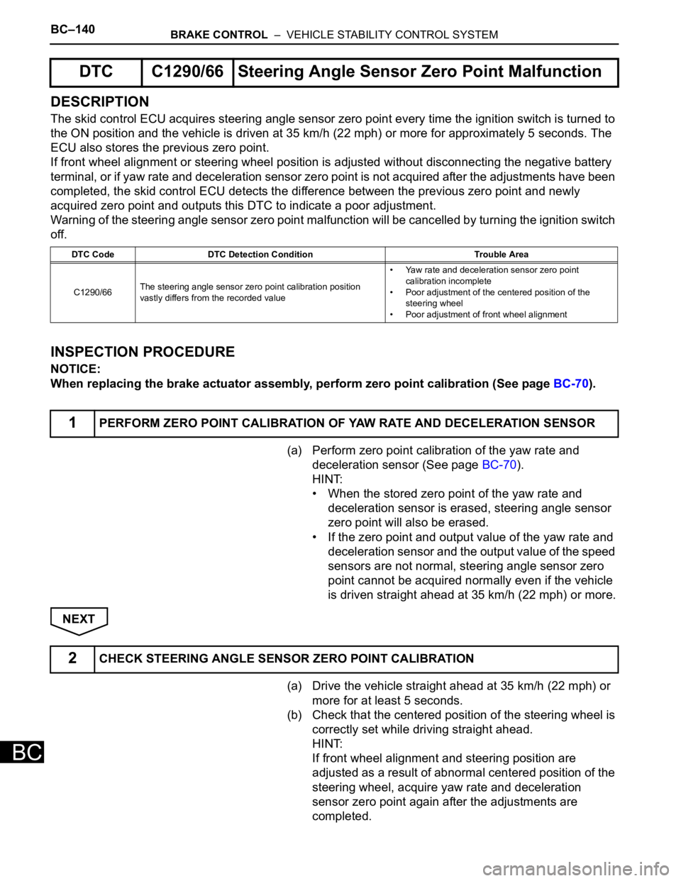
DESCRIPTION
The skid control ECU acquires steering angle sensor zero point every time the ignition switch is turned to
the ON position and the vehicle is driven at 35 km/h (22 mph) or more for approximately 5 seconds. The
ECU also stores the previous zero point.
If front wheel alignment or steering wheel position is adjusted without disconnecting the negative battery
terminal, or if yaw rate and deceleration sensor zero point is not acquired after the adjustments have been
completed, the skid control ECU detects the difference between the previous zero point and newly
acquired zero point and outputs this DTC to indicate a poor adjustment.
Warning of the steering angle sensor zero point malfunction will be cancelled by turning the ignition switch
off.
INSPECTION PROCEDURE
NOTICE:
When replacing the brake actuator assembly, perform zero point calibration (See page BC-70).
(a) Perform zero point calibration of the yaw rate and
deceleration sensor (See page BC-70).
HINT:
• When the stored zero point of the yaw rate and
deceleration sensor is erased, steering angle sensor
zero point will also be erased.
• If the zero point and output value of the yaw rate and
deceleration sensor and the output value of the speed
sensors are not normal, steering angle sensor zero
point cannot be acquired normally even if the vehicle
is driven straight ahead at 35 km/h (22 mph) or more.
NEXT
(a) Drive the vehicle straight ahead at 35 km/h (22 mph) or
more for at least 5 seconds.
(b) Check that the centered position of the steering wheel is
correctly set while driving straight ahead.
HINT:
If front wheel alignment and steering position are
adjusted as a result of abnormal centered position of the
steering wheel, acquire yaw rate and deceleration
sensor zero point again after the adjustments are
completed.
DTC C1290/66 Steering Angle Sensor Zero Point Malfunction
DTC Code DTC Detection Condition Trouble Area
C1290/66The steering angle sensor zero point calibration position
vastly differs from the recorded value• Yaw rate and deceleration sensor zero point
calibration incomplete
• Poor adjustment of the centered position of the
steering wheel
• Poor adjustment of front wheel alignment
1PERFORM ZERO POINT CALIBRATION OF YAW RATE AND DECELERATION SENSOR
2CHECK STEERING ANGLE SENSOR ZERO POINT CALIBRATION
Page 2678 of 3000

SR–2STEERING COLUMN – STEERING SYSTEM
SR
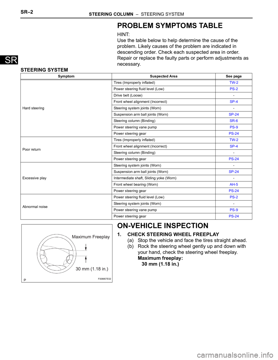
PROBLEM SYMPTOMS TABLE
HINT:
Use the table below to help determine the cause of the
problem. Likely causes of the problem are indicated in
descending order. Check each suspected area in order.
Repair or replace the faulty parts or perform adjustments as
necessary.
STEERING SYSTEM
ON-VEHICLE INSPECTION
1. CHECK STEERING WHEEL FREEPLAY
(a) Stop the vehicle and face the tires straight ahead.
(b) Rock the steering wheel gently up and down with
your hand, check the steering wheel freeplay.
Maximum freeplay:
30 mm (1.18 in.)
Symptom Suspected Area See page
Hard steeringTires (Improperly inflated)TW-2
Power steering fluid level (Low)PS-2
Drive belt (Loose) -
Front wheel alignment (Incorrect)SP-4
Steering system joints (Worn) -
Suspension arm ball joints (Worn)SP-24
Steering column (Binding)SR-6
Power steering vane pumpPS-9
Power steering gearPS-24
Poor returnTires (Improperly inflated)TW-2
Front wheel alignment (Incorrect)SP-4
Steering column (Binding) -
Power steering gearPS-24
Excessive playSteering system joints (Worn) -
Suspension arm ball joints (Worn)SP-24
Intermediate shaft, Sliding yoke (Worn) -
Front wheel bearing (Worn)AH-5
Power steering gearPS-24
Abnormal noisePower steering fluid level (Low)PS-2
Steering system joints (Worn) -
Power steering vane pumpPS-9
Power steering gearPS-24
F008857E02
Page 2712 of 3000

PS–2POWER STEERING – POWER STEERING SYSTEM
PS
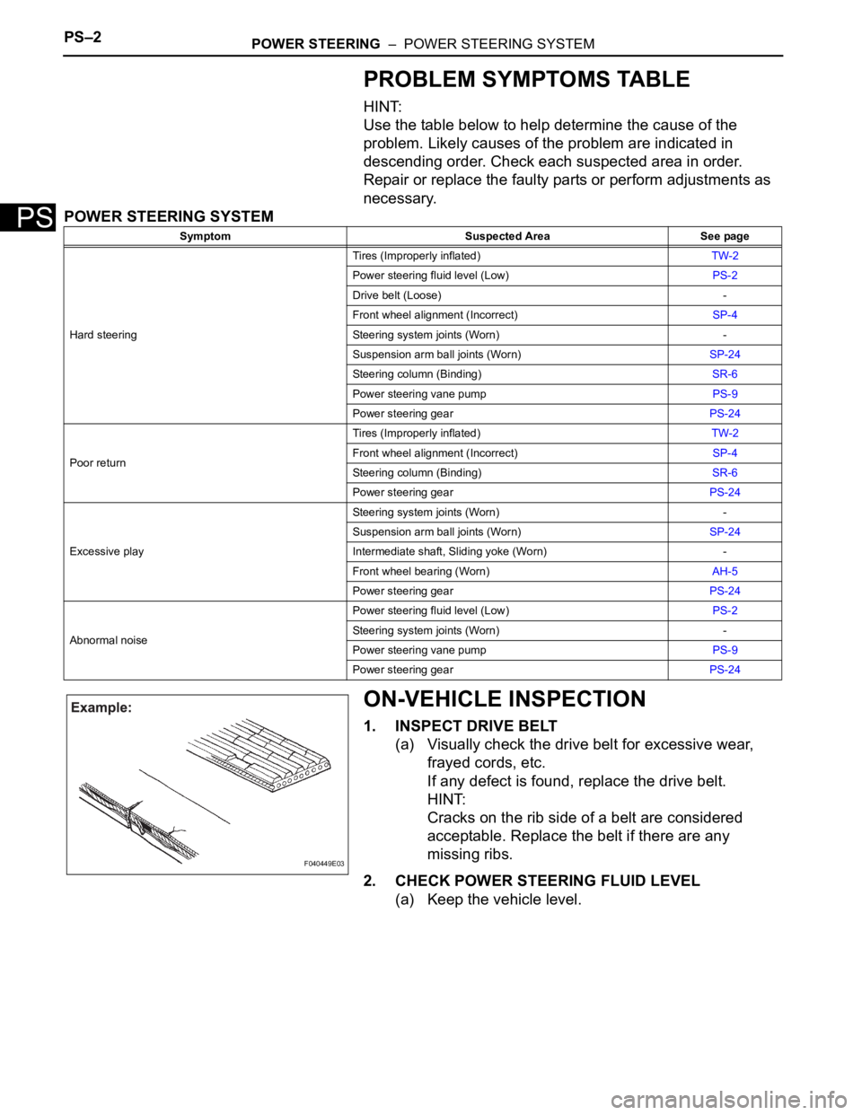
PROBLEM SYMPTOMS TABLE
HINT:
Use the table below to help determine the cause of the
problem. Likely causes of the problem are indicated in
descending order. Check each suspected area in order.
Repair or replace the faulty parts or perform adjustments as
necessary.
POWER STEERING SYSTEM
ON-VEHICLE INSPECTION
1. INSPECT DRIVE BELT
(a) Visually check the drive belt for excessive wear,
frayed cords, etc.
If any defect is found, replace the drive belt.
HINT:
Cracks on the rib side of a belt are considered
acceptable. Replace the belt if there are any
missing ribs.
2. CHECK POWER STEERING FLUID LEVEL
(a) Keep the vehicle level.
Symptom Suspected Area See page
Hard steeringTires (Improperly inflated)TW-2
Power steering fluid level (Low)PS-2
Drive belt (Loose) -
Front wheel alignment (Incorrect)SP-4
Steering system joints (Worn) -
Suspension arm ball joints (Worn)SP-24
Steering column (Binding)SR-6
Power steering vane pumpPS-9
Power steering gearPS-24
Poor returnTires (Improperly inflated)TW-2
Front wheel alignment (Incorrect)SP-4
Steering column (Binding)SR-6
Power steering gearPS-24
Excessive playSteering system joints (Worn) -
Suspension arm ball joints (Worn)SP-24
Intermediate shaft, Sliding yoke (Worn) -
Front wheel bearing (Worn)AH-5
Power steering gearPS-24
Abnormal noisePower steering fluid level (Low)PS-2
Steering system joints (Worn) -
Power steering vane pumpPS-9
Power steering gearPS-24
F040449E03