2007 TOYOTA SIENNA wiring diagram
[x] Cancel search: wiring diagramPage 55 of 3000
INTRODUCTION – HOW TO TROUBLESHOOT ECU CONTROLLED SYSTEMSIN–43
IN
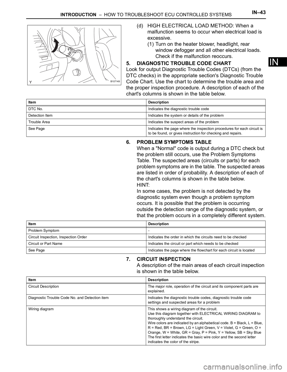
(d) HIGH ELECTRICAL LOAD METHOD: When a
malfunction seems to occur when electrical load is
excessive.
(1) Turn on the heater blower, headlight, rear
window defogger and all other electrical loads.
Check if the malfunction reoccurs.
5. DIAGNOSTIC TROUBLE CODE CHART
Look for output Diagnostic Trouble Codes (DTCs) (from the
DTC checks) in the appropriate section's Diagnostic Trouble
Code Chart. Use the chart to determine the trouble area and
the proper inspection procedure. A description of each of the
chart's columns is shown in the table below.
6. PROBLEM SYMPTOMS TABLE
When a "Normal" code is output during a DTC check but
the problem still occurs, use the Problem Symptoms
Table. The suspected areas (circuits or parts) for each
problem symptoms are in the table. The suspected areas
are listed in order of probability. A description of each of
the chart's columns is shown in the table below.
HINT:
In some cases, the problem is not detected by the
diagnostic system even though a problem symptom
occurs. It is possible that the problem is occurring
outside the detection range of the diagnostic system, or
that the problem occurs in a completely different system.
7. CIRCUIT INSPECTION
A description of the main areas of each circuit inspection
is shown in the table below.
B107149
Item Description
DTC No. Indicates the diagnostic trouble code
Detection Item Indicates the system or details of the problem
Trouble Area Indicates the suspect areas of the problem
See Page Indicates the page where the inspection procedures for each circuit is
to be found, or gives instruction for checking and repairs.
Item Description
Problem Symptom -
Circuit Inspection, Inspection Order Indicates the order in which the circuits need to be checked
Circuit or Part Name Indicates the circuit or part which needs to be checked
See Page Indicates the page where the flowchart for each circuit is located
Item Description
Circuit Description The major role, operation of the circuit and its component parts are
explained.
Diagnostic Trouble Code No. and Detection item Indicates the diagnostic trouble codes, diagnostic trouble code
settings and suspected areas for a problem
Wiring diagram This shows a wiring diagram of the circuit.
Use this diagram together with ELECTRICAL WIRING DIAGRAM to
thoroughly understand the circuit.
Wire colors are indicated by an alphabetical code. B = Black, L = Blue,
R = Red, BR = Brown, LG = Light Green, V = Violet, G = Green, O =
Orange, W = White, GR = Gray, P = Pink, Y = Yellow, SB = Sky Blue
The first letter indicates the basic wire color and the second letter
indicates the color of the stripe.
Page 73 of 3000
INTRODUCTION – HOW TO TROUBLESHOOT ECU CONTROLLED SYSTEMSIN–43
IN
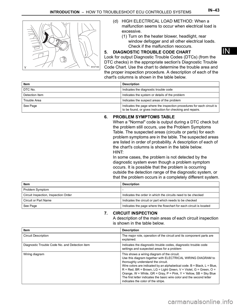
(d) HIGH ELECTRICAL LOAD METHOD: When a
malfunction seems to occur when electrical load is
excessive.
(1) Turn on the heater blower, headlight, rear
window defogger and all other electrical loads.
Check if the malfunction reoccurs.
5. DIAGNOSTIC TROUBLE CODE CHART
Look for output Diagnostic Trouble Codes (DTCs) (from the
DTC checks) in the appropriate section's Diagnostic Trouble
Code Chart. Use the chart to determine the trouble area and
the proper inspection procedure. A description of each of the
chart's columns is shown in the table below.
6. PROBLEM SYMPTOMS TABLE
When a "Normal" code is output during a DTC check but
the problem still occurs, use the Problem Symptoms
Table. The suspected areas (circuits or parts) for each
problem symptoms are in the table. The suspected areas
are listed in order of probability. A description of each of
the chart's columns is shown in the table below.
HINT:
In some cases, the problem is not detected by the
diagnostic system even though a problem symptom
occurs. It is possible that the problem is occurring
outside the detection range of the diagnostic system, or
that the problem occurs in a completely different system.
7. CIRCUIT INSPECTION
A description of the main areas of each circuit inspection
is shown in the table below.
B107149
Item Description
DTC No. Indicates the diagnostic trouble code
Detection Item Indicates the system or details of the problem
Trouble Area Indicates the suspect areas of the problem
See Page Indicates the page where the inspection procedures for each circuit is
to be found, or gives instruction for checking and repairs.
Item Description
Problem Symptom -
Circuit Inspection, Inspection Order Indicates the order in which the circuits need to be checked
Circuit or Part Name Indicates the circuit or part which needs to be checked
See Page Indicates the page where the flowchart for each circuit is located
Item Description
Circuit Description The major role, operation of the circuit and its component parts are
explained.
Diagnostic Trouble Code No. and Detection item Indicates the diagnostic trouble codes, diagnostic trouble code
settings and suspected areas for a problem
Wiring diagram This shows a wiring diagram of the circuit.
Use this diagram together with ELECTRICAL WIRING DIAGRAM to
thoroughly understand the circuit.
Wire colors are indicated by an alphabetical code. B = Black, L = Blue,
R = Red, BR = Brown, LG = Light Green, V = Violet, G = Green, O =
Orange, W = White, GR = Gray, P = Pink, Y = Yellow, SB = Sky Blue
The first letter indicates the basic wire color and the second letter
indicates the color of the stripe.
Page 322 of 3000
ES–2542GR-FE ENGINE CONTROL SYSTEM – SFI SYSTEM
ES
Exhaust Camshaft Sensor Range Check (Low voltage):
Exhaust Camshaft Sensor Range Check (High voltage):
WIRING DIAGRAM
Refer to DTC P0335 (See page ES-222).
INSPECTION PROCEDURE
HINT:
Read freeze frame data using the intelligent tester. The ECM records vehicle and driving condition
information as freeze frame data the moment a DTC is stored. When troubleshooting, freeze frame data
can be helpful in determining whether the vehicle was running or stopped, whether the engine was
warmed up or not, whether the air-fuel ratio was lean or rich, as well as other data recorded at the time of
a malfunction.
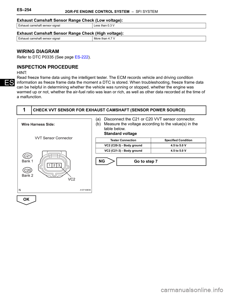
(a) Disconnect the C21 or C20 VVT sensor connector.
(b) Measure the voltage according to the value(s) in the
table below.
Standard voltage
NG
OK
Exhaust camshaft sensor signal Less than 0.3 V
Exhaust camshaft sensor signal More than 4.7 V
1CHECK VVT SENSOR FOR EXHAUST CAMSHAFT (SENSOR POWER SOURCE)
A107149E59
Tester Connection Specified Condition
VC2 (C20-3) - Body ground 4.5 to 5.0 V
VC2 (C21-3) - Body ground 4.5 to 5.0 V
Go to step 7
Page 334 of 3000
ES–4062GR-FE ENGINE CONTROL SYSTEM – SFI SYSTEM
ES
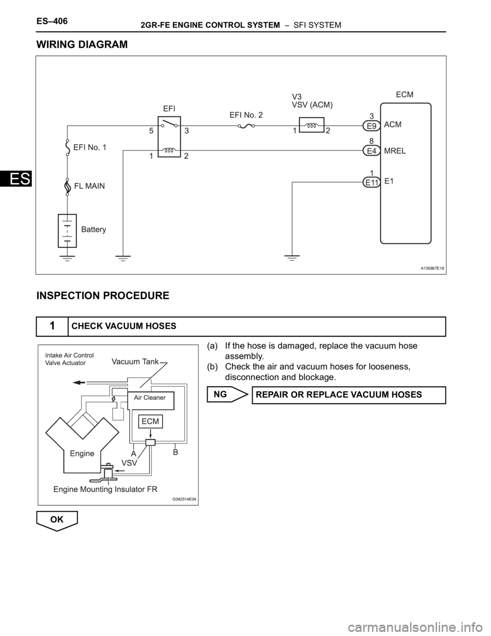
WIRING DIAGRAM
INSPECTION PROCEDURE
(a) If the hose is damaged, replace the vacuum hose
assembly.
(b) Check the air and vacuum hoses for looseness,
disconnection and blockage.
NG
OK
1CHECK VACUUM HOSES
A136867E18
G042514E04
REPAIR OR REPLACE VACUUM HOSES
Page 391 of 3000
2GR-FE ENGINE CONTROL SYSTEM – SFI SYSTEMES–85
ES
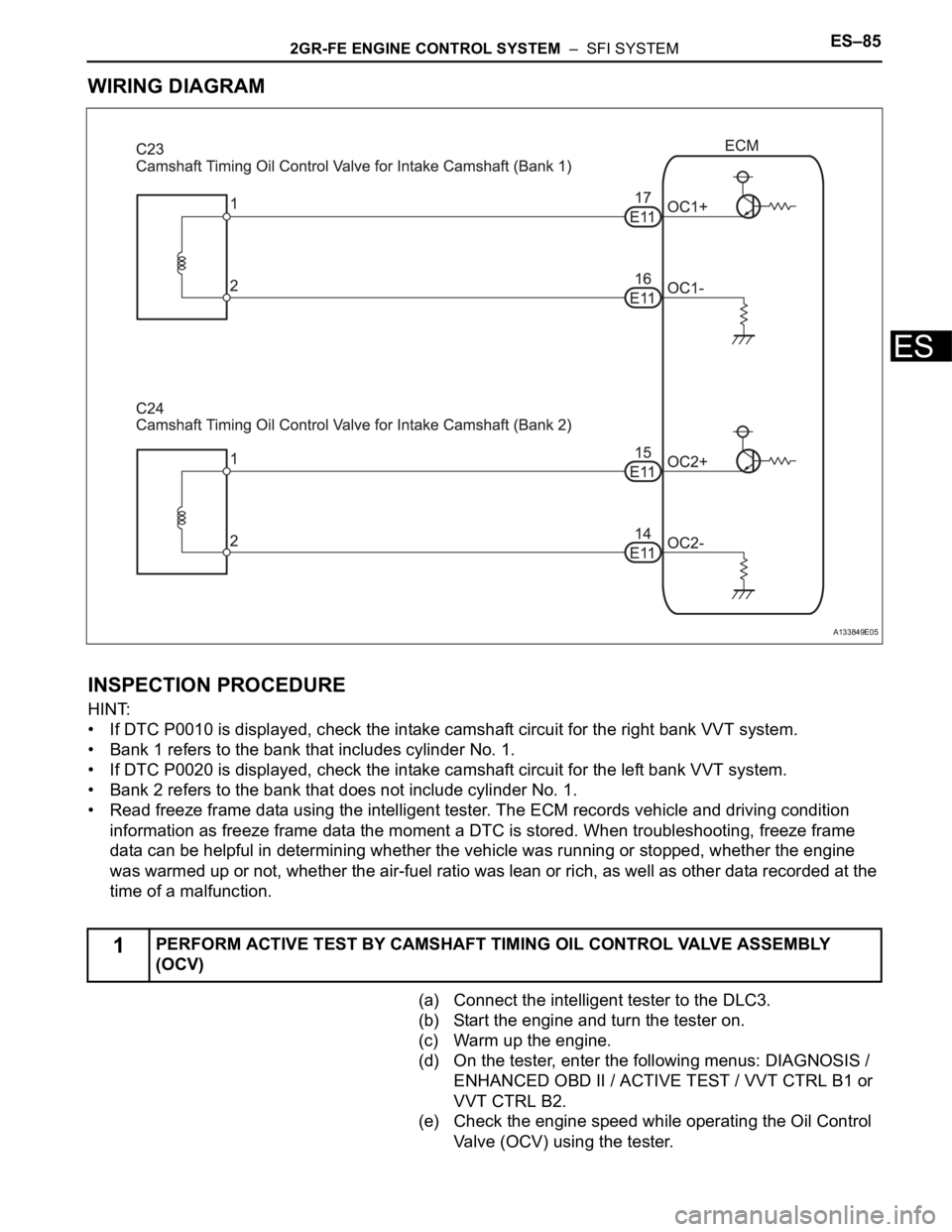
WIRING DIAGRAM
INSPECTION PROCEDURE
HINT:
• If DTC P0010 is displayed, check the intake camshaft circuit for the right bank VVT system.
• Bank 1 refers to the bank that includes cylinder No. 1.
• If DTC P0020 is displayed, check the intake camshaft circuit for the left bank VVT system.
• Bank 2 refers to the bank that does not include cylinder No. 1.
• Read freeze frame data using the intelligent tester. The ECM records vehicle and driving condition
information as freeze frame data the moment a DTC is stored. When troubleshooting, freeze frame
data can be helpful in determining whether the vehicle was running or stopped, whether the engine
was warmed up or not, whether the air-fuel ratio was lean or rich, as well as other data recorded at the
time of a malfunction.
(a) Connect the intelligent tester to the DLC3.
(b) Start the engine and turn the tester on.
(c) Warm up the engine.
(d) On the tester, enter the following menus: DIAGNOSIS /
ENHANCED OBD II / ACTIVE TEST / VVT CTRL B1 or
VVT CTRL B2.
(e) Check the engine speed while operating the Oil Control
Valve (OCV) using the tester.
1PERFORM ACTIVE TEST BY CAMSHAFT TIMING OIL CONTROL VALVE ASSEMBLY
(OCV)
A133849E05
Page 395 of 3000

2GR-FE ENGINE CONTROL SYSTEM – SFI SYSTEMES–89
ES
3) After above conditions 1) and 2) are met, the OCV is forcibly activated 63 times or more.
DTCs P0011 and P0021 (Advanced Cam Timing) are detected with 1 trip detection logic.
DTCs P0012 and P0022 (Retarded Cam Timing) are detected with 2 trip detection logic.
These DTCs indicate that the VVT controller cannot operate properly due to OCV malfunctions or the
presence of foreign objects in the OCV.
The monitor will not run unless the following conditions are met:
- The engine is warm (the engine coolant temperature is 75
C [167F] or more).
- The vehicle has been driven at more than 40 mph (64 km/h) for 3 minutes.
- The engine has idled for 3 minutes.
MONITOR STRATEGY
TYPICAL ENABLING CONDITIONS
TYPICAL MALFUNCTION THRESHOLDS
P0011, P0021:
P0012, P0022:
If the difference between the target and actual camshaft timings is greater than the specified value, the
ECM operates the VVT actuator.
Then, the ECM monitors the camshaft timing change for 5 seconds.
WIRING DIAGRAM
Refer to DTC P0010 (See page ES-77).
INSPECTION PROCEDURE
Related DTCsP0011: Advanced intake camshaft timing (bank 1)
P0012: Retarded intake camshaft timing (bank 1)
P0021: Advanced intake camshaft timing (bank 2)
P0022: Retarded intake camshaft timing (bank 2)
Required sensors / components (Main) VVT OCV, VVT Actuator
Required sensors / components (Related) Crankshaft position sensor, Camshaft position sensor, ECT sensor
Frequency of operation Once per driving cycles
Duration Less than 10 seconds
MIL operationP0011 and P0021: Immediate
P0012 and P0022: 2 driving cycles
Sequence operation None
The monitor will run whenever these DTCs are not
presentP0100, P0101, P0102, P0103 (MAF Sensor), P0115, P0116, P0117, P0118 (ECT
Sensor), P0125 (Insufficient ECT for Closed Loop), P0335 (CKP Sensor), P0340
(CMP Sensor), P0351, P0352, P0353, P0354, P0355, P0356 (Ignitor)
Battery voltage 11 V or more
Engine RPM 500 to 4000 rpm
ECT 75 to 100
C (167 to 212F)
Duration of actual valve timing and target valve timing More than 5
CA (Crankshaft angle)
Valve timing No change in advanced valve timing
Duration of actual valve timing and target valve timing More than 5
CA (Crankshaft angle)
Valve timing No change in retarded valve timing
Abnormal bankAdvanced timing over
(Valve timing is out of specified range)Retarded timing over
(Valve timing is out of specified range)
Bank 1 P0011 P0012
Bank 2 P0021 P0022
Page 403 of 3000
2GR-FE ENGINE CONTROL SYSTEM – SFI SYSTEMES–97
ES
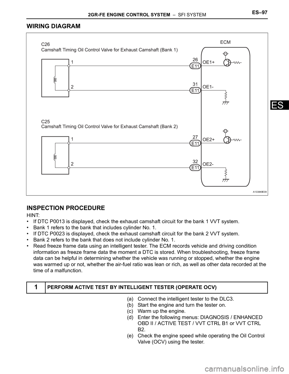
WIRING DIAGRAM
INSPECTION PROCEDURE
HINT:
• If DTC P0013 is displayed, check the exhaust camshaft circuit for the bank 1 VVT system.
• Bank 1 refers to the bank that includes cylinder No. 1.
• If DTC P0023 is displayed, check the exhaust camshaft circuit for the bank 2 VVT system.
• Bank 2 refers to the bank that does not include cylinder No. 1.
• Read freeze frame data using an intelligent tester. The ECM records vehicle and driving condition
information as freeze frame data the moment a DTC is stored. When troubleshooting, freeze frame
data can be helpful in determining whether the vehicle was running or stopped, whether the engine
was warmed up or not, whether the air-fuel ratio was lean or rich, as well as other data recorded at the
time of a malfunction.
(a) Connect the intelligent tester to the DLC3.
(b) Start the engine and turn the tester on.
(c) Warm up the engine.
(d) Enter the following menus: DIAGNOSIS / ENHANCED
OBD II / ACTIVE TEST / VVT CTRL B1 or VVT CTRL
B2.
(e) Check the engine speed while operating the Oil Control
Valve (OCV) using the tester.
1PERFORM ACTIVE TEST BY INTELLIGENT TESTER (OPERATE OCV)
A133849E09
Page 407 of 3000

2GR-FE ENGINE CONTROL SYSTEM – SFI SYSTEMES–101
ES
MONITOR STRATEGY
TYPICAL ENABLING CONDITIONS
TYPICAL MALFUNCTION THRESHOLDS
Advanced camshaft timing:
Retarded camshaft timing:
If the difference between the target and actual camshaft timings is greater than the specified value, the
ECM operates the VVT actuator.
Then, the ECM monitors the camshaft timing change for 5 seconds.
WIRING DIAGRAM
Refer to DTC P0013 (See page ES-89).
INSPECTION PROCEDURE
HINT:
• If DTC P0014 or P0015 is displayed, check the bank 1 VVT system circuit.
• Bank 1 refers to the bank that includes cylinder No. 1.
• If DTC P0024 or P0025 is displayed, check the bank 2 VVT system circuit.
• Bank 2 refers to the bank that does not include cylinder No. 1.
Related DTCsP0014: Advanced exhaust camshaft timing (bank 1)
P0015: Retarded exhaust camshaft timing (bank 1)
P0024: Advanced exhaust camshaft timing (bank 2)
P0025: Retarded exhaust camshaft timing (bank 2)
Required Sensors / Components (Main) VVT OCV and VVT Actuator
Required Sensors / Components (Related)P0014 and P0015:
Exhaust camshaft control actuator bank 1
Exhaust OCV bank 1
P0024 and P0025:
Exhaust camshaft control actuator bank 2
Exhaust OCV bank 2
Frequency of Operation Continuously
Duration Less than 10 seconds
MIL OperationP0014 and P0024: Immediate
P0015 and P0025: 2 driving cycles
Sequence of Operation None
The monitor will run whenever these DTCs are not
presentNone
Battery voltage 11 V or more
Engine RPM 500 to 4000 rpm
Engine coolant temperature 75 to 100
C (167 to 212F)
Valve timing No change
Valve timing Advanced position
Valve timing No change
Valve timing Retarded position
Abnormal bankAdvanced timing over
(Valve timing is out of specified range)Retarded timing over
(Valve timing is out of specified range)
Bank 1 P0014 P0015
Bank 2 P0024 P0025