2007 TOYOTA SIENNA fuel cap release
[x] Cancel search: fuel cap releasePage 44 of 3000

2GR-FE EMISSION CONTROL – EMISSION CONTROL SYSTEMEC–5
EC
ON-VEHICLE INSPECTION
1. INSPECT FUEL CUT RPM
(a) Increase the engine speed to at least 3500 rpm.
(b) Use a sound scope to check for injector operating
sounds.
(c) Check that when the throttle lever is released,
injector operating sounds stop momentarily (at 2500
rpm) and then resume (at 1400 rpm).
Standard
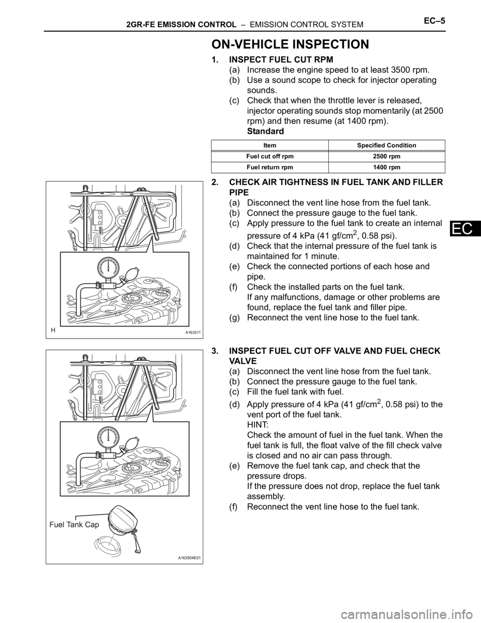
2. CHECK AIR TIGHTNESS IN FUEL TANK AND FILLER
PIPE
(a) Disconnect the vent line hose from the fuel tank.
(b) Connect the pressure gauge to the fuel tank.
(c) Apply pressure to the fuel tank to create an internal
pressure of 4 kPa (41 gf/cm
2, 0.58 psi).
(d) Check that the internal pressure of the fuel tank is
maintained for 1 minute.
(e) Check the connected portions of each hose and
pipe.
(f) Check the installed parts on the fuel tank.
If any malfunctions, damage or other problems are
found, replace the fuel tank and filler pipe.
(g) Reconnect the vent line hose to the fuel tank.
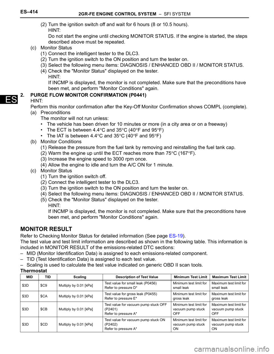
3. INSPECT FUEL CUT OFF VALVE AND FUEL CHECK
VA LV E
(a) Disconnect the vent line hose from the fuel tank.
(b) Connect the pressure gauge to the fuel tank.
(c) Fill the fuel tank with fuel.
(d) Apply pressure of 4 kPa (41 gf/cm
2, 0.58 psi) to the
vent port of the fuel tank.
HINT:
Check the amount of fuel in the fuel tank. When the
fuel tank is full, the float valve of the fill check valve
is closed and no air can pass through.
(e) Remove the fuel tank cap, and check that the
pressure drops.
If the pressure does not drop, replace the fuel tank
assembly.
(f) Reconnect the vent line hose to the fuel tank.
Item Specified Condition
Fuel cut off rpm 2500 rpm
Fuel return rpm 1400 rpm
A163311
A163504E01
Page 326 of 3000

ES–2582GR-FE ENGINE CONTROL SYSTEM – SFI SYSTEM
ES
MONITOR DESCRIPTION
The ECM uses the sensors mounted in front of and behind the three-way catalyst (TWC) to monitor its
efficiency. The first sensor, an Air Fuel ratio (A/F) sensor, sends pre-catalyst A/F ratio information to the
ECM. The second sensor, a heated oxygen sensor (O2S), sends post-catalyst information to the ECM.
The ECM compares these 2 signals to judge the efficiency of the catalyst and the catalyst's ability to store
oxygen. During normal operation, the TWC stores and releases oxygen as needed. The capacity to store
oxygen results in a low variation in the post-TWC exhaust stream.
If the catalyst is functioning normally, the waveform of the heated oxygen sensor slowly switches between
RICH and LEAN. If the catalyst is deteriorated, the waveform will alternate frequently between RICH and
LEAN. As the catalyst efficiency degrades, its ability to store oxygen is reduced and the catalyst output
becomes more variable. When running the monitor, the ECM compares sensor 1 signals (A/F sensor)
over a specific amount of time to determine catalyst efficiency. The ECM begins by calculating the signal
length for both sensors (for the rear oxygen sensor, the ECM uses the output voltage signal length). If the
oxygen sensor output voltage signal length is greater than the threshold (threshold is calculated based on
the A/F sensor signal length), the ECM concludes that the catalyst is malfunctioning. The ECM will turn on
the MIL and a DTC will be set.
HINT:
• Bank 1 refers to the bank that includes cylinder No. 1.
• Bank 2 refers to the bank that does not include cylinder No. 1.
• Sensor 1 refers to the sensor closest to the engine assembly.
• Sensor 2 refers to the sensor farthest away from the engine assembly.
MONITOR STRATEGY
DTC P0420Catalyst System Efficiency Below Threshold
(Bank 1)
DTC P0430Catalyst System Efficiency Below Threshold
(Bank 2)
DTC No. DTC Detection Condition Trouble Area
P0420Oxygen Storage Capacity (OSC) value is smaller than
standard value under active air-fuel ratio control (2 trip
detection logic)• Gas leakage from exhaust system
• A/F sensor (bank 1 sensor 1)
• HO2 sensor (bank 1 sensor 2)
• Exhaust manifold (TWC)
P0430OSC value is smaller than standard value under active
air-fuel ratio control (2 trip detection logic)• Gas leakage from exhaust system
• A/F sensor (bank 2 sensor 1)
• HO2 sensor (bank 2 sensor 2)
• Exhaust manifold (TWC)
Related DTCsP0420: Catalyst Deterioration
P0430: Catalyst Deterioration
Required Sensors / Components (Main) TWC
Required Sensors / Components (Related)A/F sensor, heated oxygen sensor, intake air temperature sensor, mass air flow
meter, crankshaft position sensor and engine coolant temperature sensor
Frequency of Operation Once per driving cycle
Duration Approximately 30 seconds
MIL Operation 2 driving cycles
Sequence of Operation None
Page 700 of 3000

ES–4142GR-FE ENGINE CONTROL SYSTEM – SFI SYSTEM
ES
(2) Turn the ignition switch off and wait for 6 hours (8 or 10.5 hours).
HINT:
Do not start the engine until checking MONITOR STATUS. If the engine is started, the steps
described above must be repeated.
(c) Monitor Status
(1) Connect the intelligent tester to the DLC3.
(2) Turn the ignition switch to the ON position and turn the tester on.
(3) Select the following menu items: DIAGNOSIS / ENHANCED OBD II / MONITOR STATUS.
(4) Check the "Monitor Status" displayed on the tester.
HINT:
If INCMP is displayed, the monitor is not completed. Make sure that the preconditions have
been met, and perform "Monitor Conditions" again.
2. PURGE FLOW MONITOR CONFIRMATION (P0441)
HINT:
Perform this monitor confirmation after the Key-Off Monitor Confirmation shows COMPL (complete).
(a) Preconditions
The monitor will not run unless:
• The vehicle has been driven for 10 minutes or more (in a city area or on a freeway)
• The ECT is between 4.4
C and 35C (40F and 95F)
• The IAT is between 4.4
C and 35C (40F and 95F)
(b) Monitor Conditions
(1) Release the pressure from the fuel tank by removing and reinstalling the fuel tank cap.
(2) Warm the engine up until the ECT reaches more than 75
C (167F).
(3) Increase the engine speed to 3000 rpm once.
(4) Allow the engine to idle and turn the A/C ON for 1 minute.
(c) Monitor Status
(1) Turn the ignition switch off.
(2) Connect the intelligent tester to the DLC3.
(3) Turn the ignition switch to the ON position and turn the tester on.
(4) Select the following menu items: DIAGNOSIS / ENHANCED OBD II / MONITOR STATUS.
(5) Check the "Monitor Status" displayed on the tester.
HINT:
If INCMP is displayed, the monitor is not completed. Make sure that the preconditions have
been met, and perform "Monitor Conditions" again.
MONITOR RESULT
Refer to Checking Monitor Status for detailed information (See page ES-19).
The test value and test limit information are described as shown in the following table. This information is
included in MONITOR RESULT of the emissions-related DTC sections:
– MID (Monitor Identification Data) is assigned to each emissions-related component.
– TID (Test Identification Data) is assigned to each test value.
– Scaling is used to calculate the test value indicated on generic OBD II scan tools.
Thermostat
MID TID Scaling Description of Test Value Minimum Test Limit Maximum Test Limit
$3D $C9 Multiply by 0.01 [kPa]Test value for small leak (P0456)
Refer to pressure D*Minimum test limit for
small leakMaximum test limit for
small leak
$3D $CA Multiply by 0.01 [kPa]Test value for gross leak (P0455)
Refer to pressure E*Minimum test limit for
gross leakMaximum test limit for
gross leak
$3D $CB Multiply by 0.01 [kPa]Test value for vacuum pump stuck OFF
(P2401)
Refer to pressure A*Minimum test limit for
vacuum pump stuck
OFFMaximum test limit for
vacuum pump stuck
OFF
$3D $CD Multiply by 0.01 [kPa]Test value for vacuum pump stuck ON
(P2402)
Refer to pressure A*Minimum test limit for
vacuum pump stuck
ONMaximum test limit for
vacuum pump stuck
ON
Page 1175 of 3000

2GR-FE EMISSION CONTROL – EMISSION CONTROL SYSTEMEC–5
EC
ON-VEHICLE INSPECTION
1. INSPECT FUEL CUT RPM
(a) Increase the engine speed to at least 3500 rpm.
(b) Use a sound scope to check for injector operating
sounds.
(c) Check that when the throttle lever is released,
injector operating sounds stop momentarily (at 2500
rpm) and then resume (at 1400 rpm).
Standard
2. CHECK AIR TIGHTNESS IN FUEL TANK AND FILLER
PIPE
(a) Disconnect the vent line hose from the fuel tank.
(b) Connect the pressure gauge to the fuel tank.
(c) Apply pressure to the fuel tank to create an internal
pressure of 4 kPa (41 gf/cm
2, 0.58 psi).
(d) Check that the internal pressure of the fuel tank is
maintained for 1 minute.
(e) Check the connected portions of each hose and
pipe.
(f) Check the installed parts on the fuel tank.
If any malfunctions, damage or other problems are
found, replace the fuel tank and filler pipe.
(g) Reconnect the vent line hose to the fuel tank.
3. INSPECT FUEL CUT OFF VALVE AND FUEL CHECK
VA LV E
(a) Disconnect the vent line hose from the fuel tank.
(b) Connect the pressure gauge to the fuel tank.
(c) Fill the fuel tank with fuel.
(d) Apply pressure of 4 kPa (41 gf/cm
2, 0.58 psi) to the
vent port of the fuel tank.
HINT:
Check the amount of fuel in the fuel tank. When the
fuel tank is full, the float valve of the fill check valve
is closed and no air can pass through.
(e) Remove the fuel tank cap, and check that the
pressure drops.
If the pressure does not drop, replace the fuel tank
assembly.
(f) Reconnect the vent line hose to the fuel tank.
Item Specified Condition
Fuel cut off rpm 2500 rpm
Fuel return rpm 1400 rpm
A163311
A163504E01
Page 2994 of 3000

SUPPLEMENTAL RESTRAINT SYSTEM – AIRBAG SYSTEMRS–17
RS
• The center airbag sensor assembly receives
signals from the deceleration sensor and the
safing sensor built into the center airbag
sensor assembly and the side airbag sensor
and the rear airbag sensor, and determines
whether or not the front seat side airbag and
curtain shield airbag assemblies should be
activated, and diagnoses system
malfunctions.
• The center airbag sensor assembly sends the
airbag deployment signal to the ECM through
BEAN and CAN to operate fuel pump control.
• The center airbag sensor assembly sends the
airbag deployment signal to the main body
ECU through a discrete line to operate
collision door lock release control.
(2) Deceleration sensor and ignition control circuit
• The deceleration sensor is built into the
center airbag sensor assembly, front airbag
sensor, side airbag sensor and rear airbag
sensor, and the distortion created based on
the deceleration of the vehicle during a
frontal, front side or rear side collision is
converted into an electric signal.
• The ignition control circuit performs
calculations based on the signal output from
the deceleration sensors of the center airbag
sensor assembly, front airbag sensor, side
airbag sensor and rear airbag sensor. If the
calculated values are greater than the
specified values, it activates an ignition
operation.
(3) Safing sensor
• The safing sensor is built into the center
airbag sensor assembly. During a frontal
collision, the sensor turns on and outputs an
ON signal to the center airbag sensor
assembly if a deceleration rate greater than
the specified value is applied to the safing
sensor.
(4) Backup power source
• The backup power source consists of a
power supply capacitor and a DC-DC
converter. If the power system does not
function during a collision, the power supply
capacitor discharges and supplies electric
power to the system. The DC-DC converter
operates as a boosting transformer when the
battery voltage falls below a predetermined
level.