2007 TOYOTA SIENNA cruise control
[x] Cancel search: cruise controlPage 13 of 3000

PP–72PREPARATION – CRUISE CONTROL
PP
EQUIPMENT
To r q u e w r e n c h
Page 51 of 3000

INTRODUCTION – HOW TO TROUBLESHOOT ECU CONTROLLED SYSTEMSIN–39
IN
• In the DTC check, it is very important to determine
whether the problem indicated by the DTC either: 1)
still occurs, or 2) occurred in the past but has returned
to normal. In addition, the DTC should be compared
to the problem symptom to see if they are related. For
this reason, DTCs should be checked before and after
confirmation of symptoms (i.e., whether or not
problem symptoms exist) to determine current system
conditions, as shown in the flowchart below.
• Never skip the DTC check. Failing to check DTCs
may, depending on the case, result in unnecessary
troubleshooting for systems operating normally or
lead to repairs not related to the problem. Follow the
procedures listed in the flowchart in the correct order.
Theft Deterrent System XXXXX
Engine Immobiliser System
XX
Cruise Control SystemXXX
Dynamic Laser Cruise Control System
XXX
Lighting System
XX
Wiper and Washer SystemXXXXX
Power Door Lock Control System X X X
Wireless Door Lock Control SystemXX
Key Reminder Warning System X X XX
Meter / Gauge System X X X
Audio and Visual SystemXXXX
Rear Seat Entertainment System XXXXX
Navigation System
XXXX
Clearance Sonar SystemXXXXX
Rear View Monitor System XXXXX
Power Window Control System (with Jam
Protection Function)XXX
Power Window Control System (without Jam
Protection Function)XXXXX
Power Mirror Control System (with Memory) X X X
Power Mirror Control System (without Memory)XXXXX
Front Power Seat Control System X X X
Rear No. 2 Seat Assembly (with Power Stowing
Function)XXXXX
Window Deogger SystemXXXXX
Power Slide Door System
XX
Slide Door Closer System X X X
Back Door Closer SystemXX
Power Back Door SystemXX
Sliding Roof System XXXXX
Multiplex Communication System XXXXX
CAN Communication System XXXXXSystemSYMPTOM CONFIRMATION AND DIAGNOSTIC TROUBLE CODE
DTC Check
(Normal Mode)DTC Check
(Check Mode)Sensor Check/
Test Mode
(Input Signal
Check)Data List Active Test
Page 69 of 3000

INTRODUCTION – HOW TO TROUBLESHOOT ECU CONTROLLED SYSTEMSIN–39
IN
• In the DTC check, it is very important to determine
whether the problem indicated by the DTC either: 1)
still occurs, or 2) occurred in the past but has returned
to normal. In addition, the DTC should be compared
to the problem symptom to see if they are related. For
this reason, DTCs should be checked before and after
confirmation of symptoms (i.e., whether or not
problem symptoms exist) to determine current system
conditions, as shown in the flowchart below.
• Never skip the DTC check. Failing to check DTCs
may, depending on the case, result in unnecessary
troubleshooting for systems operating normally or
lead to repairs not related to the problem. Follow the
procedures listed in the flowchart in the correct order.
Theft Deterrent System XXXXX
Engine Immobiliser System
XX
Cruise Control SystemXXX
Dynamic Laser Cruise Control System
XXX
Lighting System
XX
Wiper and Washer SystemXXXXX
Power Door Lock Control System X X X
Wireless Door Lock Control SystemXX
Key Reminder Warning System X X XX
Meter / Gauge System X X X
Audio and Visual SystemXXXX
Rear Seat Entertainment System XXXXX
Navigation System
XXXX
Clearance Sonar SystemXXXXX
Rear View Monitor System XXXXX
Power Window Control System (with Jam
Protection Function)XXX
Power Window Control System (without Jam
Protection Function)XXXXX
Power Mirror Control System (with Memory) X X X
Power Mirror Control System (without Memory)XXXXX
Front Power Seat Control System X X X
Rear No. 2 Seat Assembly (with Power Stowing
Function)XXXXX
Window Deogger SystemXXXXX
Power Slide Door System
XX
Slide Door Closer System X X X
Back Door Closer SystemXX
Power Back Door SystemXX
Sliding Roof System XXXXX
Multiplex Communication System XXXXX
CAN Communication System XXXXXSystemSYMPTOM CONFIRMATION AND DIAGNOSTIC TROUBLE CODE
DTC Check
(Normal Mode)DTC Check
(Check Mode)Sensor Check/
Test Mode
(Input Signal
Check)Data List Active Test
Page 245 of 3000

CRUISE CONTROL – CRUISE CONTROL SYSTEMCC–3
CC
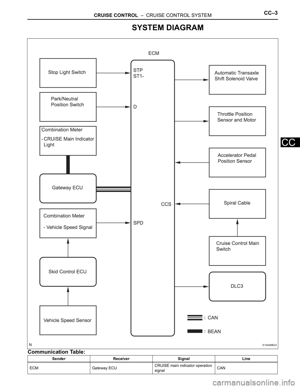
SYSTEM DIAGRAM
Communication Table:
Sender Receiver Signal Line
ECM Gateway ECUCRUISE main indicator operation
signalCAN
E144498E02
Page 246 of 3000

CC–4CRUISE CONTROL – CRUISE CONTROL SYSTEM
CC
Gateway ECU Combination meterCRUISE main indicator operation
signalBEAN Sender Receiver Signal Line
Page 383 of 3000

2GR-FE ENGINE CONTROL SYSTEM – SFI SYSTEMES–77
ES
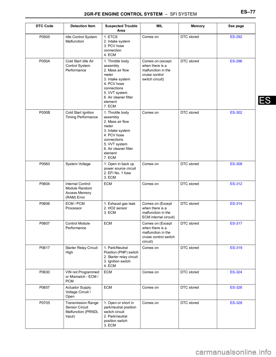
P0505 Idle Control System
Malfunction1. ETCS
2. Intake system
3. PCV hose
connection
4. ECMComes on DTC storedES-292
P050A Cold Start Idle Air
Control System
Performance1. Throttle body
assembly
2. Mass air flow
meter
3. Intake system
4. PCV hose
connections
5. VVT system
6. Air cleaner filter
element
7. ECMComes on (except
when there is a
malfunction in the
cruise control
switch circuit)DTC storedES-296
P050B Cold Start Ignition
Timing Performance1. Throttle body
assembly
2. Mass air flow
meter
3. Intake system
4. PCV hose
connections
5. VVT system
6. Air cleaner filter
element
7. ECMComes on DTC storedES-302
P0560 System Voltage 1. Open in back up
power source circuit
2. EFI No. 1 fuse
3. ECMComes on DTC storedES-308
P0604 Internal Control
Module Random
Access Memory
(RAM) ErrorECM Comes on DTC storedES-312
P0606 ECM / PCM
Processor1. Exhaust gas leak
2. HO2 sensor
3. ECMComes on (Except
when there is a
malfunction in the
ECM internal circuit)DTC storedES-314
P0607 Control Module
PerformanceECM Comes on (Except
when there is a
malfunction in the
cruise control switch
circuit)DTC storedES-317
P0617 Starter Relay Circuit
High1. Park/Neutral
Position (PNP) switch
2. Starter relay circuit
3. Ignition switch
4. ECMComes on DTC storedES-319
P0630 VIN not Programmed
or Mismatch - ECM /
PCMECM Comes on DTC storedES-324
P0657 Actuator Supply
Voltage Circuit /
OpenECM Comes on DTC storedES-326
P0705 Transmission Range
Sensor Circuit
Malfunction (PRNDL
Input)1. Open or short in
park/neutral position
switch circuit
2. Park/neutral
position switch
3. ECMComes on DTC storedES-328 DTC Code Detection Item Suspected Trouble
AreaMIL Memory See page
Page 615 of 3000

ES–3222GR-FE ENGINE CONTROL SYSTEM – SFI SYSTEM
ES
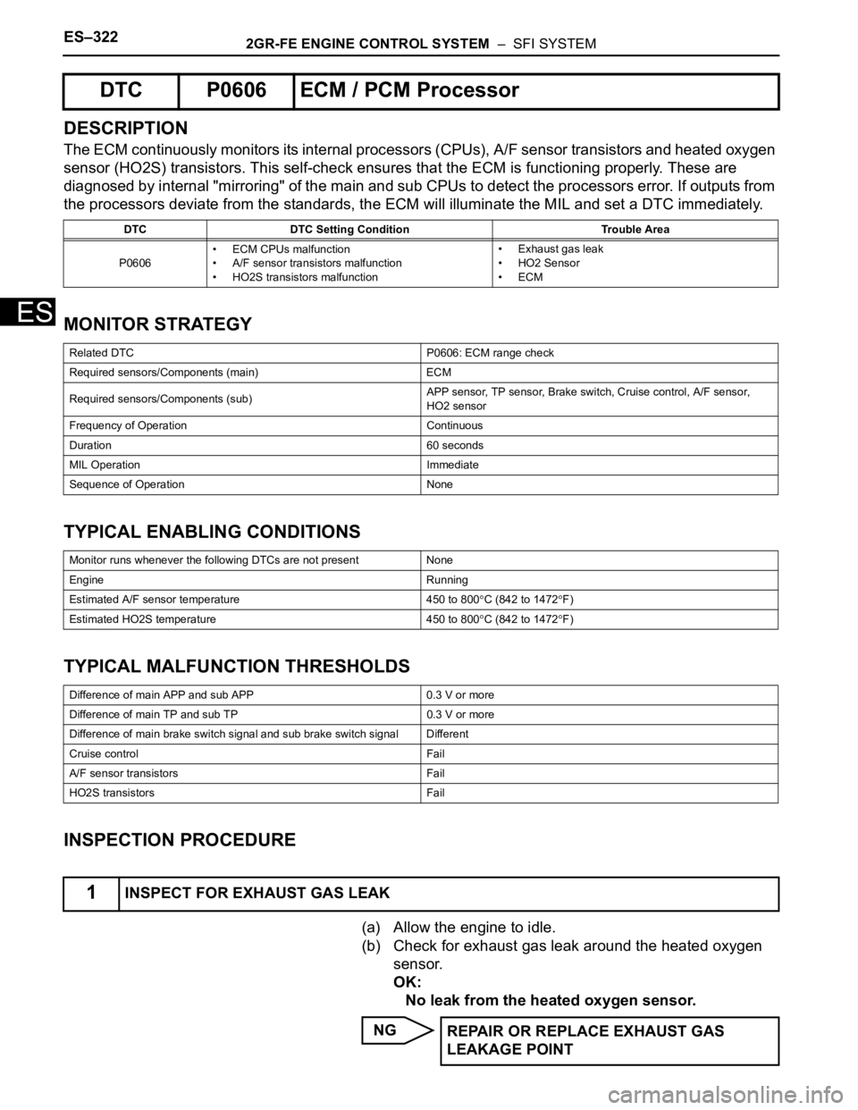
DESCRIPTION
The ECM continuously monitors its internal processors (CPUs), A/F sensor transistors and heated oxygen
sensor (HO2S) transistors. This self-check ensures that the ECM is functioning properly. These are
diagnosed by internal "mirroring" of the main and sub CPUs to detect the processors error. If outputs from
the processors deviate from the standards, the ECM will illuminate the MIL and set a DTC immediately.
MONITOR STRATEGY
TYPICAL ENABLING CONDITIONS
TYPICAL MALFUNCTION THRESHOLDS
INSPECTION PROCEDURE
(a) Allow the engine to idle.
(b) Check for exhaust gas leak around the heated oxygen
sensor.
OK:
No leak from the heated oxygen sensor.
NG
DTC P0606 ECM / PCM Processor
DTC DTC Setting Condition Trouble Area
P0606• ECM CPUs malfunction
• A/F sensor transistors malfunction
• HO2S transistors malfunction• Exhaust gas leak
•HO2 Sensor
•ECM
Related DTC P0606: ECM range check
Required sensors/Components (main) ECM
Required sensors/Components (sub)APP sensor, TP sensor, Brake switch, Cruise control, A/F sensor,
HO2 sensor
Frequency of Operation Continuous
Duration 60 seconds
MIL Operation Immediate
Sequence of Operation None
Monitor runs whenever the following DTCs are not present None
Engine Running
Estimated A/F sensor temperature 450 to 800
C (842 to 1472F)
Estimated HO2S temperature 450 to 800
C (842 to 1472F)
Difference of main APP and sub APP 0.3 V or more
Difference of main TP and sub TP 0.3 V or more
Difference of main brake switch signal and sub brake switch signal Different
Cruise control Fail
A/F sensor transistors Fail
HO2S transistors Fail
1INSPECT FOR EXHAUST GAS LEAK
REPAIR OR REPLACE EXHAUST GAS
LEAKAGE POINT
Page 618 of 3000

2GR-FE ENGINE CONTROL SYSTEM – SFI SYSTEMES–325
ES
DESCRIPTION
The ECM continuously monitors its main and sub CPUs. This self-check ensures that the ECM is
functioning properly. If outputs from the CPUs are different and deviate from the standards, the ECM will
illuminate the MIL and set a DTC immediately.
The ECM also monitors the cruise control cancel circuit. If this circuit malfunctions, the ECM will set a
DTC immediately (MIL is not illuminated).
NOTICE:
First check for an exhaust gas leak around the HO2S if P0606 is present. An exhaust gas leak
generates noise in the HO2S output. The ECM may interpret this as an HO2S transistor
malfunction.
MONITOR STRATEGY
TYPICAL ENABLING CONDITIONS
TYPICAL MALFUNCTION THRESHOLDS
INSPECTION PROCEDURE
(a) Connect the intelligent tester to the DLC3.
(b) Turn the ignition switch to the ON position.
(c) Turn the tester on.
(d) Clear the DTC.
(e) Turn the ignition switch off.
(f) Disconnect the battery negative terminal and wait for 1
minute.
(g) Connect the battery negative terminal.
DTC P0607 Control Module Performance
DTC No. DTC Detection Condition Trouble Area
P0607• ECM main CPU error
• ECM sub CPU error
• Cruise control cancel circuit malfunctionECM
Related DTC P0607: ECM CPU malfunction
Required sensors/Components ECM
Frequency of Operation Continuous
Duration Within 1 second
MIL Operation Immediate
Sequence of Operation None
Monitor runs whenever the following DTCs are not present None
Either of the following conditions is met: Condition A or B
A. All of the following conditions are met: Conditions (a), (b) and (c)
(a) CPU reset 1 time or more
(b) Learned TP - learned APP 0.4 V or more
(c) Throttle actuator OFF
B. CPU reset 2 times or more
1CHECK WHETHER DTC OUTPUT RECURS (IN ADDITION TO DTC P0607)