Page 899 of 3000
EM–942GR-FE ENGINE MECHANICAL – ENGINE UNIT
EM
55. REMOVE INTAKE VALVE
(a) Using SST, compress the inner compression spring
and remove the valve spring retainer locks.
SST 09202-70020 (09202-00010)
(b) Remove the valve spring retainer, inner
compression spring and intake valve.
HINT:
Arrange the removed parts in the correct order.
56. REMOVE EXHAUST VALVE
(a) Using SST, compress the inner compression spring
and remove the valve spring retainer locks.
SST 09202-70020 (09202-00010)
(b) Remove the valve spring retainer, inner
compression spring and exhaust valve.
HINT:
Arrange the removed parts in the correct order.
57. REMOVE VALVE STEM OIL SEAL
(a) Using needle-nose pliers, remove the valve stem oil
seals.
58. REMOVE VALVE SPRING SEAT
(a) Using compressed air and a magnetic finger,
remove the valve spring seats by blowing air onto
them.
A129714E01
A129715E01
A120701E01
A120702E01
Page 948 of 3000
2GR-FE ENGINE MECHANICAL – ENGINE UNITEM–139
EM
17. INSTALL STRAIGHT PIN
(a) Using a plastic hammer, tap in new straight pins as
shown in the illustration.
Protrusion height:
17.5 to 19.5 mm (0.689 to 0.768 in.)
18. INSTALL VALVE SPRING SEAT
(a) Install the valve spring seats to the cylinder head.
19. INSTALL VALVE STEM OIL SEAL
(a) Apply a light coat of engine oil to new valve stem oil
seals.
NOTICE:
Pay attention when installing the intake and
exhaust valve stem oil seals. For example,
installing the intake valve stem oil seal into the
exhaust side or installing the exhaust valve
stem oil seal to the intake side can cause
installation problems later.
HINT:
The intake valve oil seals are gray and the exhaust
valve oil seals are black.
(b) Using SST, push in the oil seals.
SST 09201-41020
NOTICE:
Failure to use SST will cause the seal to be
damaged or improperly seated.
A131890E03
A094934E04
A124592E02
Page 1041 of 3000
EM–942GR-FE ENGINE MECHANICAL – ENGINE UNIT
EM
55. REMOVE INTAKE VALVE
(a) Using SST, compress the inner compression spring
and remove the valve spring retainer locks.
SST 09202-70020 (09202-00010)
(b) Remove the valve spring retainer, inner
compression spring and intake valve.
HINT:
Arrange the removed parts in the correct order.
56. REMOVE EXHAUST VALVE
(a) Using SST, compress the inner compression spring
and remove the valve spring retainer locks.
SST 09202-70020 (09202-00010)
(b) Remove the valve spring retainer, inner
compression spring and exhaust valve.
HINT:
Arrange the removed parts in the correct order.
57. REMOVE VALVE STEM OIL SEAL
(a) Using needle-nose pliers, remove the valve stem oil
seals.
58. REMOVE VALVE SPRING SEAT
(a) Using compressed air and a magnetic finger,
remove the valve spring seats by blowing air onto
them.
A129714E01
A129715E01
A120701E01
A120702E01
Page 1086 of 3000
2GR-FE ENGINE MECHANICAL – ENGINE UNITEM–139
EM
17. INSTALL STRAIGHT PIN
(a) Using a plastic hammer, tap in new straight pins as
shown in the illustration.
Protrusion height:
17.5 to 19.5 mm (0.689 to 0.768 in.)
18. INSTALL VALVE SPRING SEAT
(a) Install the valve spring seats to the cylinder head.
19. INSTALL VALVE STEM OIL SEAL
(a) Apply a light coat of engine oil to new valve stem oil
seals.
NOTICE:
Pay attention when installing the intake and
exhaust valve stem oil seals. For example,
installing the intake valve stem oil seal into the
exhaust side or installing the exhaust valve
stem oil seal to the intake side can cause
installation problems later.
HINT:
The intake valve oil seals are gray and the exhaust
valve oil seals are black.
(b) Using SST, push in the oil seals.
SST 09201-41020
NOTICE:
Failure to use SST will cause the seal to be
damaged or improperly seated.
A131890E03
A094934E04
A124592E02
Page 2187 of 3000

SUSPENSION – FRONT WHEEL ALIGNMENTSP–5
SP
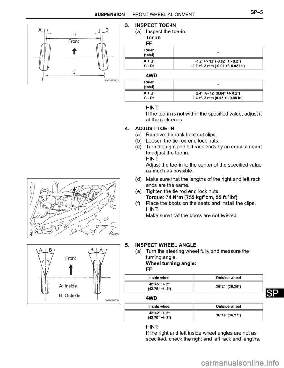
3. INSPECT TOE-IN
(a) Inspect the toe-in.
To e - i n
FF
4WD
HINT:
If the toe-in is not within the specified value, adjust it
at the rack ends.
4. ADJUST TOE-IN
(a) Remove the rack boot set clips.
(b) Loosen the tie rod end lock nuts.
(c) Turn the right and left rack ends by an equal amount
to adjust the toe-in.
HINT:
Adjust the toe-in to the center of the specified value
as much as possible.
(d) Make sure that the lengths of the right and left rack
ends are the same.
(e) Tighten the tie rod end lock nuts.
Torque: 74 N*m (755 kgf*cm, 55 ft.*lbf)
(f) Place the boots on the seats and install the clips.
HINT:
Make sure that the boots are not twisted.
5. INSPECT WHEEL ANGLE
(a) Turn the steering wheel fully and measure the
turning angle.
Wheel turning angle:
FF
4WD
HINT:
If the right and left inside wheel angles are not as
specified, check the right and left rack end lengths.
SA03213E12
To e - i n
(total)-
A + B:
C - D:-1.2' +/- 12' (-0.02
+/- 0.2)
-0.2 +/- 2 mm (-0.01 +/- 0.08 in.)
To e - i n
(total)-
A + B:
C - D:2.4' +/- 12' (0.04
+/- 0.2)
0.4 +/- 2 mm (0.02 +/- 0.08 in.)
F040165
SA00028E10
Inside wheel Outside wheel
42
45' +/- 2(42.75 +/- 2)3621' (36.35)
Inside wheel Outside wheel
42
42' +/- 2
(42.70 +/- 2)3616' (36.27)