Page 189 of 3000

STEERING COLUMN – STEERING SYSTEMSR–3
SR
REPAIR
1. STEERING OFF CENTER REPAIR PROCEDURE
(a) Inspect steering wheel off center.
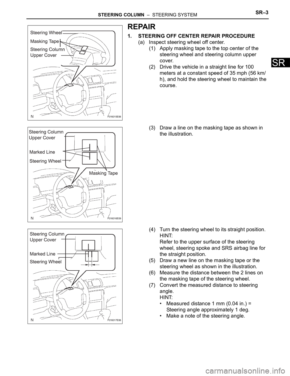
(1) Apply masking tape to the top center of the
steering wheel and steering column upper
cover.
(2) Drive the vehicle in a straight line for 100
meters at a constant speed of 35 mph (56 km/
h), and hold the steering wheel to maintain the
course.
(3) Draw a line on the masking tape as shown in
the illustration.
(4) Turn the steering wheel to its straight position.
HINT:
Refer to the upper surface of the steering
wheel, steering spoke and SRS airbag line for
the straight position.
(5) Draw a new line on the masking tape or the
steering wheel as shown in the illustration.
(6) Measure the distance between the 2 lines on
the masking tape of the steering wheel.
(7) Convert the measured distance to steering
angle.
HINT:
• Measured distance 1 mm (0.04 in.) =
Steering angle approximately 1 deg.
• Make a note of the steering angle.
F016015E06
F016016E09
F016017E06
Page 233 of 3000

SUPPLEMENTAL RESTRAINT SYSTEM – SIDE AIRBAG SENSORRS–475
RS
INSTALLATION
HINT:
• Use the same procedures for the RH side and LH side.
• The procedures listed below are for the LH side.
1. INSTALL SIDE AIRBAG SENSOR LH
(a) Check that the ignition switch is off.
(b) Check that the battery negative (-) terminal is
disconnected.
CAUTION:
After disconnecting the negative battery
terminal, wait for at least 90 seconds before
starting the operation.
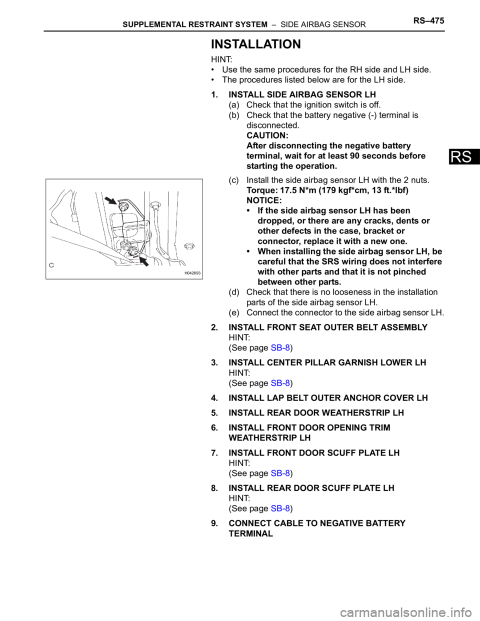
(c) Install the side airbag sensor LH with the 2 nuts.
Torque: 17.5 N*m (179 kgf*cm, 13 ft.*lbf)
NOTICE:
• If the side airbag sensor LH has been
dropped, or there are any cracks, dents or
other defects in the case, bracket or
connector, replace it with a new one.
• When installing the side airbag sensor LH, be
careful that the SRS wiring does not interfere
with other parts and that it is not pinched
between other parts.
(d) Check that there is no looseness in the installation
parts of the side airbag sensor LH.
(e) Connect the connector to the side airbag sensor LH.
2. INSTALL FRONT SEAT OUTER BELT ASSEMBLY
HINT:
(See page SB-8)
3. INSTALL CENTER PILLAR GARNISH LOWER LH
HINT:
(See page SB-8)
4. INSTALL LAP BELT OUTER ANCHOR COVER LH
5. INSTALL REAR DOOR WEATHERSTRIP LH
6. INSTALL FRONT DOOR OPENING TRIM
WEATHERSTRIP LH
7. INSTALL FRONT DOOR SCUFF PLATE LH
HINT:
(See page SB-8)
8. INSTALL REAR DOOR SCUFF PLATE LH
HINT:
(See page SB-8)
9. CONNECT CABLE TO NEGATIVE BATTERY
TERMINAL
H042693
Page 2995 of 3000
RS–18SUPPLEMENTAL RESTRAINT SYSTEM – AIRBAG SYSTEM
RS
(5) Diagnostic circuit
• This circuit constantly diagnoses system
malfunctions. When a malfunction is
detected, it lights up the SRS warning light on
the combination meter assembly to inform the
driver.
(6) Memory circuit
• When a malfunction is detected in the
diagnostic circuit, it is coded and stored in the
memory circuit.
(e) SRS WARNING LIGHT
(1) The SRS warning light is located on the
combination meter assembly. It comes on to
inform the driver of system trouble when a
malfunction is detected in self-diagnosis of the
center airbag sensor assembly. Under normal
operating conditions, when the ignition switch is
turned to the ON position, it comes on for
approximately 6 seconds and then goes off.