2007 TOYOTA SIENNA regulator
[x] Cancel search: regulatorPage 59 of 3000

IN–52INTRODUCTION – TERMS
IN
TWC+OC Three-Way + Oxidation Catalytic ConverterCCR + CCo
VAF Volume Airflow Air Flow Meter
VR Voltage Regulator Voltage Regulator
VSS Vehicle Speed Sensor Vehicle Speed Sensor
WOT Wide Open Throttle Full Throttle
WU-OC Warm Up Oxidation Catalytic Converter -
WU-TWC Warm Up Three-Way Catalytic Converter -
3GR Third Gear -
4GR Fourth Gear -SAE
ABBREVIATIONSSAE TERMSTOYOTA TERMS
( )-ABBREVIATIONS
Page 282 of 3000

WINDSHIELD / WINDOWGLASS – POWER WINDOW CONTROL SYSTEM (w/ Jam Protec-
tion Function)WS–7
WS
INITIALIZATION
NOTICE:
• Resetting the power window motor (initializing the
pulse sensor) is necessary when the battery terminal
is disconnected; when the master switch, wire
harness, power window regulator and power window
motor are replaced or removed/installed; or when the
fuses are replaced. AUTO operation function, jam
protection function and remote operation function via
the power window master switch do not operate
without resetting.
• If the AUTO switch (driver side switch) of the master
switch has been continuously operated for a long
time, the power window motor will stop so that no
additional load can be applied to the motor.
Continuing to operate the switch even after the motor
has stopped will cause the switch to blink while
restricting the AUTO UP/DOWN function and the
remote UP/DOWN function. If this happens, reset the
motor again after several minutes have passed.
• Whenever disconnecting the battery terminal, reset all
the other systems besides the power window control
system.
1. RESET POWER WINDOW REGULATOR MOTOR
(DRIVER SIDE)
(a) Turn the ignition switch ON.
(b) Halfway open the power window by pressing the
power window switch.
(c) Fully pull up the switch until the power window is
fully closed and continue to hold the switch for
approx. 1 second after the power window is fully
closed.
(d) Check that the AUTO UP/DOWN function operates
normally.
If the AUTO UP/DOWN function operates normally,
reset operations have been completed at this time.
If not normal, follow steps below.
(1) Disconnect the negative battery terminal for 10
seconds.
(2) Connect the battery terminal.
(3) Perform the above steps (a) to (d) again.
HINT:
If operation is normal, reset operations have
been completed at this time. If not normal, follow
steps (4) to (7).
(4) Turn the ignition switch ON.
(5) Halfway open the power window by pressing the
power window switch.
(6) Fully pull up the switch until the power window is
fully closed and continue to hold the switch for
approx. 12 seconds after the power window is
fully closed.
(7) Check that the AUTO UP/DOWN function
operates normally.
Page 520 of 3000
ES–2142GR-FE ENGINE CONTROL SYSTEM – SFI SYSTEM
ES
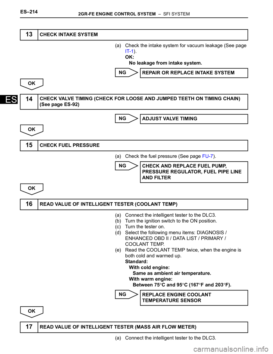
(a) Check the intake system for vacuum leakage (See page
IT-1).
OK:
No leakage from intake system.
NG
OK
NG
OK
(a) Check the fuel pressure (See page FU-7).
NG
OK
(a) Connect the intelligent tester to the DLC3.
(b) Turn the ignition switch to the ON position.
(c) Turn the tester on.
(d) Select the following menu items: DIAGNOSIS /
ENHANCED OBD II / DATA LIST / PRIMARY /
COOLANT TEMP.
(e) Read the COOLANT TEMP twice, when the engine is
both cold and warmed up.
Standard:
With cold engine:
Same as ambient air temperature.
With warm engine:
Between 75
C and 95C (167F and 203F).
NG
OK
(a) Connect the intelligent tester to the DLC3.
13CHECK INTAKE SYSTEM
REPAIR OR REPLACE INTAKE SYSTEM
14CHECK VALVE TIMING (CHECK FOR LOOSE AND JUMPED TEETH ON TIMING CHAIN)
(See page ES-92)
ADJUST VALVE TIMING
15CHECK FUEL PRESSURE
CHECK AND REPLACE FUEL PUMP,
PRESSURE REGULATOR, FUEL PIPE LINE
AND FILTER
16READ VALUE OF INTELLIGENT TESTER (COOLANT TEMP)
REPLACE ENGINE COOLANT
TEMPERATURE SENSOR
17READ VALUE OF INTELLIGENT TESTER (MASS AIR FLOW METER)
Page 521 of 3000
2GR-FE ENGINE CONTROL SYSTEM – SFI SYSTEMES–215
ES
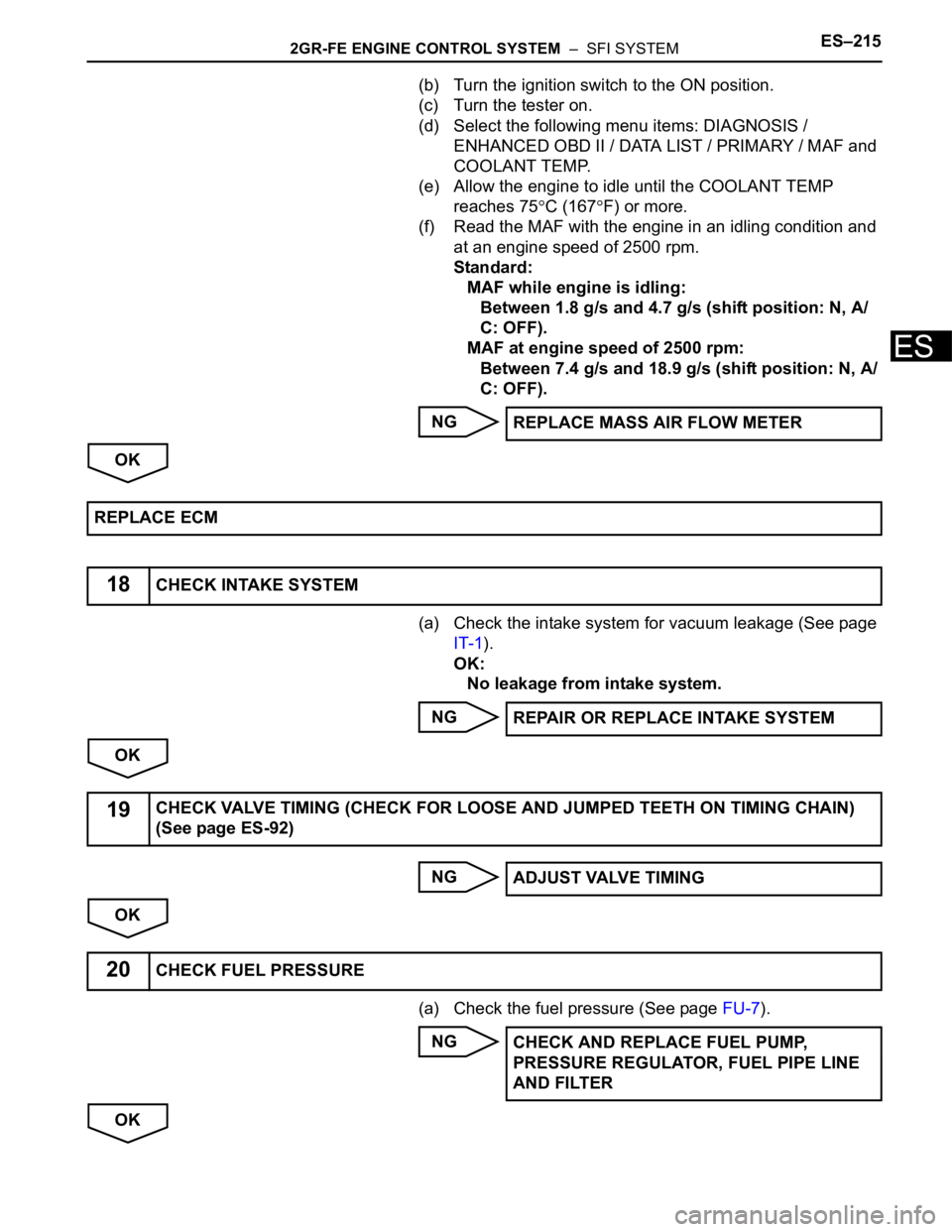
(b) Turn the ignition switch to the ON position.
(c) Turn the tester on.
(d) Select the following menu items: DIAGNOSIS /
ENHANCED OBD II / DATA LIST / PRIMARY / MAF and
COOLANT TEMP.
(e) Allow the engine to idle until the COOLANT TEMP
reaches 75
C (167F) or more.
(f) Read the MAF with the engine in an idling condition and
at an engine speed of 2500 rpm.
Standard:
MAF while engine is idling:
Between 1.8 g/s and 4.7 g/s (shift position: N, A/
C: OFF).
MAF at engine speed of 2500 rpm:
Between 7.4 g/s and 18.9 g/s (shift position: N, A/
C: OFF).
NG
OK
(a) Check the intake system for vacuum leakage (See page
IT-1).
OK:
No leakage from intake system.
NG
OK
NG
OK
(a) Check the fuel pressure (See page FU-7).
NG
OKREPLACE MASS AIR FLOW METER
REPLACE ECM
18CHECK INTAKE SYSTEM
REPAIR OR REPLACE INTAKE SYSTEM
19CHECK VALVE TIMING (CHECK FOR LOOSE AND JUMPED TEETH ON TIMING CHAIN)
(See page ES-92)
ADJUST VALVE TIMING
20CHECK FUEL PRESSURE
CHECK AND REPLACE FUEL PUMP,
PRESSURE REGULATOR, FUEL PIPE LINE
AND FILTER
Page 934 of 3000
EM–42GR-FE ENGINE MECHANICAL – ENGINE
EM
(h) Install the 6 ignition coils.
Torque: 10 N*m (102 kgf*cm, 7 ft.*lbf)
(i) Install the intake air surge tank (See page ES-522).
10. INSPECT CO/HC
(a) Start the engine.
(b) Run the engine at 2500 rpm for approximately 180
seconds.
(c) Insert the CO/HC meter testing probe at least 40 cm
(1.3 ft.) into the tailpipe during idling.
(d) Check CO/HC concentration at idle and/or 2500
rpm.
HINT:
Check regulations and restrictions in your area
when performing 2 mode CO/HC concentration
testing (engine check at both idle speed and at 2500
rpm).
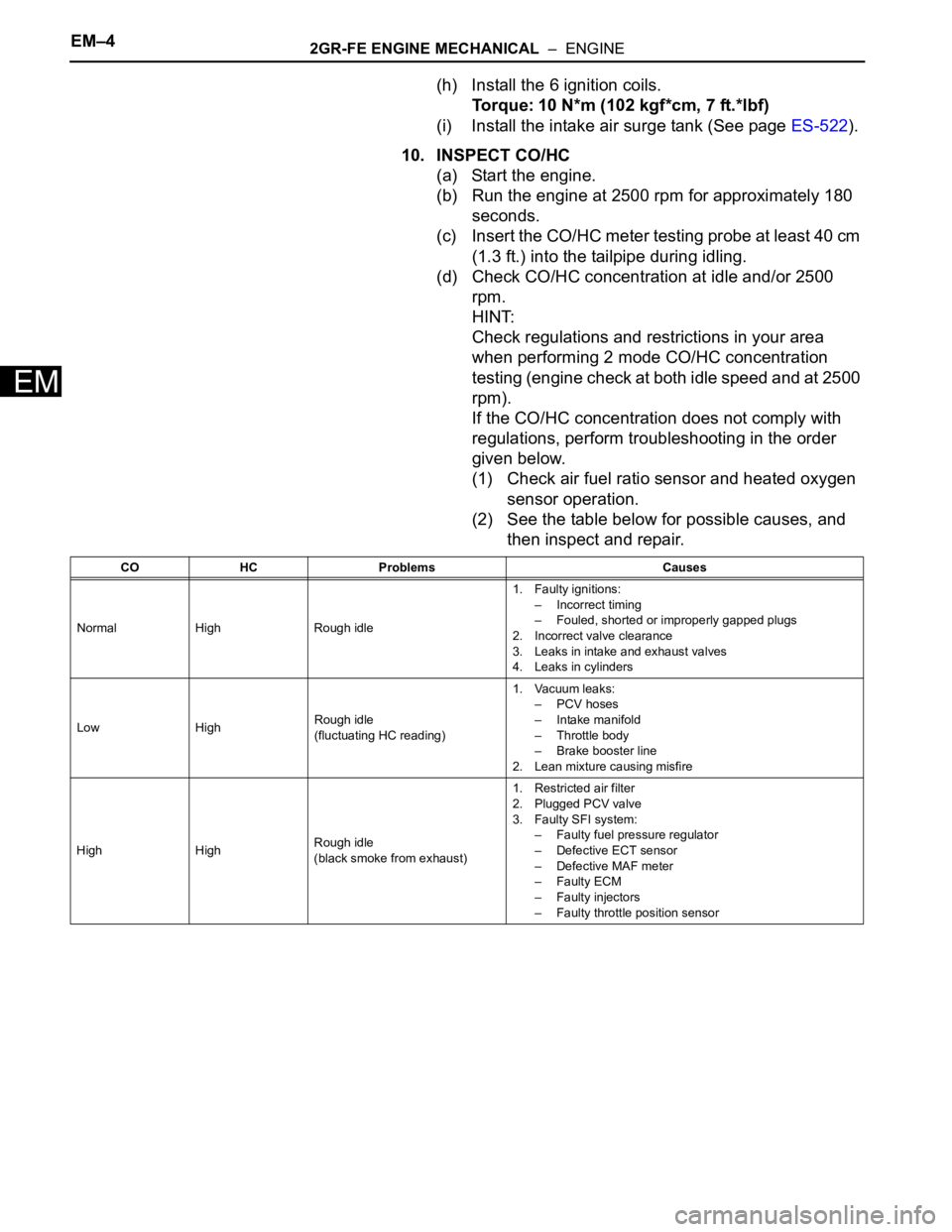
If the CO/HC concentration does not comply with
regulations, perform troubleshooting in the order
given below.
(1) Check air fuel ratio sensor and heated oxygen
sensor operation.
(2) See the table below for possible causes, and
then inspect and repair.
CO HC Problems Causes
Normal High Rough idle1. Faulty ignitions:
– Incorrect timing
– Fouled, shorted or improperly gapped plugs
2. Incorrect valve clearance
3. Leaks in intake and exhaust valves
4. Leaks in cylinders
Low HighRough idle
(fluctuating HC reading)1. Vacuum leaks:
– PCV hoses
– Intake manifold
– Throttle body
– Brake booster line
2. Lean mixture causing misfire
High HighRough idle
(black smoke from exhaust)1. Restricted air filter
2. Plugged PCV valve
3. Faulty SFI system:
– Faulty fuel pressure regulator
– Defective ECT sensor
– Defective MAF meter
–Faulty ECM
– Faulty injectors
– Faulty throttle position sensor
Page 1118 of 3000
FU–82GR-FE FUEL – FUEL SYSTEM
FU
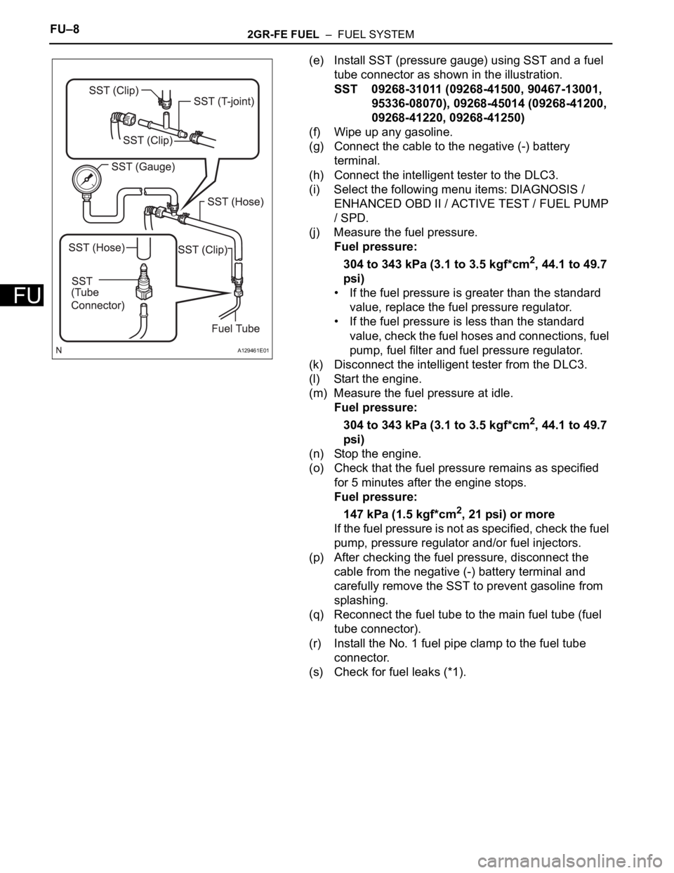
(e) Install SST (pressure gauge) using SST and a fuel
tube connector as shown in the illustration.
SST 09268-31011 (09268-41500, 90467-13001,
95336-08070), 09268-45014 (09268-41200,
09268-41220, 09268-41250)
(f) Wipe up any gasoline.
(g) Connect the cable to the negative (-) battery
terminal.
(h) Connect the intelligent tester to the DLC3.
(i) Select the following menu items: DIAGNOSIS /
ENHANCED OBD II / ACTIVE TEST / FUEL PUMP
/ SPD.
(j) Measure the fuel pressure.
Fuel pressure:
304 to 343 kPa (3.1 to 3.5 kgf*cm
2, 44.1 to 49.7
psi)
• If the fuel pressure is greater than the standard
value, replace the fuel pressure regulator.
• If the fuel pressure is less than the standard
value, check the fuel hoses and connections, fuel
pump, fuel filter and fuel pressure regulator.
(k) Disconnect the intelligent tester from the DLC3.
(l) Start the engine.
(m) Measure the fuel pressure at idle.
Fuel pressure:
304 to 343 kPa (3.1 to 3.5 kgf*cm
2, 44.1 to 49.7
psi)
(n) Stop the engine.
(o) Check that the fuel pressure remains as specified
for 5 minutes after the engine stops.
Fuel pressure:
147 kPa (1.5 kgf*cm
2, 21 psi) or more
If the fuel pressure is not as specified, check the fuel
pump, pressure regulator and/or fuel injectors.
(p) After checking the fuel pressure, disconnect the
cable from the negative (-) battery terminal and
carefully remove the SST to prevent gasoline from
splashing.
(q) Reconnect the fuel tube to the main fuel tube (fuel
tube connector).
(r) Install the No. 1 fuel pipe clamp to the fuel tube
connector.
(s) Check for fuel leaks (*1).
A129461E01
Page 1127 of 3000
FU–82GR-FE FUEL – FUEL SYSTEM
FU
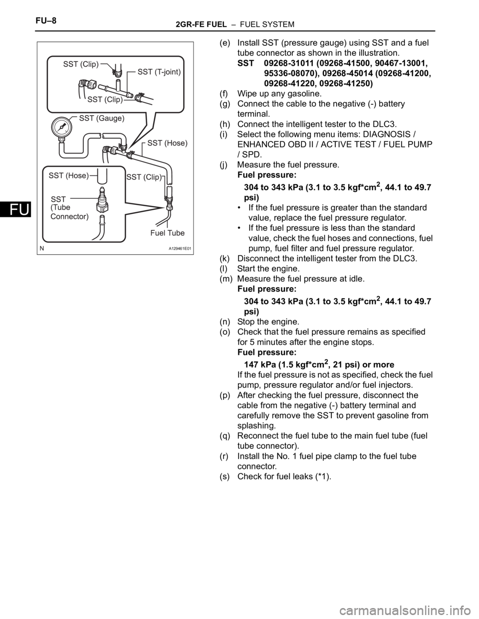
(e) Install SST (pressure gauge) using SST and a fuel
tube connector as shown in the illustration.
SST 09268-31011 (09268-41500, 90467-13001,
95336-08070), 09268-45014 (09268-41200,
09268-41220, 09268-41250)
(f) Wipe up any gasoline.
(g) Connect the cable to the negative (-) battery
terminal.
(h) Connect the intelligent tester to the DLC3.
(i) Select the following menu items: DIAGNOSIS /
ENHANCED OBD II / ACTIVE TEST / FUEL PUMP
/ SPD.
(j) Measure the fuel pressure.
Fuel pressure:
304 to 343 kPa (3.1 to 3.5 kgf*cm
2, 44.1 to 49.7
psi)
• If the fuel pressure is greater than the standard
value, replace the fuel pressure regulator.
• If the fuel pressure is less than the standard
value, check the fuel hoses and connections, fuel
pump, fuel filter and fuel pressure regulator.
(k) Disconnect the intelligent tester from the DLC3.
(l) Start the engine.
(m) Measure the fuel pressure at idle.
Fuel pressure:
304 to 343 kPa (3.1 to 3.5 kgf*cm
2, 44.1 to 49.7
psi)
(n) Stop the engine.
(o) Check that the fuel pressure remains as specified
for 5 minutes after the engine stops.
Fuel pressure:
147 kPa (1.5 kgf*cm
2, 21 psi) or more
If the fuel pressure is not as specified, check the fuel
pump, pressure regulator and/or fuel injectors.
(p) After checking the fuel pressure, disconnect the
cable from the negative (-) battery terminal and
carefully remove the SST to prevent gasoline from
splashing.
(q) Reconnect the fuel tube to the main fuel tube (fuel
tube connector).
(r) Install the No. 1 fuel pipe clamp to the fuel tube
connector.
(s) Check for fuel leaks (*1).
A129461E01
Page 1151 of 3000
2GR-FE FUEL – FUEL PUMPFU–33
FU
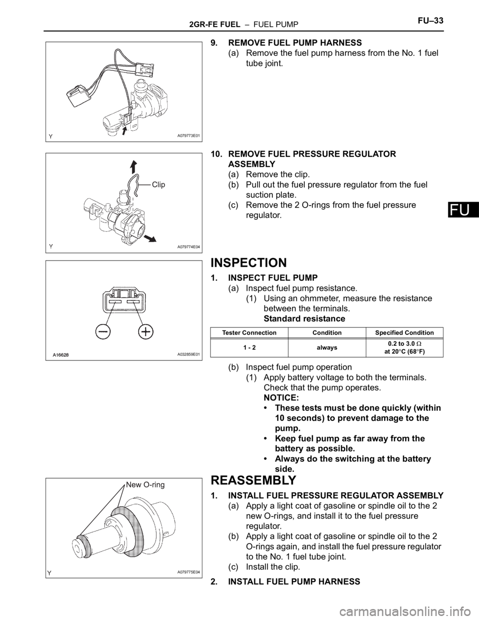
9. REMOVE FUEL PUMP HARNESS
(a) Remove the fuel pump harness from the No. 1 fuel
tube joint.
10. REMOVE FUEL PRESSURE REGULATOR
ASSEMBLY
(a) Remove the clip.
(b) Pull out the fuel pressure regulator from the fuel
suction plate.
(c) Remove the 2 O-rings from the fuel pressure
regulator.
INSPECTION
1. INSPECT FUEL PUMP
(a) Inspect fuel pump resistance.
(1) Using an ohmmeter, measure the resistance
between the terminals.
Standard resistance
(b) Inspect fuel pump operation
(1) Apply battery voltage to both the terminals.
Check that the pump operates.
NOTICE:
• These tests must be done quickly (within
10 seconds) to prevent damage to the
pump.
• Keep fuel pump as far away from the
battery as possible.
• Always do the switching at the battery
side.
REASSEMBLY
1. INSTALL FUEL PRESSURE REGULATOR ASSEMBLY
(a) Apply a light coat of gasoline or spindle oil to the 2
new O-rings, and install it to the fuel pressure
regulator.
(b) Apply a light coat of gasoline or spindle oil to the 2
O-rings again, and install the fuel pressure regulator
to the No. 1 fuel tube joint.
(c) Install the clip.
2. INSTALL FUEL PUMP HARNESS
A079773E01
A079774E04
A032859E01
Tester Connection Condition Specified Condition
1 - 2 always0.2 to 3.0
at 20
C (68F)
A079775E04