Page 38 of 3000
2GR-FE ENGINE MECHANICAL – ENGINE ASSEMBLYEM–39
EM
83. REMOVE NO. 2 ENGINE MOUNTING STAY RH
(a) Remove the bolt and No. 2 engine mounting stay
RH.
84. REMOVE INTAKE MANIFOLD
(a) Uniformly loosen and remove the 6 bolts and 4 nuts.
(b) Remove the intake manifold and 2 gaskets.
85. REMOVE EXHAUST MANIFOLD SUB-ASSEMBLY RH
(a) Disconnect the A/F sensor connector clamp.
(b) Uniformly loosen and remove the 6 nuts.
(c) Remove the manifold and gasket.
86. REMOVE OIL LEVEL GAUGE GUIDE SUB-
ASSEMBLY
(a) Remove the oil level gauge.
(b) Remove the 2 bolts, No. 1 and No. 2 oil level gauge
guides.
(c) Remove the O-rings from the oil level gauge guide.
87. REMOVE NO. 2 MANIFOLD STAY
(a) Remove the bolt, nut and No. 2 manifold stay.
A162388
A134933
A140781
A155017
A140783
Page 78 of 3000
2GR-FE LUBRICATION – OIL PUMPLU–11
LU
REMOVAL
1. REMOVE ENGINE ASSEMBLY WITH TRANSAXLE
HINT:
See page EM-26
2. REMOVE OIL LEVEL GAUGE GUIDE SUB-
ASSEMBLY (See page EM-39)
3. REMOVE NO. 1 OIL PIPE (See page EM-77)
4. REMOVE OIL PIPE (See page EM-77)
5. REMOVE CRANKSHAFT PULLEY (See page EM-79)
6. SEPARATE OIL COOLER PIPE
(a) Remove the bolt and 2 nuts, and disconnect the oil
cooler pipe from the oil pan sub-assembly.
(b) Remove the gasket from the oil pan sub-assembly.
7. REMOVE WATER INLET HOUSING (See page CO-12)
8. REMOVE CYLINDER HEAD COVER SUB-ASSEMBLY
(for Bank 1) (See page EM-82)
9. REMOVE CYLINDER HEAD COVER SUB-ASSEMBLY
(for Bank 2) (See page EM-82)
10. REMOVE NO. 2 OIL PAN SUB-ASSEMBLY (See page
EM-82)
11. REMOVE OIL STRAINER SUB-ASSEMBLY (See page
EM-83)
12. REMOVE OIL PAN SUB-ASSEMBLY (See page EM-
83)
13. REMOVE TIMING CHAIN COVER SUB-ASSEMBLY
(a) Remove the 23 bolts and 2 nuts as shown in the
illustration.
A141494
A128004
Page 91 of 3000
AX–164U151E AUTOMATIC TRANSAXLE – AUTOMATIC TRANSAXLE ASSEMBLY
AX
7. REMOVE STARTER ASSEMBLY
(a) Disconnect the connector (1).
(b) Remove the nut (2) and disconnect the starter wire.
(c) Remove the 2 bolts (3) and starter assembly.
8. DISCONNECT CONNECTORS
(a) Disconnect the transmission wire connector.
(b) Disconnect the park/neutral position switch
connector.
(c) Disconnect the 2 speed sensor connectors.
9. REMOVE TRANSMISSION CONTROL CABLE
BRACKET NO.1
(a) Remove the bolt and automatic transmission oil
cooler tube clamp.
(b) Remove the 2 bolts and transmission control cable
bracket No.1.
10. REMOVE TRANSMISSION OIL FILLER TUBE SUB-
ASSEMBLY
(a) Remove the ATF level gauge.
(b) Disconnect the wire harnesses 2 clamps from the oil
filler tube.
(c) Remove the 2 bolts and oil filler tube.
(d) Remove the O-ring from the oil filler tube.
D030464E02
D030864E04
D030467
D030468
Page 94 of 3000

U151E AUTOMATIC TRANSAXLE – AUTOMATIC TRANSAXLE ASSEMBLYAX–167
AX
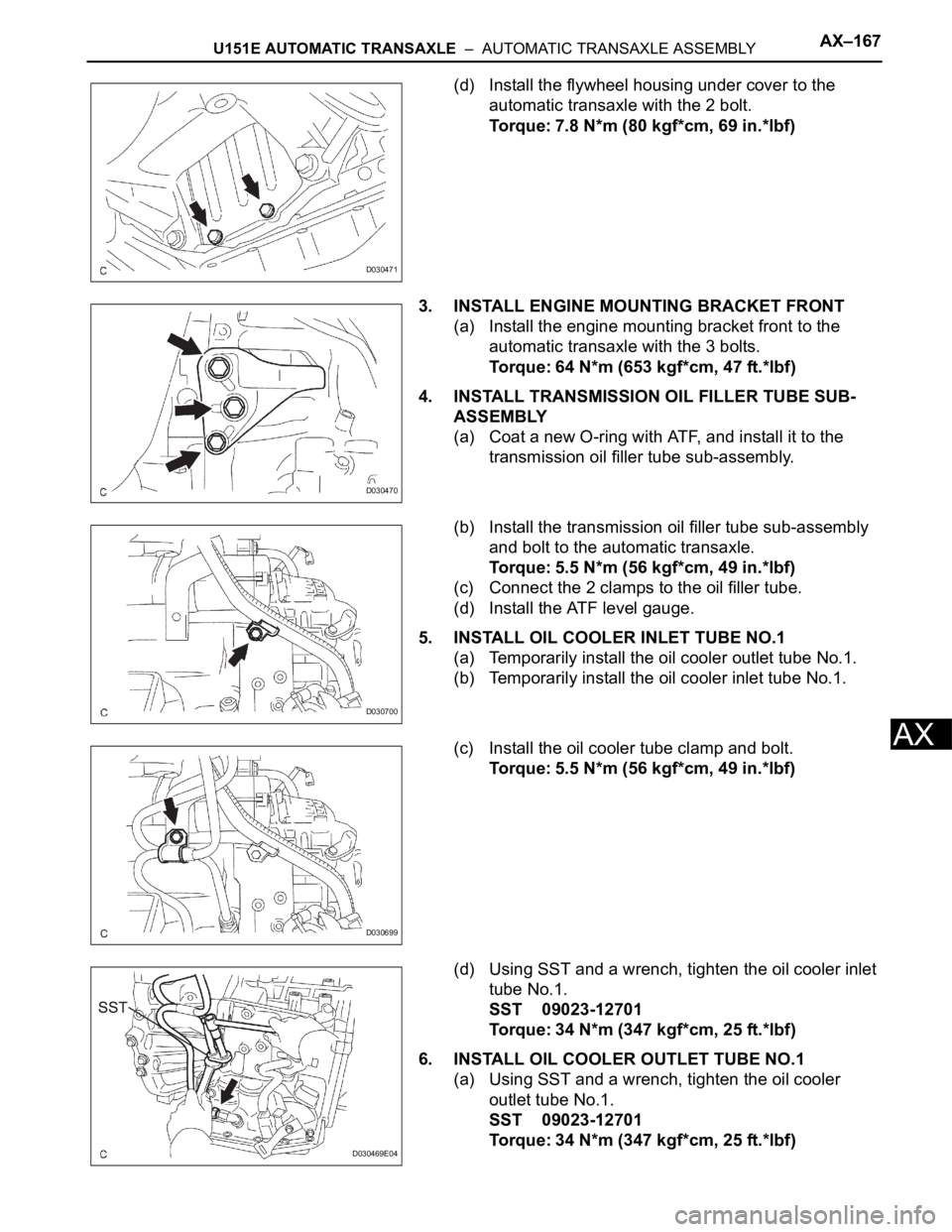
(d) Install the flywheel housing under cover to the
automatic transaxle with the 2 bolt.
Torque: 7.8 N*m (80 kgf*cm, 69 in.*lbf)
3. INSTALL ENGINE MOUNTING BRACKET FRONT
(a) Install the engine mounting bracket front to the
automatic transaxle with the 3 bolts.
Torque: 64 N*m (653 kgf*cm, 47 ft.*lbf)
4. INSTALL TRANSMISSION OIL FILLER TUBE SUB-
ASSEMBLY
(a) Coat a new O-ring with ATF, and install it to the
transmission oil filler tube sub-assembly.
(b) Install the transmission oil filler tube sub-assembly
and bolt to the automatic transaxle.
Torque: 5.5 N*m (56 kgf*cm, 49 in.*lbf)
(c) Connect the 2 clamps to the oil filler tube.
(d) Install the ATF level gauge.
5. INSTALL OIL COOLER INLET TUBE NO.1
(a) Temporarily install the oil cooler outlet tube No.1.
(b) Temporarily install the oil cooler inlet tube No.1.
(c) Install the oil cooler tube clamp and bolt.
Torque: 5.5 N*m (56 kgf*cm, 49 in.*lbf)
(d) Using SST and a wrench, tighten the oil cooler inlet
tube No.1.
SST 09023-12701
Torque: 34 N*m (347 kgf*cm, 25 ft.*lbf)
6. INSTALL OIL COOLER OUTLET TUBE NO.1
(a) Using SST and a wrench, tighten the oil cooler
outlet tube No.1.
SST 09023-12701
Torque: 34 N*m (347 kgf*cm, 25 ft.*lbf)
D030471
D030470
D030700
D030699
D030469E04
Page 100 of 3000
U151F AUTOMATIC TRANSAXLE – AUTOMATIC TRANSAXLE ASSEMBLYAX–165
AX
7. REMOVE STARTER ASSEMBLY
(a) Disconnect the connector (1).
(b) Remove the nut (2) and disconnect the starter wire.
(c) Remove the 2 bolts (3) and starter assembly.
8. DISCONNECT CONNECTORS
(a) Disconnect the transmission wire connector.
(b) Disconnect the park/neutral position switch
connector.
(c) Disconnect the 2 speed sensor connectors.
9. REMOVE TRANSMISSION CONTROL CABLE
BRACKET NO.1
(a) Remove the bolt and automatic transmission oil
cooler tube clamp.
(b) Remove the 2 bolts and transmission control cable
bracket No.1.
10. REMOVE TRANSMISSION OIL FILLER TUBE SUB-
ASSEMBLY
(a) Remove the ATF level gauge.
(b) Disconnect the wire harnesses 2 clamps from the oil
filler tube.
(c) Remove the 2 bolts and oil filler tube.
(d) Remove the O-ring from the oil filler tube.
D030464E02
D030864E04
D030467
D030468
Page 104 of 3000

U151F AUTOMATIC TRANSAXLE – AUTOMATIC TRANSAXLE ASSEMBLYAX–169
AX
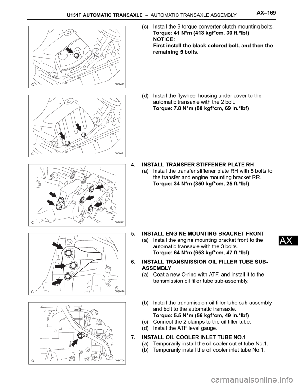
(c) Install the 6 torque converter clutch mounting bolts.
Torque: 41 N*m (413 kgf*cm, 30 ft.*lbf)
NOTICE:
First install the black colored bolt, and then the
remaining 5 bolts.
(d) Install the flywheel housing under cover to the
automatic transaxle with the 2 bolt.
Torque: 7.8 N*m (80 kgf*cm, 69 in.*lbf)
4. INSTALL TRANSFER STIFFENER PLATE RH
(a) Install the transfer stiffener plate RH with 5 bolts to
the transfer and engine mounting bracket RR.
Torque: 34 N*m (350 kgf*cm, 25 ft.*lbf)
5. INSTALL ENGINE MOUNTING BRACKET FRONT
(a) Install the engine mounting bracket front to the
automatic transaxle with the 3 bolts.
Torque: 64 N*m (653 kgf*cm, 47 ft.*lbf)
6. INSTALL TRANSMISSION OIL FILLER TUBE SUB-
ASSEMBLY
(a) Coat a new O-ring with ATF, and install it to the
transmission oil filler tube sub-assembly.
(b) Install the transmission oil filler tube sub-assembly
and bolt to the automatic transaxle.
Torque: 5.5 N*m (56 kgf*cm, 49 in.*lbf)
(c) Connect the 2 clamps to the oil filler tube.
(d) Install the ATF level gauge.
7. INSTALL OIL COOLER INLET TUBE NO.1
(a) Temporarily install the oil cooler outlet tube No.1.
(b) Temporarily install the oil cooler inlet tube No.1.
D030472
D030471
D030512
D030470
D030700
Page 112 of 3000

DRIVE SHAFT – FRONT DRIVE SHAFTDS–7
DS
12. REMOVE FRONT DRIVE SHAFT ASSEMBLY RH (for
4WD)
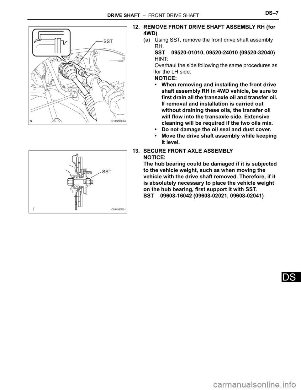
(a) Using SST, remove the front drive shaft assembly
RH.
SST 09520-01010, 09520-24010 (09520-32040)
HINT:
Overhaul the side following the same procedures as
for the LH side.
NOTICE:
• When removing and installing the front drive
shaft assembly RH in 4WD vehicle, be sure to
first drain all the transaxle oil and transfer oil.
If removal and installation is carried out
without draining these oils, the transfer oil
will flow into the transaxle side. Extensive
cleaning will be required if the two oils mix.
• Do not damage the oil seal and dust cover.
• Move the drive shaft assembly while keeping
it level.
13. SECURE FRONT AXLE ASSEMBLY
NOTICE:
The hub bearing could be damaged if it is subjected
to the vehicle weight, such as when moving the
vehicle with the drive shaft removed. Therefore, if it
is absolutely necessary to place the vehicle weight
on the hub bearing, first support it with SST.
SST 09608-16042 (09608-02021, 09608-02041)
C108268E04
C054583E01
Page 197 of 3000

SS–10SERVICE SPECIFICATIONS – 2GR-FE ENGINE MECHANICAL
SS
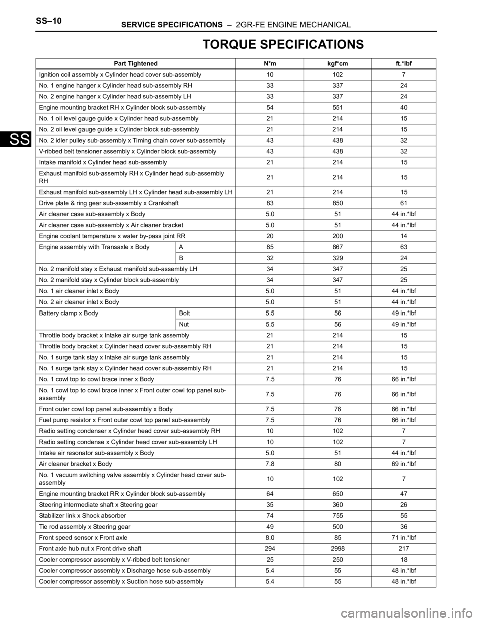
TORQUE SPECIFICATIONS
Part Tightened N*m kgf*cm ft.*lbf
Ignition coil assembly x Cylinder head cover sub-assembly 10 102 7
No. 1 engine hanger x Cylinder head sub-assembly RH 33 337 24
No. 2 engine hanger x Cylinder head sub-assembly LH 33 337 24
Engine mounting bracket RH x Cylinder block sub-assembly 54 551 40
No. 1 oil level gauge guide x Cylinder head sub-assembly 21 214 15
No. 2 oil level gauge guide x Cylinder block sub-assembly 21 214 15
No. 2 idler pulley sub-assembly x Timing chain cover sub-assembly 43 438 32
V-ribbed belt tensioner assembly x Cylinder block sub-assembly 43 438 32
Intake manifold x Cylinder head sub-assembly 21 214 15
Exhaust manifold sub-assembly RH x Cylinder head sub-assembly
RH21 214 15
Exhaust manifold sub-assembly LH x Cylinder head sub-assembly LH 21 214 15
Drive plate & ring gear sub-assembly x Crankshaft 83 850 61
Air cleaner case sub-assembly x Body 5.0 51 44 in.*lbf
Air cleaner case sub-assembly x Air cleaner bracket 5.0 51 44 in.*lbf
Engine coolant temperature x water by-pass joint RR 20 200 14
Engine assembly with Transaxle x Body A 85 867 63
B 32 329 24
No. 2 manifold stay x Exhaust manifold sub-assembly LH 34 347 25
No. 2 manifold stay x Cylinder block sub-assembly 34 347 25
No. 1 air cleaner inlet x Body 5.0 51 44 in.*lbf
No. 2 air cleaner inlet x Body 5.0 51 44 in.*lbf
Battery clamp x Body Bolt 5.5 56 49 in.*lbf
Nut 5.5 56 49 in.*lbf
Throttle body bracket x Intake air surge tank assembly 21 214 15
Throttle body bracket x Cylinder head cover sub-assembly RH 21 21415
No. 1 surge tank stay x Intake air surge tank assembly 21 214 15
No. 1 surge tank stay x Cylinder head cover sub-assembly RH 21 21415
No. 1 cowl top to cowl brace inner x Body 7.5 76 66 in.*lbf
No. 1 cowl top to cowl brace inner x Front outer cowl top panel sub-
assembly7.5 76 66 in.*lbf
Front outer cowl top panel sub-assembly x Body 7.5 76 66 in.*lbf
Fuel pump resistor x Front outer cowl top panel sub-assembly 7.576 66 in.*lbf
Radio setting condenser x Cylinder head cover sub-assembly RH 10102 7
Radio setting condense x Cylinder head cover sub-assembly LH 10 102 7
Intake air resonator sub-assembly x Body 5.0 51 44 in.*lbf
Air cleaner bracket x Body 7.8 80 69 in.*lbf
No. 1 vacuum switching valve assembly x Cylinder head cover sub-
assembly10 102 7
Engine mounting bracket RR x Cylinder block sub-assembly 64 650 47
Steering intermediate shaft x Steering gear 35 360 26
Stabilizer link x Shock absorber 74 755 55
Tie rod assembly x Steering gear 49 500 36
Front speed sensor x Front axle 8.0 85 71 in.*lbf
Front axle hub nut x Front drive shaft 294 2998 217
Cooler compressor assembly x V-ribbed belt tensioner 25 250 18
Cooler compressor assembly x Discharge hose sub-assembly 5.4 55 48 in.*lbf
Cooler compressor assembly x Suction hose sub-assembly 5.4 55 48 in.*lbf