Page 157 of 3000
PREPARATION – SUPPLEMENTAL RESTRAINT SYSTEMPP–67
PP
EQUIPMENT
Torque wrench
Feeler gauge
Bolt
Length: 35.0 mm (1.378 in.)
Diameter: 6.0mm (0.236 in.)
Pitch: 1.0 mm (0.039 in.)Airbag disposal
Tire
Width: 185mm (7.28 in.)
Inner diameter: 360mm (14.17 in.)Airbag disposal
Tire with disc wheel
Width: 185 mm (7.28 in.)
Inner diameter: 360mm (14.17 in.)Airbag disposal
Plastic bag Airbag disposal
Page 415 of 3000
2GR-FE ENGINE CONTROL SYSTEM – SFI SYSTEMES–109
ES
HINT:
• Although the DTC titles say the oxygen sensor, these DTCs relate to the Air-Fuel Ratio (A/F) sensor.
• Sensor 1 refers to the sensor mounted in front of the Three-Way Catalytic Converter (TWC) and
located near the engine assembly.
DESCRIPTION
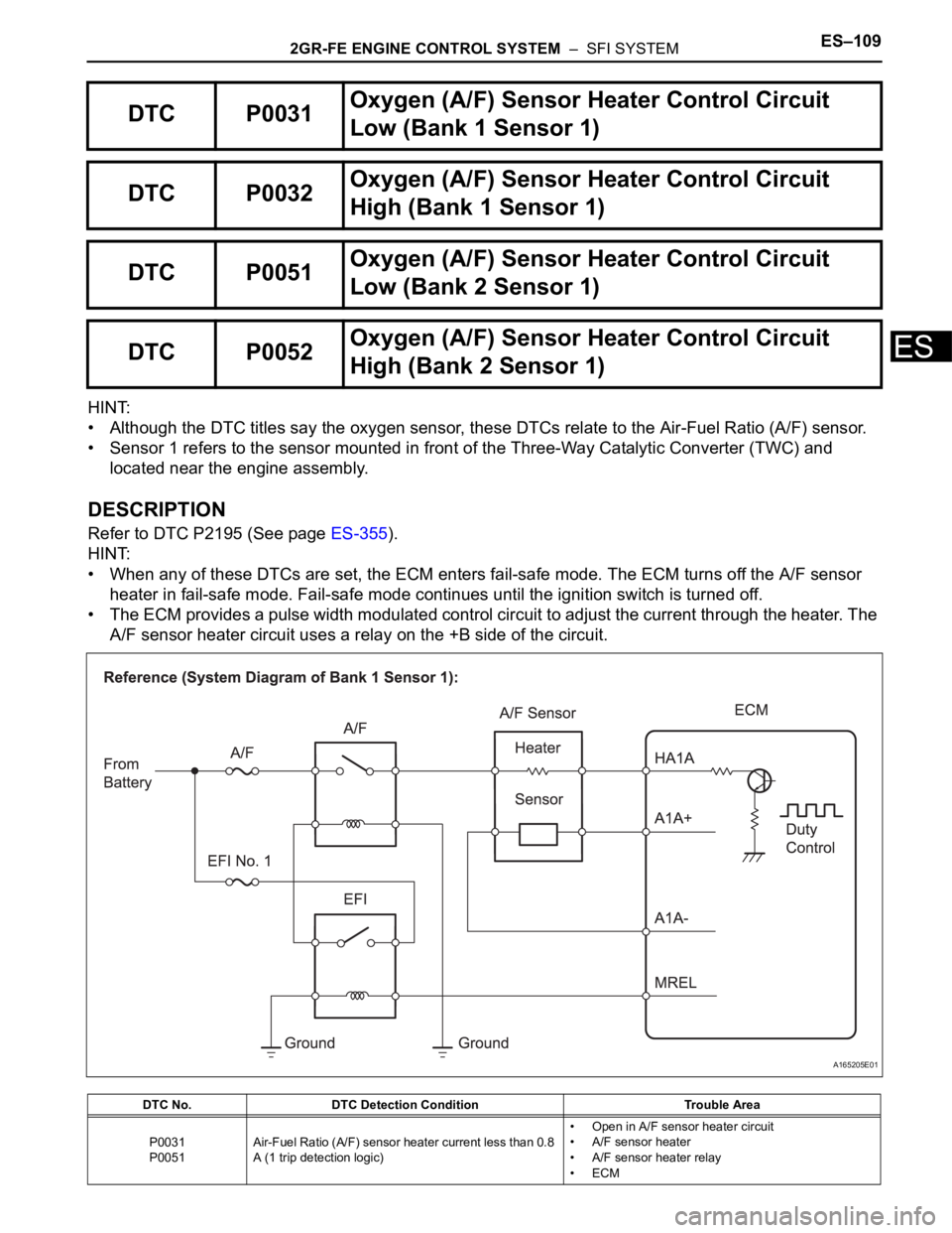
Refer to DTC P2195 (See page ES-355).
HINT:
• When any of these DTCs are set, the ECM enters fail-safe mode. The ECM turns off the A/F sensor
heater in fail-safe mode. Fail-safe mode continues until the ignition switch is turned off.
• The ECM provides a pulse width modulated control circuit to adjust the current through the heater. The
A/F sensor heater circuit uses a relay on the +B side of the circuit.
DTC P0031Oxygen (A/F) Sensor Heater Control Circuit
Low (Bank 1 Sensor 1)
DTC P0032Oxygen (A/F) Sensor Heater Control Circuit
High (Bank 1 Sensor 1)
DTC P0051Oxygen (A/F) Sensor Heater Control Circuit
Low (Bank 2 Sensor 1)
DTC P0052Oxygen (A/F) Sensor Heater Control Circuit
High (Bank 2 Sensor 1)
DTC No. DTC Detection Condition Trouble Area
P0031
P0051Air-Fuel Ratio (A/F) sensor heater current less than 0.8
A (1 trip detection logic)• Open in A/F sensor heater circuit
• A/F sensor heater
• A/F sensor heater relay
•ECM
A165205E01
Page 842 of 3000
EXTERIOR – REAR DOOR WINDOW FRAME MOULDINGET–33
ET
INSTALLATION
1. INSTALL REAR DOOR WINDOW FRAME MOULDING
(a) Remove the tape from the rear door window frame
moulding.
(b) Clean the contact surface of the vehicle body with
white gasoline.
(c) Clean the outer circumference of the rear door
window frame moulding with white gasoline.
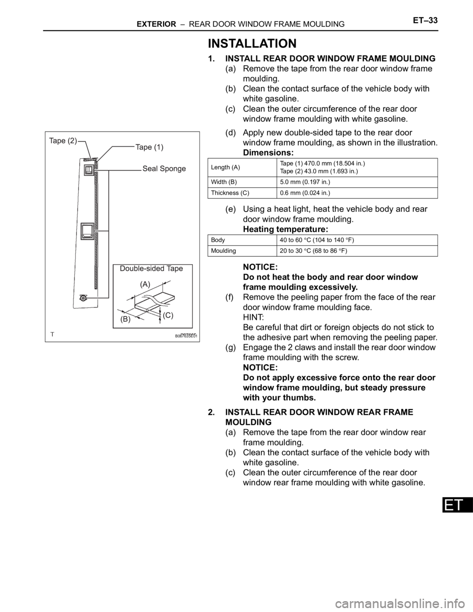
(d) Apply new double-sided tape to the rear door
window frame moulding, as shown in the illustration.
Dimensions:
(e) Using a heat light, heat the vehicle body and rear
door window frame moulding.
Heating temperature:
NOTICE:
Do not heat the body and rear door window
frame moulding excessively.
(f) Remove the peeling paper from the face of the rear
door window frame moulding face.
HINT:
Be careful that dirt or foreign objects do not stick to
the adhesive part when removing the peeling paper.
(g) Engage the 2 claws and install the rear door window
frame moulding with the screw.
NOTICE:
Do not apply excessive force onto the rear door
window frame moulding, but steady pressure
with your thumbs.
2. INSTALL REAR DOOR WINDOW REAR FRAME
MOULDING
(a) Remove the tape from the rear door window rear
frame moulding.
(b) Clean the contact surface of the vehicle body with
white gasoline.
(c) Clean the outer circumference of the rear door
window rear frame moulding with white gasoline.
B067635E01
Length (A)Tape (1) 470.0 mm (18.504 in.)
Tape (2) 43.0 mm (1.693 in.)
Width (B) 5.0 mm (0.197 in.)
Thickness (C) 0.6 mm (0.024 in.)
Body 40 to 60
C (104 to 140 F)
Moulding 20 to 30
C (68 to 86 F)
Page 843 of 3000
ET–34EXTERIOR – REAR DOOR WINDOW FRAME MOULDING
ET
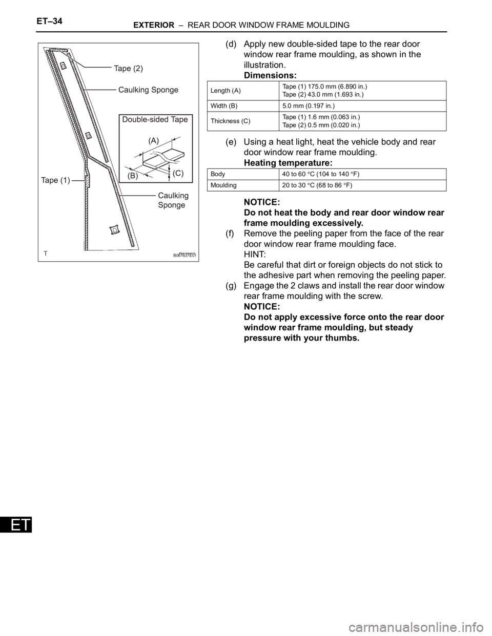
(d) Apply new double-sided tape to the rear door
window rear frame moulding, as shown in the
illustration.
Dimensions:
(e) Using a heat light, heat the vehicle body and rear
door window rear frame moulding.
Heating temperature:
NOTICE:
Do not heat the body and rear door window rear
frame moulding excessively.
(f) Remove the peeling paper from the face of the rear
door window rear frame moulding face.
HINT:
Be careful that dirt or foreign objects do not stick to
the adhesive part when removing the peeling paper.
(g) Engage the 2 claws and install the rear door window
rear frame moulding with the screw.
NOTICE:
Do not apply excessive force onto the rear door
window rear frame moulding, but steady
pressure with your thumbs.
B067637E01
Length (A)Tape (1) 175.0 mm (6.890 in.)
Tape (2) 43.0 mm (1.693 in.)
Width (B) 5.0 mm (0.197 in.)
Thickness (C)Tape (1) 1.6 mm (0.063 in.)
Tape (2) 0.5 mm (0.020 in.)
Body 40 to 60
C (104 to 140 F)
Moulding 20 to 30
C (68 to 86 F)
Page 917 of 3000
EM–1122GR-FE ENGINE MECHANICAL – ENGINE UNIT
EM
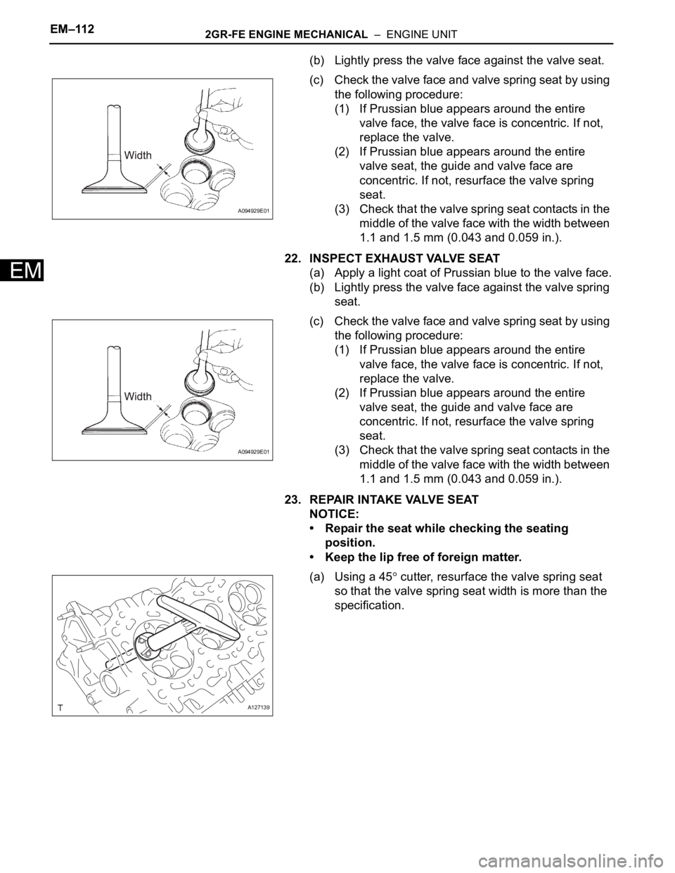
(b) Lightly press the valve face against the valve seat.
(c) Check the valve face and valve spring seat by using
the following procedure:
(1) If Prussian blue appears around the entire
valve face, the valve face is concentric. If not,
replace the valve.
(2) If Prussian blue appears around the entire
valve seat, the guide and valve face are
concentric. If not, resurface the valve spring
seat.
(3) Check that the valve spring seat contacts in the
middle of the valve face with the width between
1.1 and 1.5 mm (0.043 and 0.059 in.).
22. INSPECT EXHAUST VALVE SEAT
(a) Apply a light coat of Prussian blue to the valve face.
(b) Lightly press the valve face against the valve spring
seat.
(c) Check the valve face and valve spring seat by using
the following procedure:
(1) If Prussian blue appears around the entire
valve face, the valve face is concentric. If not,
replace the valve.
(2) If Prussian blue appears around the entire
valve seat, the guide and valve face are
concentric. If not, resurface the valve spring
seat.
(3) Check that the valve spring seat contacts in the
middle of the valve face with the width between
1.1 and 1.5 mm (0.043 and 0.059 in.).
23. REPAIR INTAKE VALVE SEAT
NOTICE:
• Repair the seat while checking the seating
position.
• Keep the lip free of foreign matter.
(a) Using a 45
cutter, resurface the valve spring seat
so that the valve spring seat width is more than the
specification.
A094929E01
A094929E01
A127139
Page 918 of 3000
2GR-FE ENGINE MECHANICAL – ENGINE UNITEM–113
EM
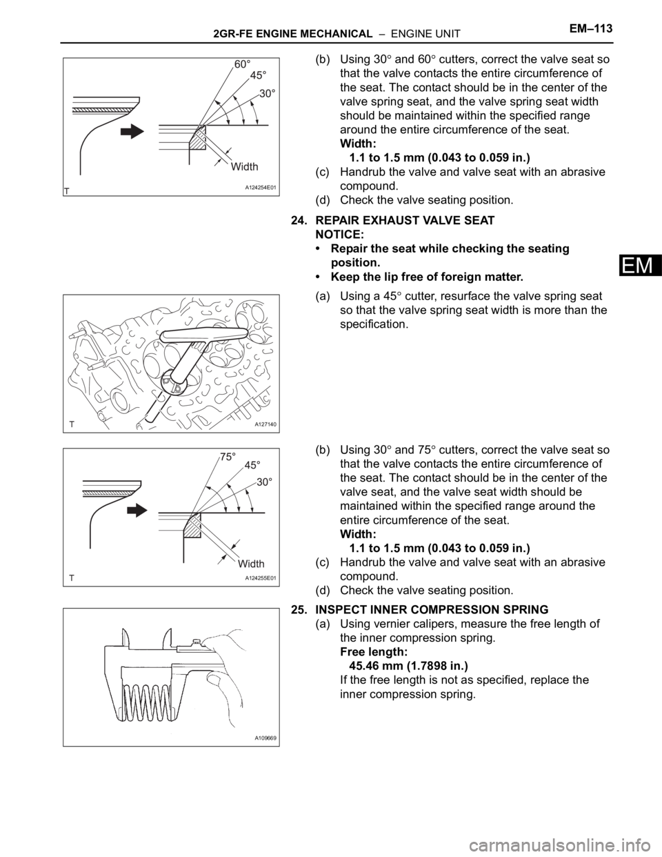
(b) Using 30 and 60 cutters, correct the valve seat so
that the valve contacts the entire circumference of
the seat. The contact should be in the center of the
valve spring seat, and the valve spring seat width
should be maintained within the specified range
around the entire circumference of the seat.
Width:
1.1 to 1.5 mm (0.043 to 0.059 in.)
(c) Handrub the valve and valve seat with an abrasive
compound.
(d) Check the valve seating position.
24. REPAIR EXHAUST VALVE SEAT
NOTICE:
• Repair the seat while checking the seating
position.
• Keep the lip free of foreign matter.
(a) Using a 45
cutter, resurface the valve spring seat
so that the valve spring seat width is more than the
specification.
(b) Using 30
and 75 cutters, correct the valve seat so
that the valve contacts the entire circumference of
the seat. The contact should be in the center of the
valve seat, and the valve seat width should be
maintained within the specified range around the
entire circumference of the seat.
Width:
1.1 to 1.5 mm (0.043 to 0.059 in.)
(c) Handrub the valve and valve seat with an abrasive
compound.
(d) Check the valve seating position.
25. INSPECT INNER COMPRESSION SPRING
(a) Using vernier calipers, measure the free length of
the inner compression spring.
Free length:
45.46 mm (1.7898 in.)
If the free length is not as specified, replace the
inner compression spring.
A124254E01
A127140
A124255E01
A109669
Page 938 of 3000
2GR-FE ENGINE MECHANICAL – ENGINE UNITEM–129
EM
(b) Using a piston ring expander, install the
compression ring as shown in the illustration.
(c) Position the piston rings so that the ring ends are as
shown in the illustration.
NOTICE:
Do not align the ring ends.
6. INSTALL CRANKSHAFT BEARING
(a) Clean the main journal and both surfaces of the
bearing.
NOTICE:
Main bearings come in widths between 18.0 mm
(0.709 in.) and 21.0 mm (0.827 in.). Install the
21.0 mm (0.827 in.) bearings in the No. 1 and No.
4 cylinder block journal positions with the main
bearing cap. Install the 18.0 mm (0.709 in.)
bearings in the No. 2 and No. 3 positions.
A131880E03
A131881E01
A124282E02
Page 1059 of 3000
EM–1122GR-FE ENGINE MECHANICAL – ENGINE UNIT
EM
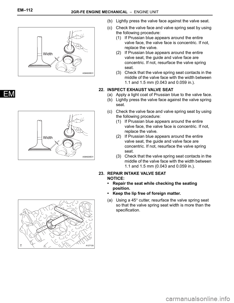
(b) Lightly press the valve face against the valve seat.
(c) Check the valve face and valve spring seat by using
the following procedure:
(1) If Prussian blue appears around the entire
valve face, the valve face is concentric. If not,
replace the valve.
(2) If Prussian blue appears around the entire
valve seat, the guide and valve face are
concentric. If not, resurface the valve spring
seat.
(3) Check that the valve spring seat contacts in the
middle of the valve face with the width between
1.1 and 1.5 mm (0.043 and 0.059 in.).
22. INSPECT EXHAUST VALVE SEAT
(a) Apply a light coat of Prussian blue to the valve face.
(b) Lightly press the valve face against the valve spring
seat.
(c) Check the valve face and valve spring seat by using
the following procedure:
(1) If Prussian blue appears around the entire
valve face, the valve face is concentric. If not,
replace the valve.
(2) If Prussian blue appears around the entire
valve seat, the guide and valve face are
concentric. If not, resurface the valve spring
seat.
(3) Check that the valve spring seat contacts in the
middle of the valve face with the width between
1.1 and 1.5 mm (0.043 and 0.059 in.).
23. REPAIR INTAKE VALVE SEAT
NOTICE:
• Repair the seat while checking the seating
position.
• Keep the lip free of foreign matter.
(a) Using a 45
cutter, resurface the valve spring seat
so that the valve spring seat width is more than the
specification.
A094929E01
A094929E01
A127139