2007 TOYOTA SIENNA Transaxle
[x] Cancel search: TransaxlePage 16 of 3000

SS–30SERVICE SPECIFICATIONS – U151E AUTOMATIC TRANSAXLE
SS
TORQUE SPECIFICATIONS
Part Tightened N*m kgf*cm ft*lbf
Park/neutral position switch Nut 6.9 70 61 in.*lbf
Bolt 5.4 55 48 in.*lbf
Control shaft lever x Control shaft 13 130 9
Shift control cable x Control shaft lever 13 130 9
Transaxle housing x Engine block A bolt 64 653 47
B bolt 46 470 34
C bolt 43 439 32
Torque converter clutch x Drive plate 41 413 35
Flywheel housing under cover x Automatic transaxle 7.8 80 69 in.*lbf
Engine mounting bracket FR x Transaxle 64 653 47
Oil filler tube x Transaxle5.5 56 49 in.*lbf
Control cable bracket No. 1 x Transaxle 12 122 9
Control cable bracket No. 2 x Transaxle 12 122 9
Oil cooler tube clamp x Control cable bracket 5.5 56 49 in.*lbf
Oil cooler inlet tube x Transaxle27 275 20
Oil cooler outlet tube x Transaxle 27 275 20
Starter x Transaxle37 377 27
Starter wire x Starter9.8 100 87 in.*lbf
Wire harness x Transaxle13 133 10
Wire harness clamp x Transaxle8.4 86 74 in.*lbf
Speed sensor (NC) x Transaxle11 11 5 8
Speed sensor (NT) x Transaxle11 11 2 8
Air cleaner x Air cleaner hose5.0 51 44 in.*lbf
Drain plug x Oil pan49 500 36
Transmission wire x Transaxle5.4 55 48 in.*lbf
ATF temperature sensor x Valve body 6.6 67 58 in.*lbf
Oil pan x Transaxle7.8 80 69 in.*lbf
Solenoid valve x Valve body A B bolt 11 110 8
C D bolt 6.6 67 58 in.*lbf
Valve body x Transaxle11 11 0 8
Oil strainer x Valve body11 11 0 8
Floor shift assembly x Body21 214 15
Control cable x Body12 122 9
Engine mount bracket RR x Transfer stiffener plate RH 34 350 25
Oil cooler assembly x Body Nut
7.0 71 62 in.*lbf
bolt
Differential gear lube apply tube x Transaxle housing 9.8 100 87 in.*lbf
Front planetary gear lock nut
210 to 3502,141 to
3,569155 to 258
Brake apply tube clamp x Transaxle case 5.4 55 48 in.*lbf
Transaxle case No. 1 plug x Transaxle rear cover 7.4 75 65 in.*lbf
Transaxle rear cover x Transaxle case Bolt A 19 190 14
Other bolt 25 250 18
Pawl shaft clamp x Transaxle case 9.8 100 87 in.*lbf
Oil pump assembly x Transaxle case 22 226 16
Page 17 of 3000

SERVICE SPECIFICATIONS – U151E AUTOMATIC TRANSAXLESS–31
SS
Transaxle housing x Transaxle case Bolt A 22 225 16
Bolt B 29 300 22
Bolt C 29 295 21
Bolt D 22 226 16
Automatic transmission case plug x Transaxle housing 7.4 75 65 in.*lbf
Automatic transmission case plug x Transaxle case 7.4 75 65 in.*lbf
Parking lock pawl bracket x Transaxle case 20 205 15
Manual detent spring x Transaxle case Bolt A 20 205 15
Bolt B 12 120 9
Transmission wire x Transaxle housing 5.4 55 48 in.*lbf
Transmission valve body x Transaxle case 11 110 8
ATF temperature sensor clamp x Transmission valve body 6.6 67 58 in.*lbf
Valve body oil strainer assembly x Transmission valve body 11 1108
Automatic transaxle oil pan sub-assembly x Transaxle case 7.8 80 69 in.*lbf
Drain plug x Automatic transaxle oil pan sub-assembly 49 500 36
Speed sensor x Transaxle case11 11 5 8
Oil cooler tube union x Transaxle case Union 27 276 20
Elbow 27 276 20
Park/neutral start switch x nut6.9 70 61 in.*lbf
Park/neutral start switch x Bolt5.4 55 48 in.*lbf
Park/neutral start switch x Control shaft lever 13 130 9
Speedometer driven hole cover sub-assembly x Transaxle case 6.9 7061
Oil pump body x Stator shaft assembly 9.8 100 87 in.*lbf
Line pressure control solenoid assembly x Transmission valve body assembly 6.6 67 58 in.*lbf
Shift solenoid valve SL1 x Transmission valve body assembly 6.6 67 58 in.*lbf
Shift solenoid valve SL2 x Transmission valve body assembly 10.811 0 8
Shift solenoid valve SL3 x Transmission valve body assembly 6.6 67 58 in.*lbf
Shift solenoid valve S4 x Transmission valve body assembly 10.8 110 8
Shift solenoid valve DSL x Transmission valve body assembly 10.811 0 8
Front differential case x Front differential ring gear 95.1 970 70Part Tightened N*m kgf*cm ft*lbf
Page 25 of 3000

EM–262GR-FE ENGINE MECHANICAL – ENGINE ASSEMBLY
EM
REMOVAL
1. DISCHARGE FUEL SYSTEM PRESSURE (See page
FU-13)
2. DISCHARGE REFRIGERANT FROM
REFRIGERATION SYSTEM (See page AC-172)
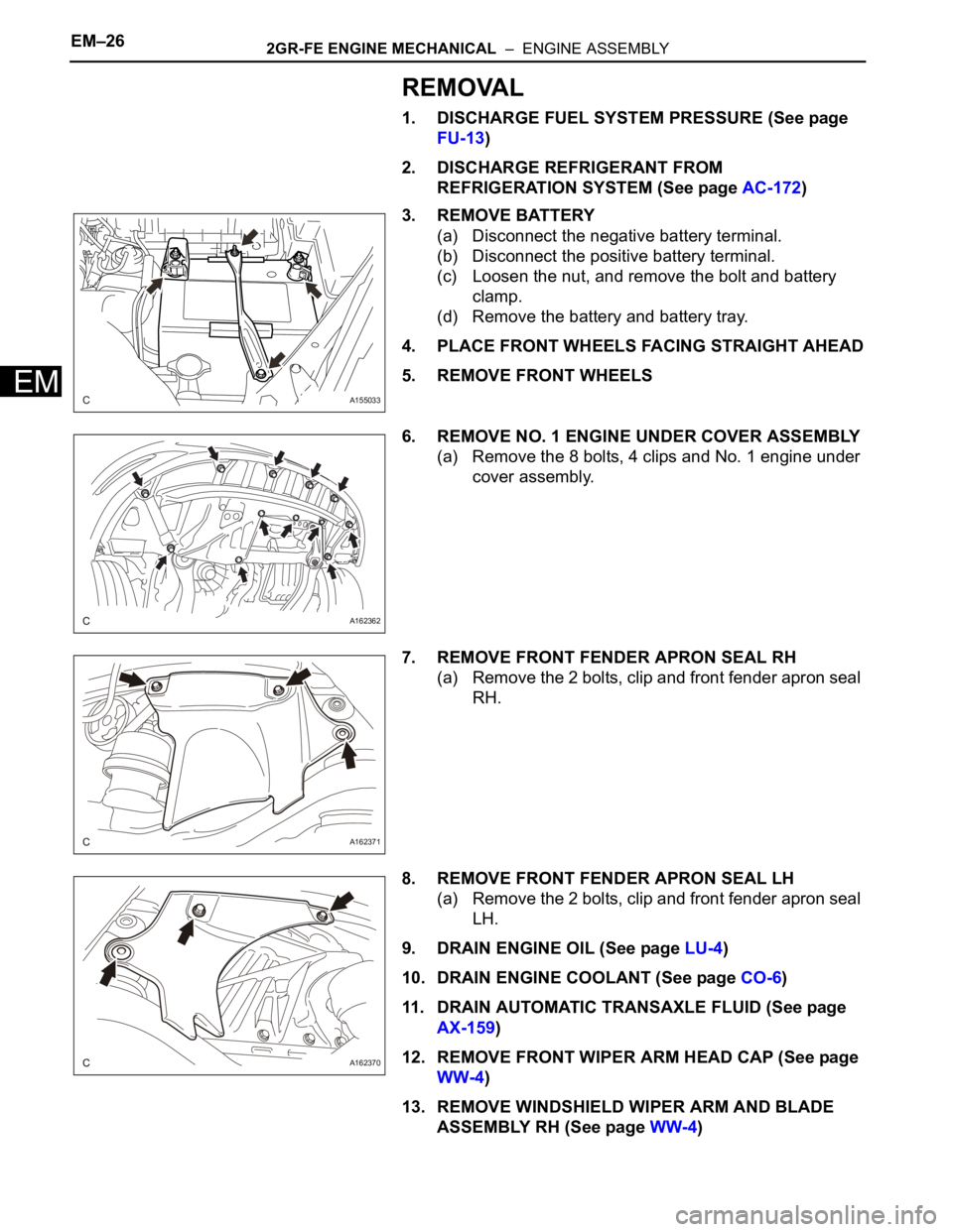
3. REMOVE BATTERY
(a) Disconnect the negative battery terminal.
(b) Disconnect the positive battery terminal.
(c) Loosen the nut, and remove the bolt and battery
clamp.
(d) Remove the battery and battery tray.
4. PLACE FRONT WHEELS FACING STRAIGHT AHEAD
5. REMOVE FRONT WHEELS
6. REMOVE NO. 1 ENGINE UNDER COVER ASSEMBLY
(a) Remove the 8 bolts, 4 clips and No. 1 engine under
cover assembly.
7. REMOVE FRONT FENDER APRON SEAL RH
(a) Remove the 2 bolts, clip and front fender apron seal
RH.
8. REMOVE FRONT FENDER APRON SEAL LH
(a) Remove the 2 bolts, clip and front fender apron seal
LH.
9. DRAIN ENGINE OIL (See page LU-4)
10. DRAIN ENGINE COOLANT (See page CO-6)
11. DRAIN AUTOMATIC TRANSAXLE FLUID (See page
AX-159)
12. REMOVE FRONT WIPER ARM HEAD CAP (See page
WW-4)
13. REMOVE WINDSHIELD WIPER ARM AND BLADE
ASSEMBLY RH (See page WW-4)
A155033
A162362
A162371
A162370
Page 33 of 3000

EM–342GR-FE ENGINE MECHANICAL – ENGINE ASSEMBLY
EM
45. REMOVE PROPELLER WITH CENTER BEARING
SHAFT ASSEMBLY (See page PR-3)
46. DISCONNECT FRONT STABILIZER LINK ASSEMBLY
LH (See page DS-5)
47. DISCONNECT FRONT STABILIZER LINK ASSEMBLY
RH
HINT:
Use the same procedures described for the LH side.
48. REMOVE FRONT AXLE HUB NUT LH (See page DS-
5)
49. REMOVE FRONT AXLE HUB NUT RH
HINT:
Use the same procedures described for the LH side.
50. DISCONNECT FRONT SPEED SENSOR LH (See page
DS-5)
51. DISCONNECT FRONT SPEED SENSOR RH
HINT:
Use the same procedures described for the LH side.
52. DISCONNECT TIE ROD ASSEMBLY LH (See page
DS-6)
53. DISCONNECT TIE ROD ASSEMBLY RH
HINT:
Use the same procedures described for the LH side.
54. SEPARATE FRONT SUSPENSION LOWER NO. 1
ARM LH (See page DS-6)
55. SEPARATE FRONT SUSPENSION LOWER NO. 1
ARM RH
HINT:
Use the same procedures described for the LH side.
56. SEPARATE FRONT AXLE ASSEMBLY LH (See page
DS-6)
57. SEPARATE FRONT AXLE ASSEMBLY RH
HINT:
Use the same procedures described for the LH side.
58. DISCONNECT STEERING INTERMEDIATE SHAFT
SUB-ASSEMBLY
59. DISCONNECT DISCHARGE HOSE SUB-ASSEMBLY
(See page AC-227)
60. DISCONNECT SUCTION HOSE SUB-ASSEMBLY (See
page AC-227)
61. REMOVE ENGINE ASSEMBLY WITH TRANSAXLE
(a) Set the engine lifter.
Page 36 of 3000

2GR-FE ENGINE MECHANICAL – ENGINE ASSEMBLYEM–37
EM
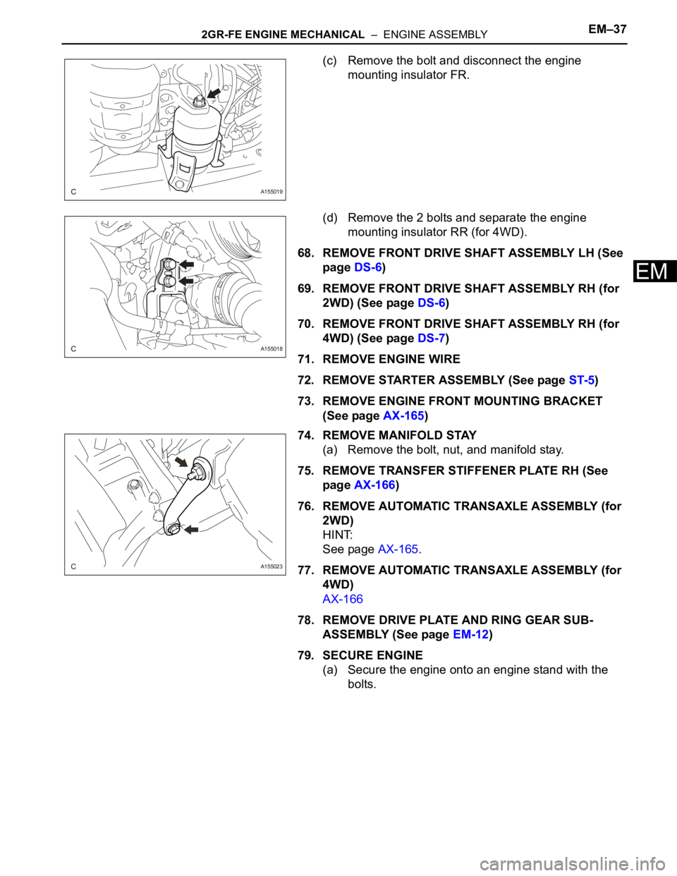
(c) Remove the bolt and disconnect the engine
mounting insulator FR.
(d) Remove the 2 bolts and separate the engine
mounting insulator RR (for 4WD).
68. REMOVE FRONT DRIVE SHAFT ASSEMBLY LH (See
page DS-6)
69. REMOVE FRONT DRIVE SHAFT ASSEMBLY RH (for
2WD) (See page DS-6)
70. REMOVE FRONT DRIVE SHAFT ASSEMBLY RH (for
4WD) (See page DS-7)
71. REMOVE ENGINE WIRE
72. REMOVE STARTER ASSEMBLY (See page ST-5)
73. REMOVE ENGINE FRONT MOUNTING BRACKET
(See page AX-165)
74. REMOVE MANIFOLD STAY
(a) Remove the bolt, nut, and manifold stay.
75. REMOVE TRANSFER STIFFENER PLATE RH (See
page AX-166)
76. REMOVE AUTOMATIC TRANSAXLE ASSEMBLY (for
2WD)
HINT:
See page AX-165.
77. REMOVE AUTOMATIC TRANSAXLE ASSEMBLY (for
4WD)
AX-166
78. REMOVE DRIVE PLATE AND RING GEAR SUB-
ASSEMBLY (See page EM-12)
79. SECURE ENGINE
(a) Secure the engine onto an engine stand with the
bolts.
A155019
A155018
A155023
Page 50 of 3000

IN–38INTRODUCTION – HOW TO TROUBLESHOOT ECU CONTROLLED SYSTEMS
IN
HINT:
• In troubleshooting, confirm that the problem symptoms
have been accurately identified. Preconceptions should be
discarded in order to make an accurate judgment. To
clearly understand what the problem symptoms are, it is
extremely important to ask the customer about the
problem and the conditions at the time the malfunction
occurred.
• Gather as much information as possible for reference.
Past problems that seem unrelated may also help in some
cases.
• The following 5 items are important points in the problem
analysis:
3. SYMPTOM CONFIRMATION AND DIAGNOSTIC
TROUBLE CODE
HINT:
The diagnostic system in the SIENNA has various
functions.
• The first function is the Diagnostic Trouble Code
(DTC) check. A DTC is a code stored in the ECU
memory whenever a malfunction in the signal circuits
to the ECU occurs. In a DTC check, a previous
malfunction's DTC can be checked by a technician
during troubleshooting.
• Another function is the Input Signal Check, which
checks if the signals from various switches are sent to
the ECU correctly.
By using these functions, the problem areas can be
narrowed down and troubleshooting is more effective.
Diagnostic functions are incorporated in the following
system in the SIENNA.
What Vehicle model, system name
When Date, time, occurrence frequency
Where Road conditions
Under what conditions? Running conditions, driving conditions, weather conditions
How did it happen? Problem symptoms
SystemSYMPTOM CONFIRMATION AND DIAGNOSTIC TROUBLE CODE
DTC Check
(Normal Mode)DTC Check
(Check Mode)Sensor Check/
Test Mode
(Input Signal
Check)Data List Active Test
2GR-FE SFI System
X
U151E Automatic Transaxle SystemX
U151F Automatic Transaxle SystemX
Tire pressure warning systemXX
Anti-lock Brake System
X
Vehicle Stability Control SystemX
Air Conditioning System (for Manual Air
Conditioning System)XXXXX
Air Conditioning System (for Automatic Air
Conditioning System)
XX
Airbag SystemXX
Occupant Classification System
XXX
Page 68 of 3000

IN–38INTRODUCTION – HOW TO TROUBLESHOOT ECU CONTROLLED SYSTEMS
IN
HINT:
• In troubleshooting, confirm that the problem symptoms
have been accurately identified. Preconceptions should be
discarded in order to make an accurate judgment. To
clearly understand what the problem symptoms are, it is
extremely important to ask the customer about the
problem and the conditions at the time the malfunction
occurred.
• Gather as much information as possible for reference.
Past problems that seem unrelated may also help in some
cases.
• The following 5 items are important points in the problem
analysis:
3. SYMPTOM CONFIRMATION AND DIAGNOSTIC
TROUBLE CODE
HINT:
The diagnostic system in the SIENNA has various
functions.
• The first function is the Diagnostic Trouble Code
(DTC) check. A DTC is a code stored in the ECU
memory whenever a malfunction in the signal circuits
to the ECU occurs. In a DTC check, a previous
malfunction's DTC can be checked by a technician
during troubleshooting.
• Another function is the Input Signal Check, which
checks if the signals from various switches are sent to
the ECU correctly.
By using these functions, the problem areas can be
narrowed down and troubleshooting is more effective.
Diagnostic functions are incorporated in the following
system in the SIENNA.
What Vehicle model, system name
When Date, time, occurrence frequency
Where Road conditions
Under what conditions? Running conditions, driving conditions, weather conditions
How did it happen? Problem symptoms
SystemSYMPTOM CONFIRMATION AND DIAGNOSTIC TROUBLE CODE
DTC Check
(Normal Mode)DTC Check
(Check Mode)Sensor Check/
Test Mode
(Input Signal
Check)Data List Active Test
2GR-FE SFI System
X
U151E Automatic Transaxle SystemX
U151F Automatic Transaxle SystemX
Tire pressure warning systemXX
Anti-lock Brake System
X
Vehicle Stability Control SystemX
Air Conditioning System (for Manual Air
Conditioning System)XXXXX
Air Conditioning System (for Automatic Air
Conditioning System)
XX
Airbag SystemXX
Occupant Classification System
XXX
Page 78 of 3000

2GR-FE LUBRICATION – OIL PUMPLU–11
LU
REMOVAL
1. REMOVE ENGINE ASSEMBLY WITH TRANSAXLE
HINT:
See page EM-26
2. REMOVE OIL LEVEL GAUGE GUIDE SUB-
ASSEMBLY (See page EM-39)
3. REMOVE NO. 1 OIL PIPE (See page EM-77)
4. REMOVE OIL PIPE (See page EM-77)
5. REMOVE CRANKSHAFT PULLEY (See page EM-79)
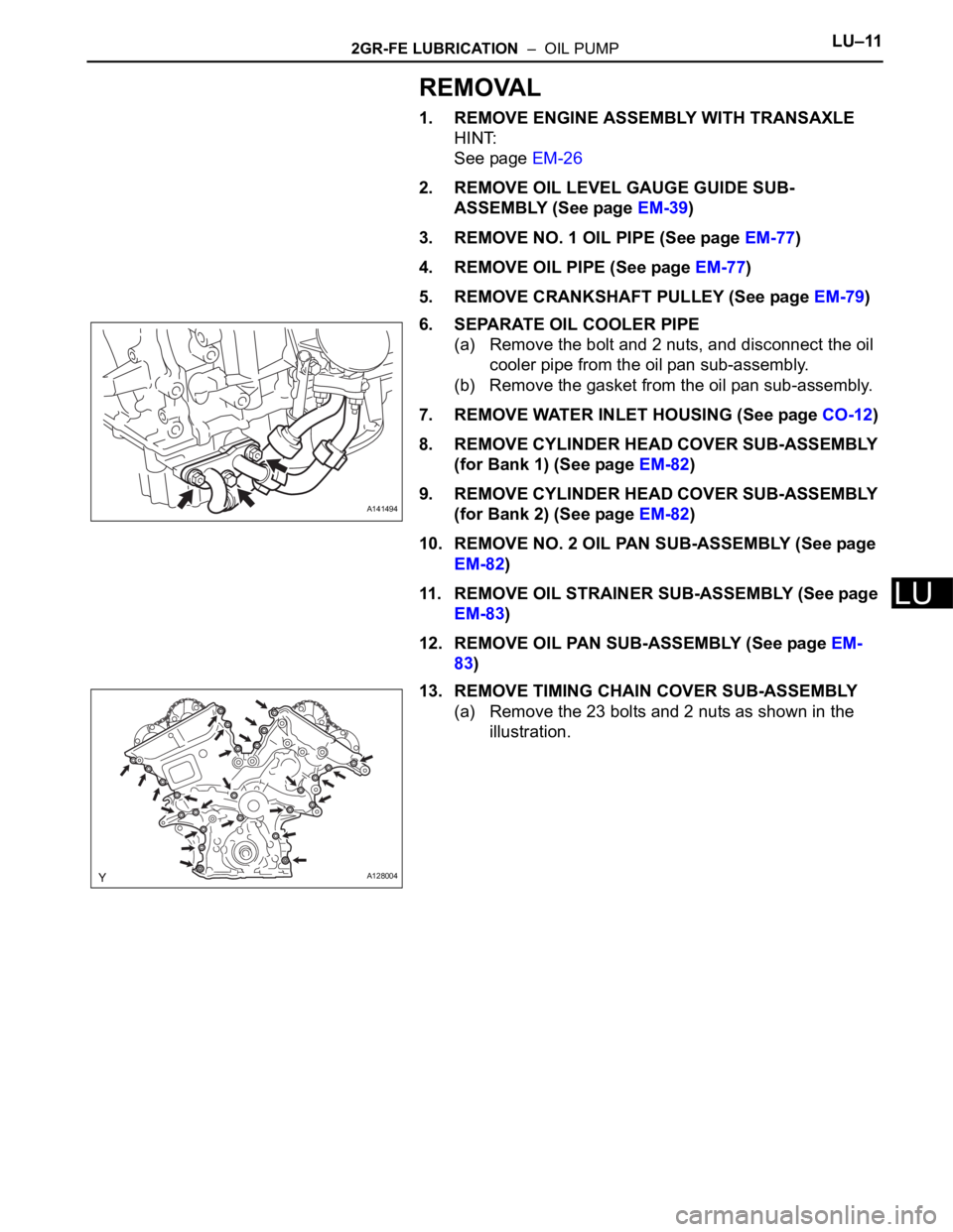
6. SEPARATE OIL COOLER PIPE
(a) Remove the bolt and 2 nuts, and disconnect the oil
cooler pipe from the oil pan sub-assembly.
(b) Remove the gasket from the oil pan sub-assembly.
7. REMOVE WATER INLET HOUSING (See page CO-12)
8. REMOVE CYLINDER HEAD COVER SUB-ASSEMBLY
(for Bank 1) (See page EM-82)
9. REMOVE CYLINDER HEAD COVER SUB-ASSEMBLY
(for Bank 2) (See page EM-82)
10. REMOVE NO. 2 OIL PAN SUB-ASSEMBLY (See page
EM-82)
11. REMOVE OIL STRAINER SUB-ASSEMBLY (See page
EM-83)
12. REMOVE OIL PAN SUB-ASSEMBLY (See page EM-
83)
13. REMOVE TIMING CHAIN COVER SUB-ASSEMBLY
(a) Remove the 23 bolts and 2 nuts as shown in the
illustration.
A141494
A128004