Page 104 of 3000
U151F AUTOMATIC TRANSAXLE – AUTOMATIC TRANSAXLE ASSEMBLYAX–169
AX
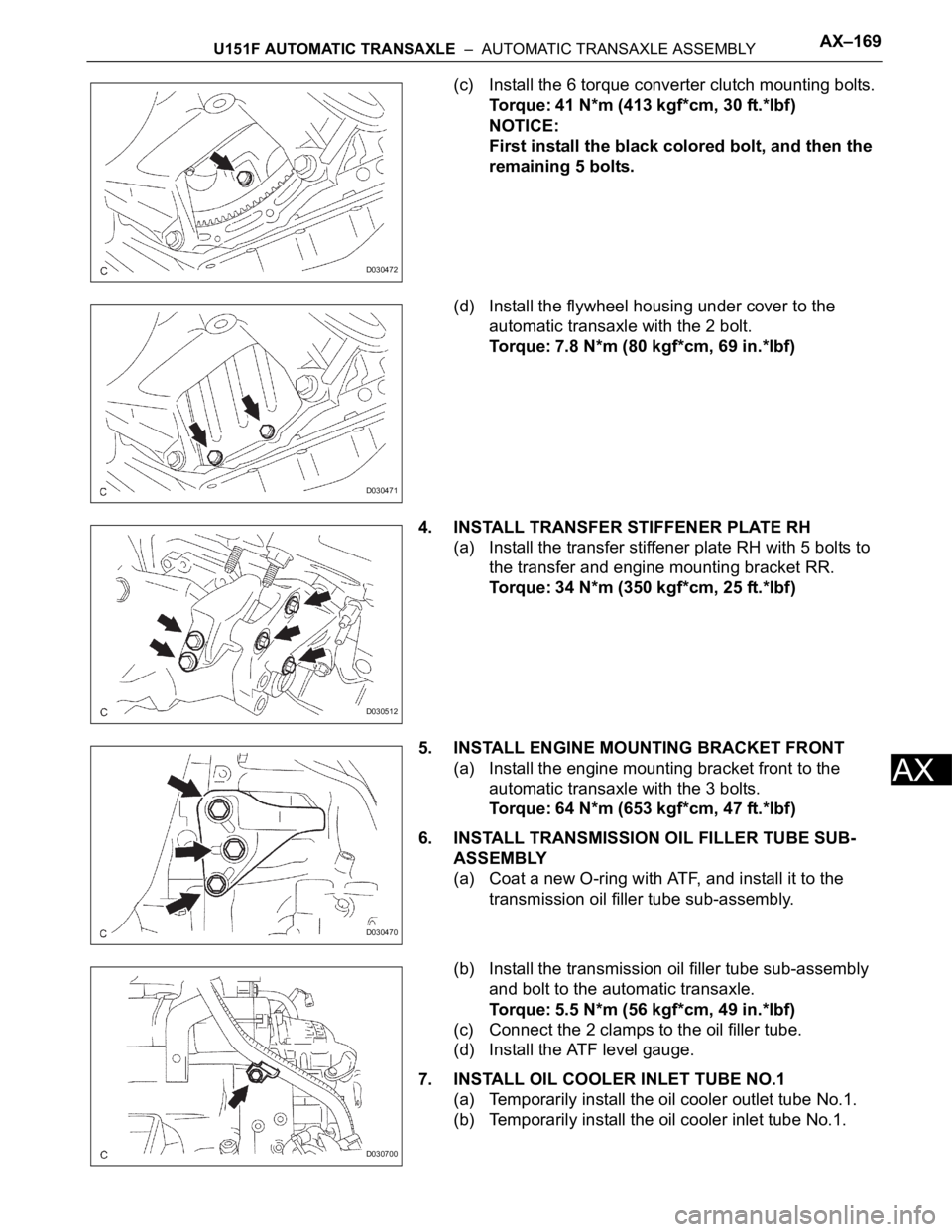
(c) Install the 6 torque converter clutch mounting bolts.
Torque: 41 N*m (413 kgf*cm, 30 ft.*lbf)
NOTICE:
First install the black colored bolt, and then the
remaining 5 bolts.
(d) Install the flywheel housing under cover to the
automatic transaxle with the 2 bolt.
Torque: 7.8 N*m (80 kgf*cm, 69 in.*lbf)
4. INSTALL TRANSFER STIFFENER PLATE RH
(a) Install the transfer stiffener plate RH with 5 bolts to
the transfer and engine mounting bracket RR.
Torque: 34 N*m (350 kgf*cm, 25 ft.*lbf)
5. INSTALL ENGINE MOUNTING BRACKET FRONT
(a) Install the engine mounting bracket front to the
automatic transaxle with the 3 bolts.
Torque: 64 N*m (653 kgf*cm, 47 ft.*lbf)
6. INSTALL TRANSMISSION OIL FILLER TUBE SUB-
ASSEMBLY
(a) Coat a new O-ring with ATF, and install it to the
transmission oil filler tube sub-assembly.
(b) Install the transmission oil filler tube sub-assembly
and bolt to the automatic transaxle.
Torque: 5.5 N*m (56 kgf*cm, 49 in.*lbf)
(c) Connect the 2 clamps to the oil filler tube.
(d) Install the ATF level gauge.
7. INSTALL OIL COOLER INLET TUBE NO.1
(a) Temporarily install the oil cooler outlet tube No.1.
(b) Temporarily install the oil cooler inlet tube No.1.
D030472
D030471
D030512
D030470
D030700
Page 105 of 3000
AX–170U151F AUTOMATIC TRANSAXLE – AUTOMATIC TRANSAXLE ASSEMBLY
AX
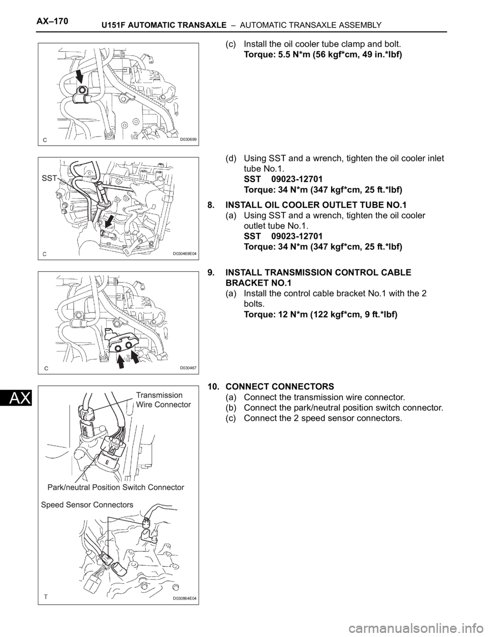
(c) Install the oil cooler tube clamp and bolt.
Torque: 5.5 N*m (56 kgf*cm, 49 in.*lbf)
(d) Using SST and a wrench, tighten the oil cooler inlet
tube No.1.
SST 09023-12701
Torque: 34 N*m (347 kgf*cm, 25 ft.*lbf)
8. INSTALL OIL COOLER OUTLET TUBE NO.1
(a) Using SST and a wrench, tighten the oil cooler
outlet tube No.1.
SST 09023-12701
Torque: 34 N*m (347 kgf*cm, 25 ft.*lbf)
9. INSTALL TRANSMISSION CONTROL CABLE
BRACKET NO.1
(a) Install the control cable bracket No.1 with the 2
bolts.
Torque: 12 N*m (122 kgf*cm, 9 ft.*lbf)
10. CONNECT CONNECTORS
(a) Connect the transmission wire connector.
(b) Connect the park/neutral position switch connector.
(c) Connect the 2 speed sensor connectors.
D030699
D030469E04
D030467
D030864E04
Page 106 of 3000
U151F AUTOMATIC TRANSAXLE – AUTOMATIC TRANSAXLE ASSEMBLYAX–171
AX
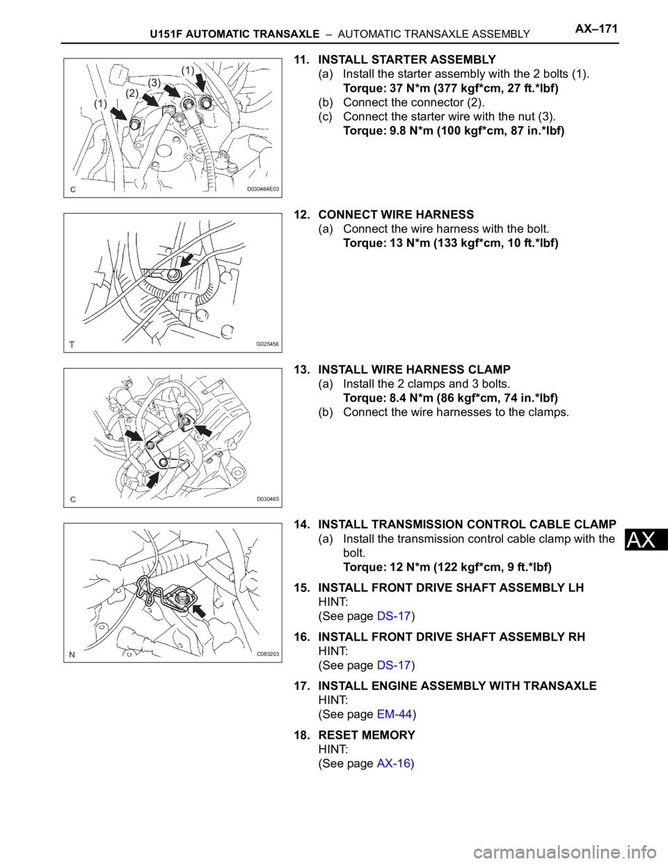
11. INSTALL STARTER ASSEMBLY
(a) Install the starter assembly with the 2 bolts (1).
Torque: 37 N*m (377 kgf*cm, 27 ft.*lbf)
(b) Connect the connector (2).
(c) Connect the starter wire with the nut (3).
Torque: 9.8 N*m (100 kgf*cm, 87 in.*lbf)
12. CONNECT WIRE HARNESS
(a) Connect the wire harness with the bolt.
Torque: 13 N*m (133 kgf*cm, 10 ft.*lbf)
13. INSTALL WIRE HARNESS CLAMP
(a) Install the 2 clamps and 3 bolts.
Torque: 8.4 N*m (86 kgf*cm, 74 in.*lbf)
(b) Connect the wire harnesses to the clamps.
14. INSTALL TRANSMISSION CONTROL CABLE CLAMP
(a) Install the transmission control cable clamp with the
bolt.
Torque: 12 N*m (122 kgf*cm, 9 ft.*lbf)
15. INSTALL FRONT DRIVE SHAFT ASSEMBLY LH
HINT:
(See page DS-17)
16. INSTALL FRONT DRIVE SHAFT ASSEMBLY RH
HINT:
(See page DS-17)
17. INSTALL ENGINE ASSEMBLY WITH TRANSAXLE
HINT:
(See page EM-44)
18. RESET MEMORY
HINT:
(See page AX-16)
D030464E03
G025456
D030465
C083203
Page 107 of 3000
TRANSFER – TRANSFER ASSEMBLYTF–9
TF
INSTALLATION
1. INSTALL TRANSFER ASSEMBLY
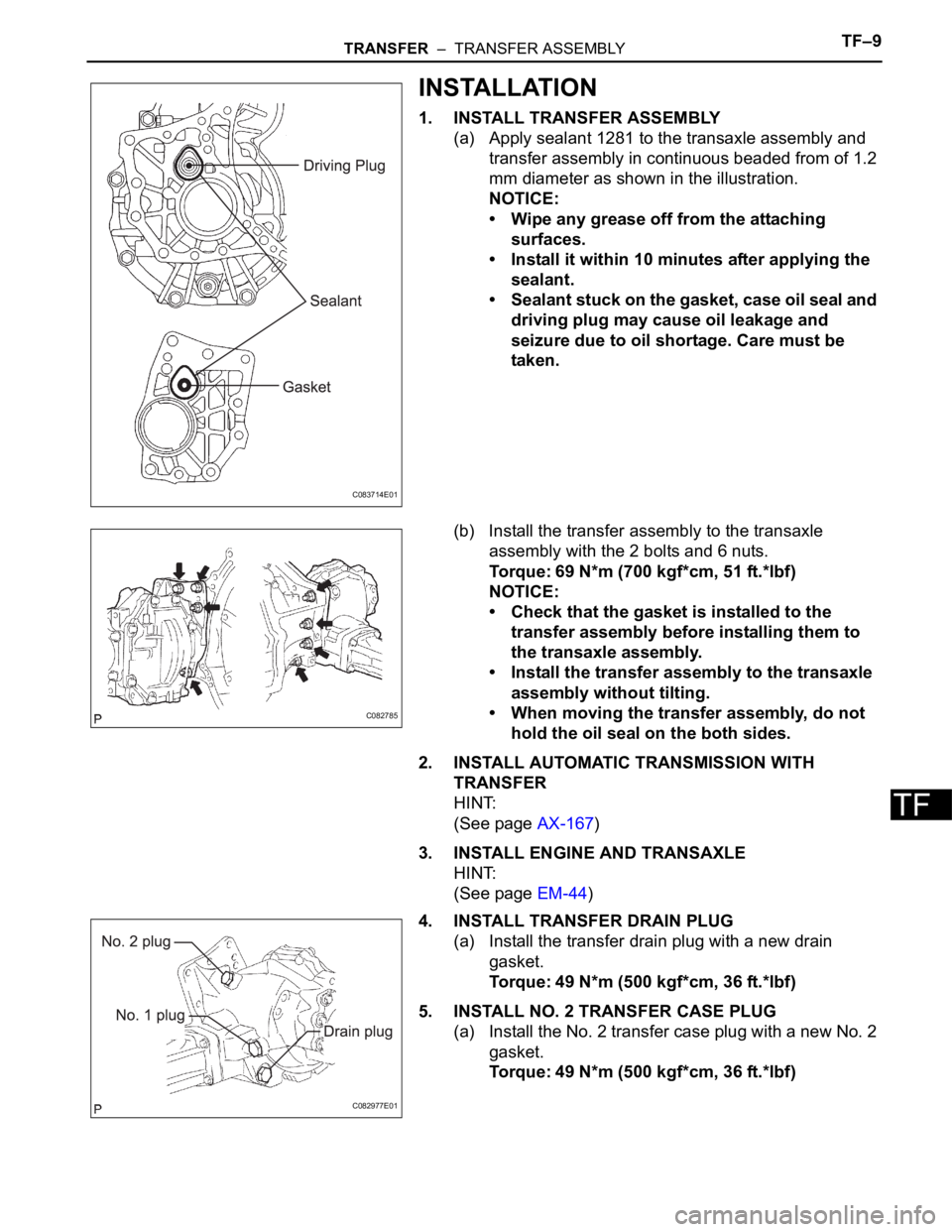
(a) Apply sealant 1281 to the transaxle assembly and
transfer assembly in continuous beaded from of 1.2
mm diameter as shown in the illustration.
NOTICE:
• Wipe any grease off from the attaching
surfaces.
• Install it within 10 minutes after applying the
sealant.
• Sealant stuck on the gasket, case oil seal and
driving plug may cause oil leakage and
seizure due to oil shortage. Care must be
taken.
(b) Install the transfer assembly to the transaxle
assembly with the 2 bolts and 6 nuts.
Torque: 69 N*m (700 kgf*cm, 51 ft.*lbf)
NOTICE:
• Check that the gasket is installed to the
transfer assembly before installing them to
the transaxle assembly.
• Install the transfer assembly to the transaxle
assembly without tilting.
• When moving the transfer assembly, do not
hold the oil seal on the both sides.
2. INSTALL AUTOMATIC TRANSMISSION WITH
TRANSFER
HINT:
(See page AX-167)
3. INSTALL ENGINE AND TRANSAXLE
HINT:
(See page EM-44)
4. INSTALL TRANSFER DRAIN PLUG
(a) Install the transfer drain plug with a new drain
gasket.
Torque: 49 N*m (500 kgf*cm, 36 ft.*lbf)
5. INSTALL NO. 2 TRANSFER CASE PLUG
(a) Install the No. 2 transfer case plug with a new No. 2
gasket.
Torque: 49 N*m (500 kgf*cm, 36 ft.*lbf)
C083714E01
C082785
C082977E01
Page 110 of 3000
DRIVE SHAFT – FRONT DRIVE SHAFTDS–5
DS
REMOVAL
1. DRAIN AUTOMATIC TRANSAXLE FLUID
(a) Remove the drain plug, gasket and drain ATF.
(b) Install a new gasket and the drain plug.
Torque: 49 N*m (500 kgf*cm, 36 ft.*lbf)
2. DRAIN TRANSFER OIL (for 4WD)
HINT:
(See page TF-8)
3. REMOVE FRONT WHEEL
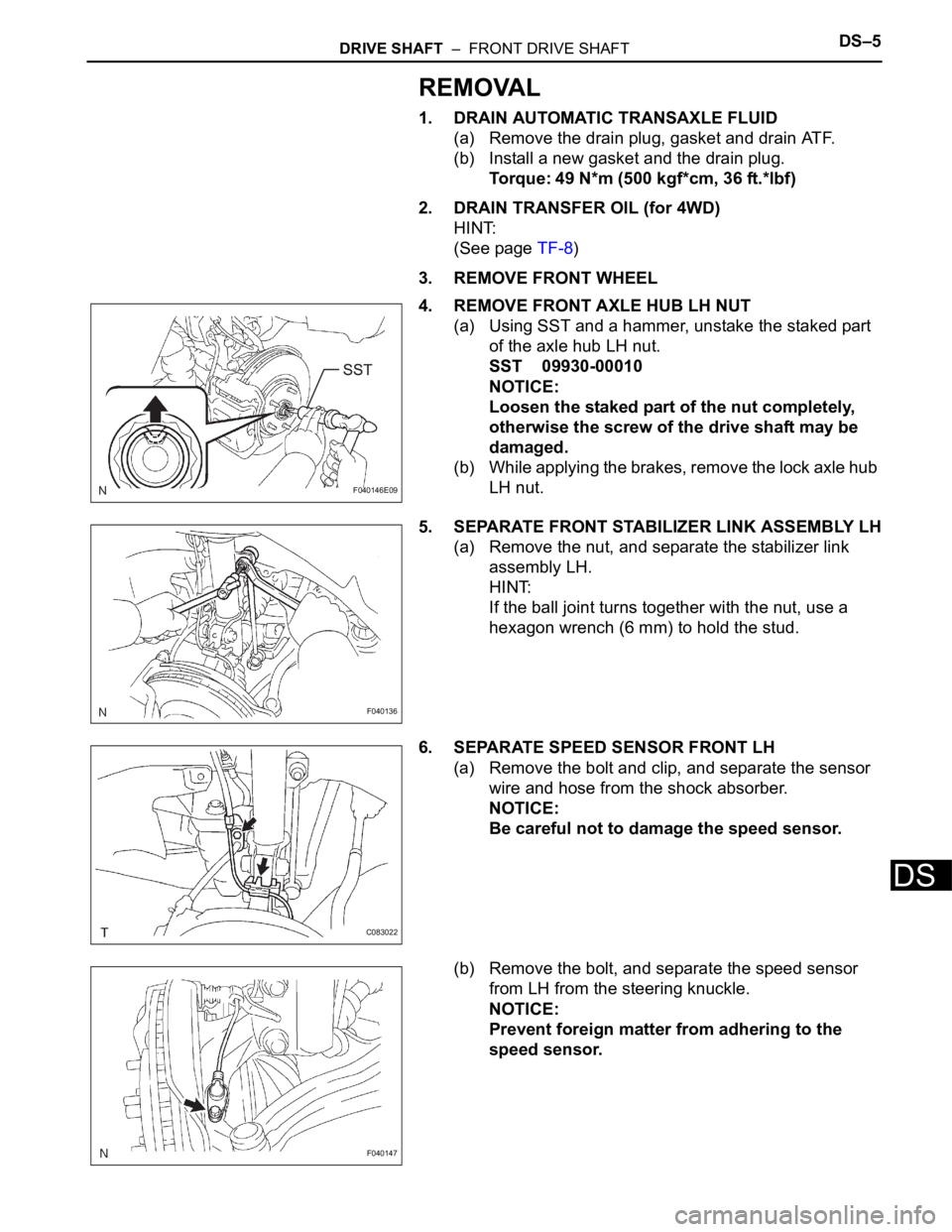
4. REMOVE FRONT AXLE HUB LH NUT
(a) Using SST and a hammer, unstake the staked part
of the axle hub LH nut.
SST 09930-00010
NOTICE:
Loosen the staked part of the nut completely,
otherwise the screw of the drive shaft may be
damaged.
(b) While applying the brakes, remove the lock axle hub
LH nut.
5. SEPARATE FRONT STABILIZER LINK ASSEMBLY LH
(a) Remove the nut, and separate the stabilizer link
assembly LH.
HINT:
If the ball joint turns together with the nut, use a
hexagon wrench (6 mm) to hold the stud.
6. SEPARATE SPEED SENSOR FRONT LH
(a) Remove the bolt and clip, and separate the sensor
wire and hose from the shock absorber.
NOTICE:
Be careful not to damage the speed sensor.
(b) Remove the bolt, and separate the speed sensor
from LH from the steering knuckle.
NOTICE:
Prevent foreign matter from adhering to the
speed sensor.
F040146E09
F040136
C083022
F040147
Page 111 of 3000
DS–6DRIVE SHAFT – FRONT DRIVE SHAFT
DS
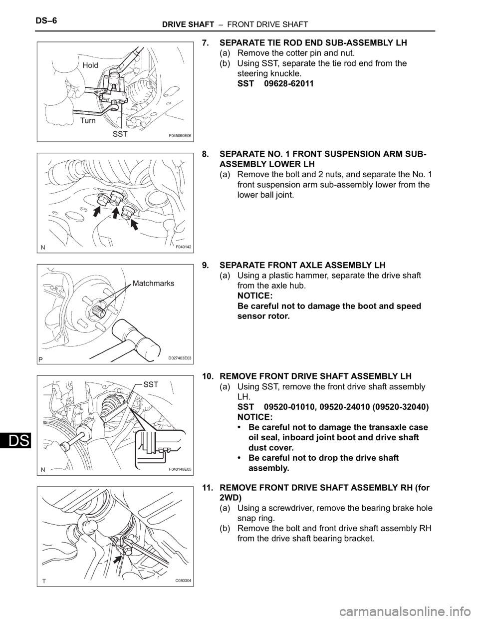
7. SEPARATE TIE ROD END SUB-ASSEMBLY LH
(a) Remove the cotter pin and nut.
(b) Using SST, separate the tie rod end from the
steering knuckle.
SST 09628-62011
8. SEPARATE NO. 1 FRONT SUSPENSION ARM SUB-
ASSEMBLY LOWER LH
(a) Remove the bolt and 2 nuts, and separate the No. 1
front suspension arm sub-assembly lower from the
lower ball joint.
9. SEPARATE FRONT AXLE ASSEMBLY LH
(a) Using a plastic hammer, separate the drive shaft
from the axle hub.
NOTICE:
Be careful not to damage the boot and speed
sensor rotor.
10. REMOVE FRONT DRIVE SHAFT ASSEMBLY LH
(a) Using SST, remove the front drive shaft assembly
LH.
SST 09520-01010, 09520-24010 (09520-32040)
NOTICE:
• Be careful not to damage the transaxle case
oil seal, inboard joint boot and drive shaft
dust cover.
• Be careful not to drop the drive shaft
assembly.
11. REMOVE FRONT DRIVE SHAFT ASSEMBLY RH (for
2WD)
(a) Using a screwdriver, remove the bearing brake hole
snap ring.
(b) Remove the bolt and front drive shaft assembly RH
from the drive shaft bearing bracket.
F045060E06
F040142
D027403E03
F040148E05
C080304
Page 112 of 3000
DRIVE SHAFT – FRONT DRIVE SHAFTDS–7
DS
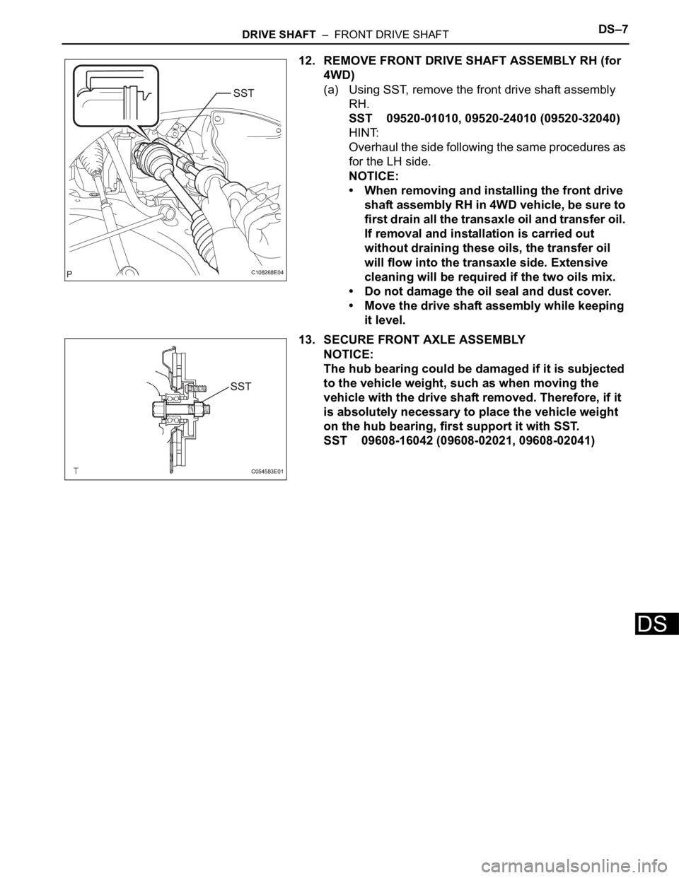
12. REMOVE FRONT DRIVE SHAFT ASSEMBLY RH (for
4WD)
(a) Using SST, remove the front drive shaft assembly
RH.
SST 09520-01010, 09520-24010 (09520-32040)
HINT:
Overhaul the side following the same procedures as
for the LH side.
NOTICE:
• When removing and installing the front drive
shaft assembly RH in 4WD vehicle, be sure to
first drain all the transaxle oil and transfer oil.
If removal and installation is carried out
without draining these oils, the transfer oil
will flow into the transaxle side. Extensive
cleaning will be required if the two oils mix.
• Do not damage the oil seal and dust cover.
• Move the drive shaft assembly while keeping
it level.
13. SECURE FRONT AXLE ASSEMBLY
NOTICE:
The hub bearing could be damaged if it is subjected
to the vehicle weight, such as when moving the
vehicle with the drive shaft removed. Therefore, if it
is absolutely necessary to place the vehicle weight
on the hub bearing, first support it with SST.
SST 09608-16042 (09608-02021, 09608-02041)
C108268E04
C054583E01
Page 132 of 3000
PREPARATION – U151E AUTOMATIC TRANSAXLEPP–25
PP
RECOMMENDED TOOLS
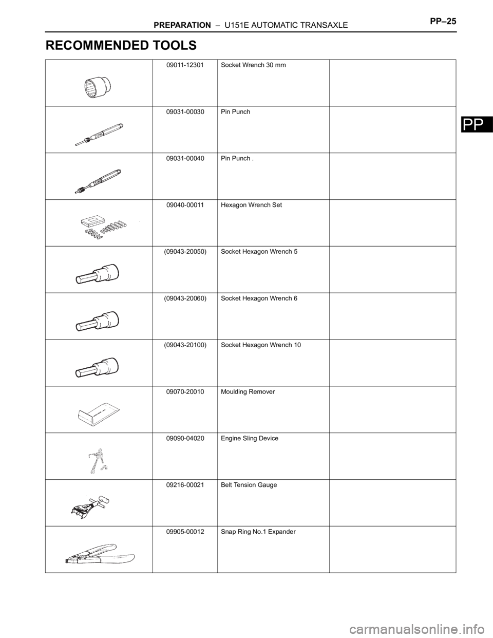
09011-12301 Socket Wrench 30 mm
09031-00030 Pin Punch
09031-00040 Pin Punch .
09040-00011 Hexagon Wrench Set
(09043-20050) Socket Hexagon Wrench 5
(09043-20060) Socket Hexagon Wrench 6
(09043-20100) Socket Hexagon Wrench 10
09070-20010 Moulding Remover
09090-04020 Engine Sling Device
09216-00021 Belt Tension Gauge
09905-00012 Snap Ring No.1 Expander