2007 TOYOTA SIENNA catalytic converter
[x] Cancel search: catalytic converterPage 58 of 3000

INTRODUCTION – TERMSIN–51
IN
IFI Indirect Fuel Injection Indirect Injection (IDL)
IFS Inertia Fuel-Shutoff -
ISC Idle Speed Control -
KS Knock Sensor Knock Sensor
MAF Mass Airflow Air Flow Meter
MAP Manifold Absolute Pressure Manifold Pressure Intake Vacuum
MC Mixture ControlElectric Bleed Air Control Valve (EBCV)
Mixture Control Valve (MCV)
Electric Air Control Valve (EACV)
MDP Manifold Differential Pressure -
MFI Multiport Fuel Injection Electronic Fuel Injection (EFI)
MIL Malfunction Indicator Light Check Engine Light
MST Manifold Surface Temperature -
MVZ Manifold Vacuum Zone -
NVRAM Non-Volatile Random Access Memory -
O2S Oxygen SensorOxygen Sensor, O
2 Sensor (O2S)
OBD On-Board Diagnostic On-Board Diagnostic System (OBD)
OC Oxidation Catalytic Converter Oxidation Catalytic Convert (OC), CCo
OL Open Loop Open Loop
PAIR Pulsed Secondary Air Injection Air Suction (AS)
PCM Powertrain Control Module -
PNP Park/Neutral Position -
PROM Programmable Read Only Memory -
PSP Power Steering Pressure -
PTOX Periodic Trap OxidizerDiesel Particulate Filter (DPF)
Diesel Particulate Trap (DPT)
RAM Random Access Memory Random Access Memory (RAM)
RM Relay Module -
ROM Read Only Memory Read Only Memory (ROM)
RPM Engine Speed Engine Speed
SC Supercharger Supercharger
SCB Supercharger Bypass E-ABV
SFI Sequential Multiport Fuel Injection Electronic Fuel Injection (EFI), Sequential Injection
SPL Smoke Puff Limiter -
SRI Service Reminder Indicator -
SRT System Readiness Test -
ST Scan Tool -
TB Throttle Body Throttle Body
TBI Throttle Body Fuel InjectionSingle Point Injection
Central Fuel Injection (Ci)
TC Turbocharger Turbocharger
TCC Torque Converter Clutch Torque Converter
TCM Transmission Control Module Transmission ECU, ECT ECU
TP Throttle Position Throttle Position
TR Transmission Range -
TVV Thermal Vacuum ValveBimetallic Vacuum Switching Valve (BVSV)
Thermostatic Vacuum Switching Valve (TVSV)
TWC Three-Way Catalytic ConverterThree-Way Catalytic (TWC)
Manifold Converter
CC
RO
SAE
ABBREVIATIONSSAE TERMSTOYOTA TERMS
( )-ABBREVIATIONS
Page 59 of 3000

IN–52INTRODUCTION – TERMS
IN
TWC+OC Three-Way + Oxidation Catalytic ConverterCCR + CCo
VAF Volume Airflow Air Flow Meter
VR Voltage Regulator Voltage Regulator
VSS Vehicle Speed Sensor Vehicle Speed Sensor
WOT Wide Open Throttle Full Throttle
WU-OC Warm Up Oxidation Catalytic Converter -
WU-TWC Warm Up Three-Way Catalytic Converter -
3GR Third Gear -
4GR Fourth Gear -SAE
ABBREVIATIONSSAE TERMSTOYOTA TERMS
( )-ABBREVIATIONS
Page 328 of 3000
ES–2602GR-FE ENGINE CONTROL SYSTEM – SFI SYSTEM
ES
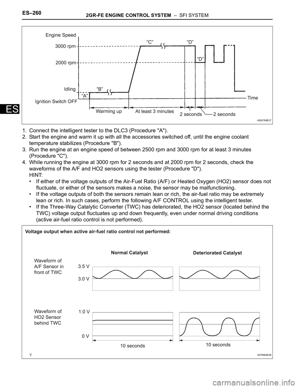
1. Connect the intelligent tester to the DLC3 (Procedure "A").
2. Start the engine and warm it up with all the accessories switched off, until the engine coolant
temperature stabilizes (Procedure "B").
3. Run the engine at an engine speed of between 2500 rpm and 3000 rpm for at least 3 minutes
(Procedure "C").
4. While running the engine at 3000 rpm for 2 seconds and at 2000 rpm for 2 seconds, check the
waveforms of the A/F and HO2 sensors using the tester (Procedure "D").
HINT:
• If either of the voltage outputs of the Air-Fuel Ratio (A/F) or Heated Oxygen (HO2) sensor does not
fluctuate, or either of the sensors makes a noise, the sensor may be malfunctioning.
• If the voltage outputs of both the sensors remain lean or rich, the air-fuel ratio may be extremely
lean or rich. In such cases, perform the following A/F CONTROL using the intelligent tester.
• If the Three-Way Catalytic Converter (TWC) has deteriorated, the HO2 sensor (located behind the
TWC) voltage output fluctuates up and down frequently, even under normal driving conditions
(active air-fuel ratio control is not performed).
A093766E27
A076893E08
Page 331 of 3000
2GR-FE ENGINE CONTROL SYSTEM – SFI SYSTEMES–263
ES
(b) Turn the ignition switch to the ON position and turn the
tester on.
(c) Select the following menu items: DIAGNOSIS /
ENHANCED OBD II / DTC INFO / CURRENT CODES.
(d) Read the DTCs.
Result
HINT:
If any DTCs other than P0420 or P0430 are output,
troubleshoot those DTCs first.
B
A
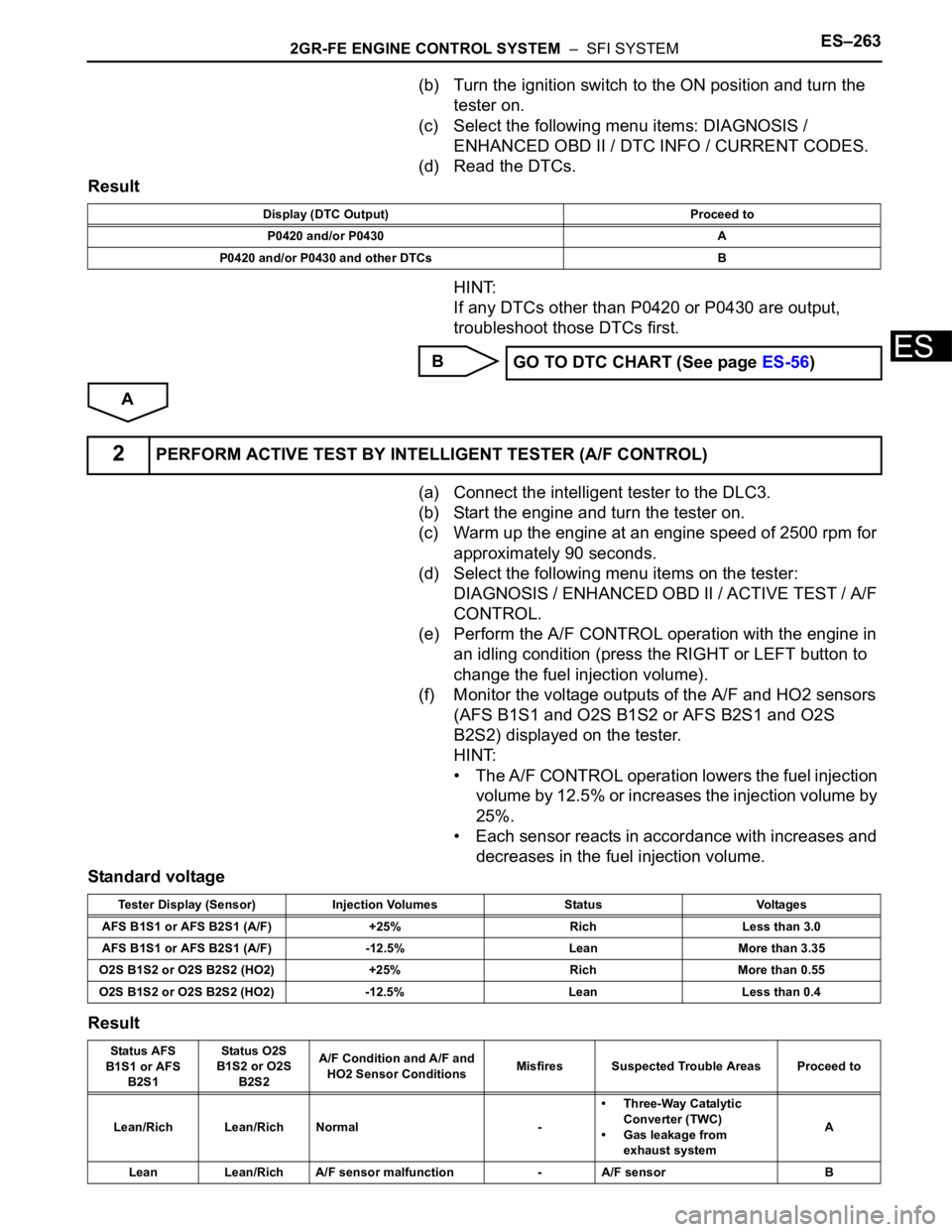
(a) Connect the intelligent tester to the DLC3.
(b) Start the engine and turn the tester on.
(c) Warm up the engine at an engine speed of 2500 rpm for
approximately 90 seconds.
(d) Select the following menu items on the tester:
DIAGNOSIS / ENHANCED OBD II / ACTIVE TEST / A/F
CONTROL.
(e) Perform the A/F CONTROL operation with the engine in
an idling condition (press the RIGHT or LEFT button to
change the fuel injection volume).
(f) Monitor the voltage outputs of the A/F and HO2 sensors
(AFS B1S1 and O2S B1S2 or AFS B2S1 and O2S
B2S2) displayed on the tester.
HINT:
• The A/F CONTROL operation lowers the fuel injection
volume by 12.5% or increases the injection volume by
25%.
• Each sensor reacts in accordance with increases and
decreases in the fuel injection volume.
Standard voltage
Result
Display (DTC Output) Proceed to
P0420 and/or P0430 A
P0420 and/or P0430 and other DTCs B
GO TO DTC CHART (See page ES-56)
2PERFORM ACTIVE TEST BY INTELLIGENT TESTER (A/F CONTROL)
Tester Display (Sensor) Injection Volumes Status Voltages
AFS B1S1 or AFS B2S1 (A/F) +25% Rich Less than 3.0
AFS B1S1 or AFS B2S1 (A/F) -12.5% Lean More than 3.35
O2S B1S2 or O2S B2S2 (HO2) +25% Rich More than 0.55
O2S B1S2 or O2S B2S2 (HO2) -12.5% Lean Less than 0.4
Status AFS
B1S1 or AFS
B2S1Status O2S
B1S2 or O2S
B2S2A/F Condition and A/F and
HO2 Sensor ConditionsMisfires Suspected Trouble Areas Proceed to
Lean/Rich Lean/Rich Normal -• Three-Way Catalytic
Converter (TWC)
• Gas leakage from
exhaust systemA
Lean Lean/Rich A/F sensor malfunction - A/F sensor B
Page 332 of 3000
ES–2642GR-FE ENGINE CONTROL SYSTEM – SFI SYSTEM
ES
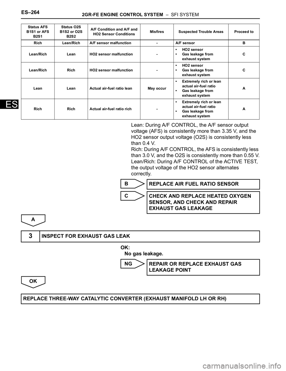
Lean: During A/F CONTROL, the A/F sensor output
voltage (AFS) is consistently more than 3.35 V, and the
HO2 sensor output voltage (O2S) is consistently less
than 0.4 V.
Rich: During A/F CONTROL, the AFS is consistently less
than 3.0 V, and the O2S is consistently more than 0.55 V.
Lean/Rich: During A/F CONTROL of the ACTIVE TEST,
the output voltage of the HO2 sensor alternates
correctly.
B
C
A
OK:
No gas leakage.
NG
OK
Rich Lean/Rich A/F sensor malfunction - A/F sensor B
Lean/Rich Lean HO2 sensor malfunction -• HO2 sensor
• Gas leakage from
exhaust systemC
Lean/Rich Rich HO2 sensor malfunction -• HO2 sensor
• Gas leakage from
exhaust systemC
Lean Lean Actual air-fuel ratio lean May occur• Extremely rich or lean
actual air-fuel ratio
• Gas leakage from
exhaust systemA
Rich Rich Actual air-fuel ratio rich -• Extremely rich or lean
actual air-fuel ratio
• Gas leakage from
exhaust systemA Status AFS
B1S1 or AFS
B2S1Status O2S
B1S2 or O2S
B2S2A/F Condition and A/F and
HO2 Sensor ConditionsMisfires Suspected Trouble Areas Proceed to
REPLACE AIR FUEL RATIO SENSOR
CHECK AND REPLACE HEATED OXYGEN
SENSOR, AND CHECK AND REPAIR
EXHAUST GAS LEAKAGE
3INSPECT FOR EXHAUST GAS LEAK
REPAIR OR REPLACE EXHAUST GAS
LEAKAGE POINT
REPLACE THREE-WAY CATALYTIC CONVERTER (EXHAUST MANIFOLD LH OR RH)
Page 415 of 3000
2GR-FE ENGINE CONTROL SYSTEM – SFI SYSTEMES–109
ES
HINT:
• Although the DTC titles say the oxygen sensor, these DTCs relate to the Air-Fuel Ratio (A/F) sensor.
• Sensor 1 refers to the sensor mounted in front of the Three-Way Catalytic Converter (TWC) and
located near the engine assembly.
DESCRIPTION
Refer to DTC P2195 (See page ES-355).
HINT:
• When any of these DTCs are set, the ECM enters fail-safe mode. The ECM turns off the A/F sensor
heater in fail-safe mode. Fail-safe mode continues until the ignition switch is turned off.
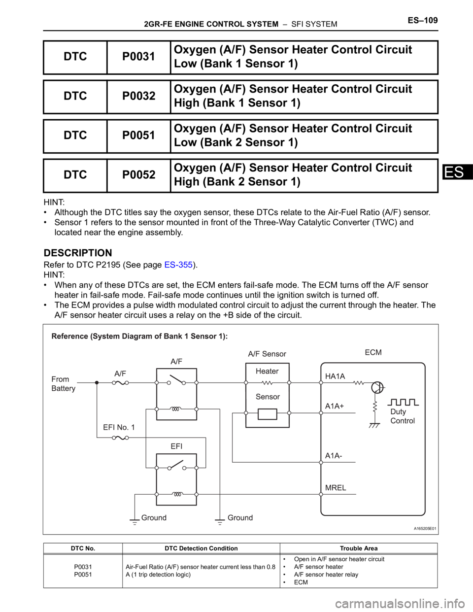
• The ECM provides a pulse width modulated control circuit to adjust the current through the heater. The
A/F sensor heater circuit uses a relay on the +B side of the circuit.
DTC P0031Oxygen (A/F) Sensor Heater Control Circuit
Low (Bank 1 Sensor 1)
DTC P0032Oxygen (A/F) Sensor Heater Control Circuit
High (Bank 1 Sensor 1)
DTC P0051Oxygen (A/F) Sensor Heater Control Circuit
Low (Bank 2 Sensor 1)
DTC P0052Oxygen (A/F) Sensor Heater Control Circuit
High (Bank 2 Sensor 1)
DTC No. DTC Detection Condition Trouble Area
P0031
P0051Air-Fuel Ratio (A/F) sensor heater current less than 0.8
A (1 trip detection logic)• Open in A/F sensor heater circuit
• A/F sensor heater
• A/F sensor heater relay
•ECM
A165205E01
Page 416 of 3000

ES–1102GR-FE ENGINE CONTROL SYSTEM – SFI SYSTEM
ES
HINT:
• Bank 1 refers to the bank that includes cylinder No. 1.
• Bank 2 refers to the bank that does not include cylinder No. 1.
• Sensor 1 refers to the closest sensor to the engine assembly.
• Sensor 2 refers to the furthest sensor away from the engine assembly.
MONITOR DESCRIPTION
The ECM uses information from the Air-Fuel Ratio (A/F) sensor to regulate the air-fuel ratio and keep it
close to the stoichiometric level. This maximizes the ability of the Three-Way Catalytic Converter (TWC) to
purify the exhaust gas.
The A/F sensor detects oxygen levels in the exhaust gas and transmits the information to the ECM. The
inner surface of the sensor element is exposed to the outside air. The outer surface of the sensor element
is exposed to the exhaust gas. The sensor element is made of platinum coated zirconia and includes an
integrated heating element.
The zirconia element generates small voltage when there is a large difference in the oxygen
concentrations between the exhaust gas and outside air. The platinum coating amplifies this voltage
generation.
The A/F sensor is more efficient when heated. When the exhaust gas temperature is low, the sensor
cannot generate useful voltage signals without supplementary heating. The ECM regulates the
supplementary heating using a duty-cycle approach to adjust the average current in the sensor heater
element. If the heater current is outside the normal range, the signal transmitted by the A/F sensor will be
inaccurate, as a result, the ECM will be unable to regulate air-fuel ratio properly.
When the current in the A/F sensor heater is outside the normal operating range, the ECM interprets this
as a malfunction in the sensor heater and sets a DTC.
Example:
The ECM sets DTC P0032 or P0052 when the current in the A/F sensor heater is more than 10 A.
Conversely, when the heater current is less than 0.8 A, DTC P0031 or P0051 is set.
MONITOR STRATEGY
TYPICAL ENABLING CONDITIONS
All:
P0031 and P0051:
P0032
P0052Air-Fuel Ratio (A/F) sensor heater current more than 10
A (1 trip detection logic)• Short in A/F sensor heater circuit
• A/F sensor heater
• A/F sensor heater relay
•ECM
Related DTCsP0031: A/F sensor heater (Bank 1) range check (Low current)
P0032: A/F sensor heater (Bank 1) range check (High current)
P0051: A/F sensor heater (Bank 2) range check (Low current)
P0052: A/F sensor heater (Bank 2) range check (High current)
Required sensors / components (Main) A/F sensor heater
Required sensors / components (Related) -
Frequency of operation Continuous
Duration 10 seconds
MIL operation Immediate
Sequence operation None
The monitor will run whenever these DTCs are not
presentNone
Battery voltage 10.5 V or more
Heater ON duty ratio 50% or moreDTC No. DTC Detection Condition Trouble Area
Page 423 of 3000
2GR-FE ENGINE CONTROL SYSTEM – SFI SYSTEMES–117
ES
HINT:
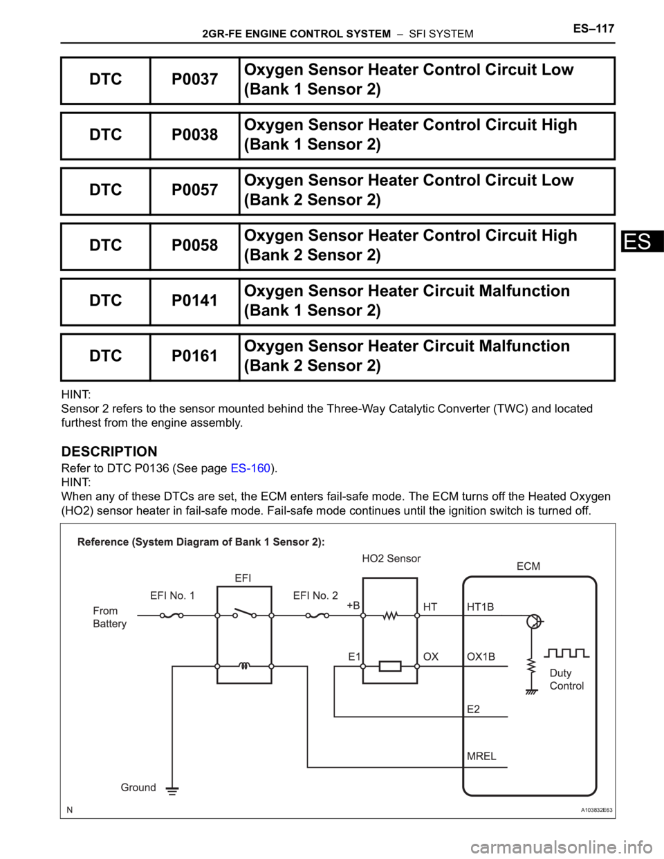
Sensor 2 refers to the sensor mounted behind the Three-Way Catalytic Converter (TWC) and located
furthest from the engine assembly.
DESCRIPTION
Refer to DTC P0136 (See page ES-160).
HINT:
When any of these DTCs are set, the ECM enters fail-safe mode. The ECM turns off the Heated Oxygen
(HO2) sensor heater in fail-safe mode. Fail-safe mode continues until the ignition switch is turned off.
DTC P0037Oxygen Sensor Heater Control Circuit Low
(Bank 1 Sensor 2)
DTC P0038Oxygen Sensor Heater Control Circuit High
(Bank 1 Sensor 2)
DTC P0057Oxygen Sensor Heater Control Circuit Low
(Bank 2 Sensor 2)
DTC P0058Oxygen Sensor Heater Control Circuit High
(Bank 2 Sensor 2)
DTC P0141Oxygen Sensor Heater Circuit Malfunction
(Bank 1 Sensor 2)
DTC P0161Oxygen Sensor Heater Circuit Malfunction
(Bank 2 Sensor 2)
A103832E63