2007 TOYOTA SIENNA drain bolt
[x] Cancel search: drain boltPage 16 of 3000

SS–30SERVICE SPECIFICATIONS – U151E AUTOMATIC TRANSAXLE
SS
TORQUE SPECIFICATIONS
Part Tightened N*m kgf*cm ft*lbf
Park/neutral position switch Nut 6.9 70 61 in.*lbf
Bolt 5.4 55 48 in.*lbf
Control shaft lever x Control shaft 13 130 9
Shift control cable x Control shaft lever 13 130 9
Transaxle housing x Engine block A bolt 64 653 47
B bolt 46 470 34
C bolt 43 439 32
Torque converter clutch x Drive plate 41 413 35
Flywheel housing under cover x Automatic transaxle 7.8 80 69 in.*lbf
Engine mounting bracket FR x Transaxle 64 653 47
Oil filler tube x Transaxle5.5 56 49 in.*lbf
Control cable bracket No. 1 x Transaxle 12 122 9
Control cable bracket No. 2 x Transaxle 12 122 9
Oil cooler tube clamp x Control cable bracket 5.5 56 49 in.*lbf
Oil cooler inlet tube x Transaxle27 275 20
Oil cooler outlet tube x Transaxle 27 275 20
Starter x Transaxle37 377 27
Starter wire x Starter9.8 100 87 in.*lbf
Wire harness x Transaxle13 133 10
Wire harness clamp x Transaxle8.4 86 74 in.*lbf
Speed sensor (NC) x Transaxle11 11 5 8
Speed sensor (NT) x Transaxle11 11 2 8
Air cleaner x Air cleaner hose5.0 51 44 in.*lbf
Drain plug x Oil pan49 500 36
Transmission wire x Transaxle5.4 55 48 in.*lbf
ATF temperature sensor x Valve body 6.6 67 58 in.*lbf
Oil pan x Transaxle7.8 80 69 in.*lbf
Solenoid valve x Valve body A B bolt 11 110 8
C D bolt 6.6 67 58 in.*lbf
Valve body x Transaxle11 11 0 8
Oil strainer x Valve body11 11 0 8
Floor shift assembly x Body21 214 15
Control cable x Body12 122 9
Engine mount bracket RR x Transfer stiffener plate RH 34 350 25
Oil cooler assembly x Body Nut
7.0 71 62 in.*lbf
bolt
Differential gear lube apply tube x Transaxle housing 9.8 100 87 in.*lbf
Front planetary gear lock nut
210 to 3502,141 to
3,569155 to 258
Brake apply tube clamp x Transaxle case 5.4 55 48 in.*lbf
Transaxle case No. 1 plug x Transaxle rear cover 7.4 75 65 in.*lbf
Transaxle rear cover x Transaxle case Bolt A 19 190 14
Other bolt 25 250 18
Pawl shaft clamp x Transaxle case 9.8 100 87 in.*lbf
Oil pump assembly x Transaxle case 22 226 16
Page 17 of 3000

SERVICE SPECIFICATIONS – U151E AUTOMATIC TRANSAXLESS–31
SS
Transaxle housing x Transaxle case Bolt A 22 225 16
Bolt B 29 300 22
Bolt C 29 295 21
Bolt D 22 226 16
Automatic transmission case plug x Transaxle housing 7.4 75 65 in.*lbf
Automatic transmission case plug x Transaxle case 7.4 75 65 in.*lbf
Parking lock pawl bracket x Transaxle case 20 205 15
Manual detent spring x Transaxle case Bolt A 20 205 15
Bolt B 12 120 9
Transmission wire x Transaxle housing 5.4 55 48 in.*lbf
Transmission valve body x Transaxle case 11 110 8
ATF temperature sensor clamp x Transmission valve body 6.6 67 58 in.*lbf
Valve body oil strainer assembly x Transmission valve body 11 1108
Automatic transaxle oil pan sub-assembly x Transaxle case 7.8 80 69 in.*lbf
Drain plug x Automatic transaxle oil pan sub-assembly 49 500 36
Speed sensor x Transaxle case11 11 5 8
Oil cooler tube union x Transaxle case Union 27 276 20
Elbow 27 276 20
Park/neutral start switch x nut6.9 70 61 in.*lbf
Park/neutral start switch x Bolt5.4 55 48 in.*lbf
Park/neutral start switch x Control shaft lever 13 130 9
Speedometer driven hole cover sub-assembly x Transaxle case 6.9 7061
Oil pump body x Stator shaft assembly 9.8 100 87 in.*lbf
Line pressure control solenoid assembly x Transmission valve body assembly 6.6 67 58 in.*lbf
Shift solenoid valve SL1 x Transmission valve body assembly 6.6 67 58 in.*lbf
Shift solenoid valve SL2 x Transmission valve body assembly 10.811 0 8
Shift solenoid valve SL3 x Transmission valve body assembly 6.6 67 58 in.*lbf
Shift solenoid valve S4 x Transmission valve body assembly 10.8 110 8
Shift solenoid valve DSL x Transmission valve body assembly 10.811 0 8
Front differential case x Front differential ring gear 95.1 970 70Part Tightened N*m kgf*cm ft*lbf
Page 25 of 3000

EM–262GR-FE ENGINE MECHANICAL – ENGINE ASSEMBLY
EM
REMOVAL
1. DISCHARGE FUEL SYSTEM PRESSURE (See page
FU-13)
2. DISCHARGE REFRIGERANT FROM
REFRIGERATION SYSTEM (See page AC-172)
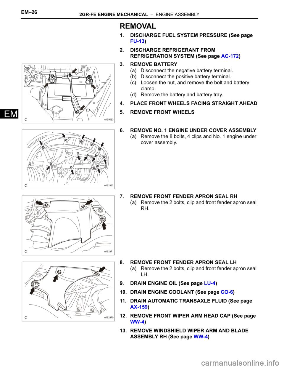
3. REMOVE BATTERY
(a) Disconnect the negative battery terminal.
(b) Disconnect the positive battery terminal.
(c) Loosen the nut, and remove the bolt and battery
clamp.
(d) Remove the battery and battery tray.
4. PLACE FRONT WHEELS FACING STRAIGHT AHEAD
5. REMOVE FRONT WHEELS
6. REMOVE NO. 1 ENGINE UNDER COVER ASSEMBLY
(a) Remove the 8 bolts, 4 clips and No. 1 engine under
cover assembly.
7. REMOVE FRONT FENDER APRON SEAL RH
(a) Remove the 2 bolts, clip and front fender apron seal
RH.
8. REMOVE FRONT FENDER APRON SEAL LH
(a) Remove the 2 bolts, clip and front fender apron seal
LH.
9. DRAIN ENGINE OIL (See page LU-4)
10. DRAIN ENGINE COOLANT (See page CO-6)
11. DRAIN AUTOMATIC TRANSAXLE FLUID (See page
AX-159)
12. REMOVE FRONT WIPER ARM HEAD CAP (See page
WW-4)
13. REMOVE WINDSHIELD WIPER ARM AND BLADE
ASSEMBLY RH (See page WW-4)
A155033
A162362
A162371
A162370
Page 107 of 3000

TRANSFER – TRANSFER ASSEMBLYTF–9
TF
INSTALLATION
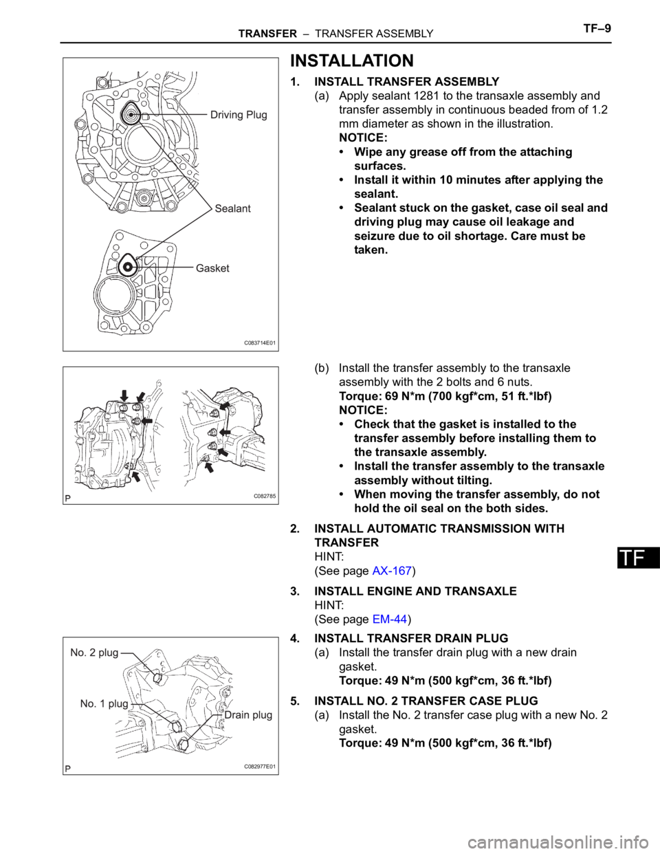
1. INSTALL TRANSFER ASSEMBLY
(a) Apply sealant 1281 to the transaxle assembly and
transfer assembly in continuous beaded from of 1.2
mm diameter as shown in the illustration.
NOTICE:
• Wipe any grease off from the attaching
surfaces.
• Install it within 10 minutes after applying the
sealant.
• Sealant stuck on the gasket, case oil seal and
driving plug may cause oil leakage and
seizure due to oil shortage. Care must be
taken.
(b) Install the transfer assembly to the transaxle
assembly with the 2 bolts and 6 nuts.
Torque: 69 N*m (700 kgf*cm, 51 ft.*lbf)
NOTICE:
• Check that the gasket is installed to the
transfer assembly before installing them to
the transaxle assembly.
• Install the transfer assembly to the transaxle
assembly without tilting.
• When moving the transfer assembly, do not
hold the oil seal on the both sides.
2. INSTALL AUTOMATIC TRANSMISSION WITH
TRANSFER
HINT:
(See page AX-167)
3. INSTALL ENGINE AND TRANSAXLE
HINT:
(See page EM-44)
4. INSTALL TRANSFER DRAIN PLUG
(a) Install the transfer drain plug with a new drain
gasket.
Torque: 49 N*m (500 kgf*cm, 36 ft.*lbf)
5. INSTALL NO. 2 TRANSFER CASE PLUG
(a) Install the No. 2 transfer case plug with a new No. 2
gasket.
Torque: 49 N*m (500 kgf*cm, 36 ft.*lbf)
C083714E01
C082785
C082977E01
Page 110 of 3000

DRIVE SHAFT – FRONT DRIVE SHAFTDS–5
DS
REMOVAL
1. DRAIN AUTOMATIC TRANSAXLE FLUID
(a) Remove the drain plug, gasket and drain ATF.
(b) Install a new gasket and the drain plug.
Torque: 49 N*m (500 kgf*cm, 36 ft.*lbf)
2. DRAIN TRANSFER OIL (for 4WD)
HINT:
(See page TF-8)
3. REMOVE FRONT WHEEL
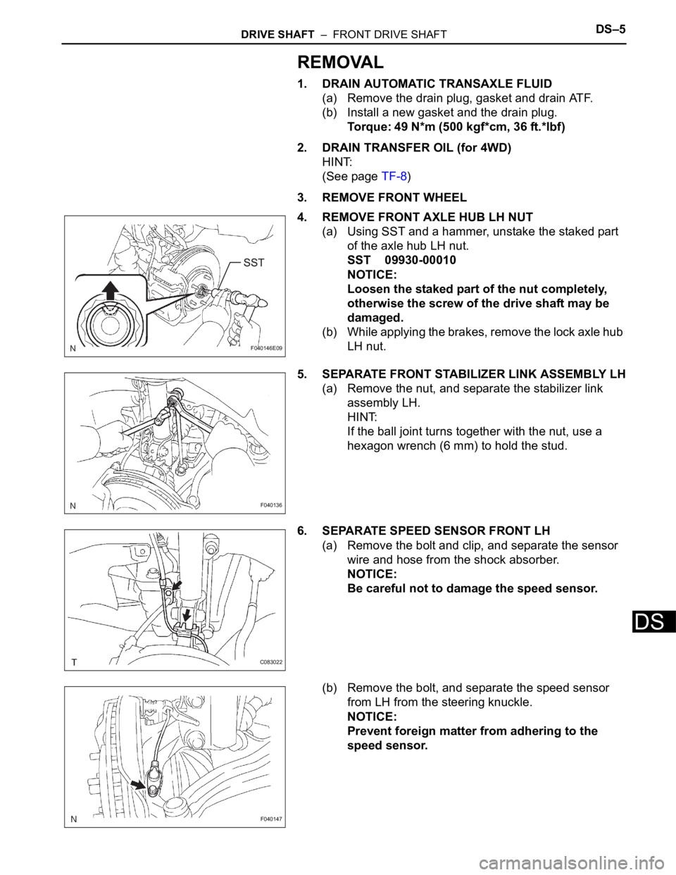
4. REMOVE FRONT AXLE HUB LH NUT
(a) Using SST and a hammer, unstake the staked part
of the axle hub LH nut.
SST 09930-00010
NOTICE:
Loosen the staked part of the nut completely,
otherwise the screw of the drive shaft may be
damaged.
(b) While applying the brakes, remove the lock axle hub
LH nut.
5. SEPARATE FRONT STABILIZER LINK ASSEMBLY LH
(a) Remove the nut, and separate the stabilizer link
assembly LH.
HINT:
If the ball joint turns together with the nut, use a
hexagon wrench (6 mm) to hold the stud.
6. SEPARATE SPEED SENSOR FRONT LH
(a) Remove the bolt and clip, and separate the sensor
wire and hose from the shock absorber.
NOTICE:
Be careful not to damage the speed sensor.
(b) Remove the bolt, and separate the speed sensor
from LH from the steering knuckle.
NOTICE:
Prevent foreign matter from adhering to the
speed sensor.
F040146E09
F040136
C083022
F040147
Page 191 of 3000

POWER STEERING – VANE PUMPPS–9
PS
REMOVAL
1. DRAIN POWER STEERING FLUID
2. REMOVE FRONT WHEEL RH
3. REMOVE FRONT FENDER APRON SEAL RH (See
page EM-26)
4. REMOVE FAN AND GENERATOR V BELT (See page
EM-6)
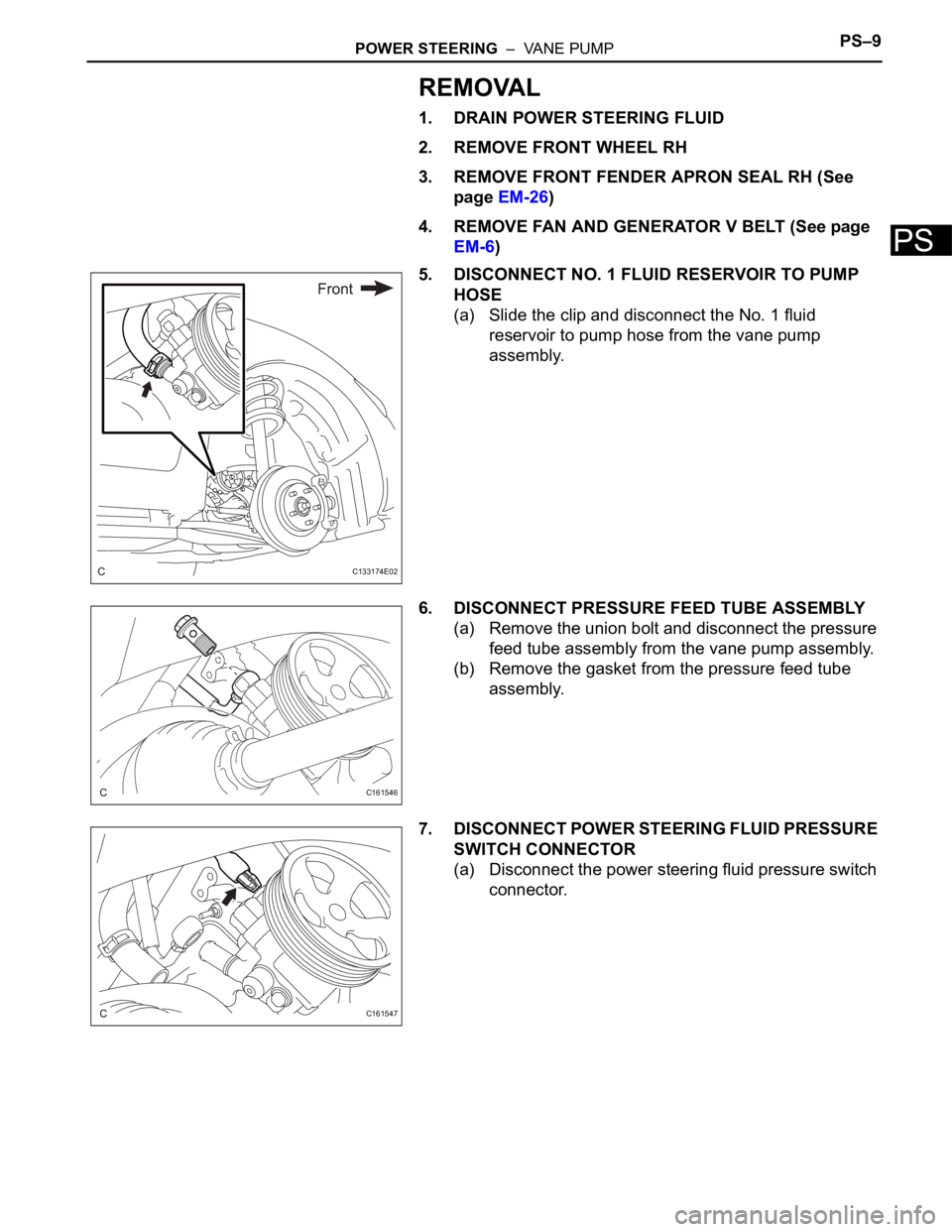
5. DISCONNECT NO. 1 FLUID RESERVOIR TO PUMP
HOSE
(a) Slide the clip and disconnect the No. 1 fluid
reservoir to pump hose from the vane pump
assembly.
6. DISCONNECT PRESSURE FEED TUBE ASSEMBLY
(a) Remove the union bolt and disconnect the pressure
feed tube assembly from the vane pump assembly.
(b) Remove the gasket from the pressure feed tube
assembly.
7. DISCONNECT POWER STEERING FLUID PRESSURE
SWITCH CONNECTOR
(a) Disconnect the power steering fluid pressure switch
connector.
C133174E02
C161546
C161547
Page 199 of 3000

SS–12SERVICE SPECIFICATIONS – 2GR-FE ENGINE MECHANICAL
SS
Oil strainer stud bolt x Timing chain cover sub-assembly 4.0 41 35 in.*lbf
Oil strainer sub-assembly x Cylinder block and timing chain cover sub-
assembly10 102 7
Oil pan sub-assembly x Cylinder block and
timing chain cover sub-assembly
bolt A 10 102 7
except bolt A 21 214 15
Oil pan sub-assembly No. 2 x Oil pan sub-assembly 10 102 7
Oil pan drain plug x Oil pan sub-assembly No. 2 40 408 30
Crankshaft pulley x Crankshaft 250 2,550 184
Cylinder head cover sub-assembly x Cylinder
head sub-assembly RH
bolt A 21 214 15
except bolt A 10 102 7
Cylinder head cover sub-assembly LH x
Cylinder head sub-assembly LH
bolt A 21 214 15
except bolt A 10 102 7
Water outlet x Cylinder head sub-assembly bolt 10 102 7
nut 10 103 7
Water inlet housing set nut 10 102 7
Stud bolt x Water inlet housing 4.0 41 35 in.*lbf
Water inlet set bolt and nut 10 102 7
Stud bolt x No. 1 oil cooler bracket 10 102 7
Oil cooler pipe x No. 1 oil cooler bracket bolt 21 214 16
nut 21 214 16
No. 1 oil cooler bracket w/ Oil cooler pipe x Oil
pan sub-assembly and Cylinder block sub-
assemblybolt 21 214 16
nut 21 214 16
No. 1 oil cooler bracket x Oil cooler assembly 68 693 50
Water by-pass hoses x Clamp 10 102 7
Oil filter cap x Oil pan sub-assembly 25 255 18
Oil filter cap x Drain plug 13 127 9
Camshaft position sensor x Cylinder head cover sub-assembly 10 1027
Ventilation valve x Cylinder head cover sub-assembly LH 27 275 20
Oil pipe union x Cylinder block sub-assembly 65 663 48
Oil pipe union x Cylinder head cover sub-assembly 65 663 48
Oil pipe x Cylinder head sub-assembly 10 102 7
Crankshaft position sensor x Cylinder block sub-assembly 10 102 7
Camshaft timing oil control valve assembly x Cylinder head cover sub-
assembly10 102 7
Cylinder block water drain cock sub-assembly x Cylinder block sub-
assembly25 255 18
Drain cock sub-assembly x Water inlet housing 30 306 22
Water drain cock plug x Water drain cock sub-assembly 13 130 9
Drain cock plug x Drain cock assembly 13 130 9
Spark plug x Cylinder head sub-assembly 18 184 13
Stud bolt x Cylinder head sub-assembly For A and B bolts 10 102 7
For C bolts 4.0 41 35 in.*lbf
No. 1 straight screw plug x Cylinder head sub-assembly 44 449 32
No. 2 straight screw plug x Cylinder head sub-assembly 80 816 59Part Tightened N*m kgf*cm ft.*lbf
Page 214 of 3000

SERVICE SPECIFICATIONS – U151F AUTOMATIC TRANSAXLESS–37
SS
TORQUE SPECIFICATIONS
Part Tightened N*m kgf*cm ft*lbf
Park/neutral position switch Nut 6.9 70 61 in.*lbf
Bolt 5.4 55 48 in.*lbf
Control shaft lever x Control shaft 13 130 9
Shift control cable x Control shaft lever 13 130 9
Transaxle housing x Engine block A bolt 64 653 47
B bolt 46 470 34
C bolt 43 439 32
Torque converter clutch x Drive plate 41 413 30
Flywheel housing under cover x Automatic transaxle 7.8 80 69 in.*lbf
Engine mounting bracket FR x Transaxle 64 653 47
Oil filler tube x Transaxle5.5 56 49 in.*lbf
Control cable bracket No. 1 x Transaxle 12 122 9
Control cable bracket No. 2 x Transaxle 12 122 9
Oil cooler tube clamp x Control cable bracket 5.5 56 49 in.*lbf
Oil cooler inlet tube x Transaxle27 275 20
Oil cooler outlet tube x Transaxle 27 275 20
Starter x Transaxle37 377 27
Starter wire x Starter9.8 100 87 in.*lbf
Wire harness x Transaxle13 133 10
Wire harness clamp x Transaxle8.4 86 74 in.*lbf
Speed sensor (NC) x Transaxle11 11 5 8
Speed sensor (NT) x Transaxle11 11 2 8
Air cleaner x Air cleaner hose5.0 51 44 in.*lbf
Drain plug x Oil pan49 500 36
Transmission wire x Transaxle5.4 55 48 in.*lbf
ATF temperature sensor x Valve body 6.6 67 58 in.*lbf
Oil pan x Transaxle7.8 80 69 in.*lbf
Solenoid valve x Valve body A B bolt 11 110 8
C D bolt 6.6 67 58 in.*lbf
Valve body x Transaxle11 11 0 8
Oil strainer x Valve body11 11 0 8
Floor shift assembly x Body21 214 15
Control cable x Body12 122 9
Transfer x Transaxle69 700 51
Transfer x Transfer stiffener plate RH 34 350 25
Engine mount bracket RR x Transfer stiffener plate RH 34 350 25
Oil cooler assembly x Body Nut
7.0 71 62 in.*lbf
bolt
Differential gear lube apply tube x Transaxle housing 9.8 100 87 in.*lbf
Front planetary gear lock nut
210 to 3502,141 to
3,569155 to 258
Brake apply tube clamp x Transaxle case 5.4 55 48 in.*lbf
Transaxle case No. 1 plug x Transaxle rear cover 7.4 75 65 in.*lbf
Transaxle rear cover x Transaxle case Bolt A 19 190 14
Other bolt 25 250 18
Pawl shaft clamp x Transaxle case 9.8 100 87 in.*lbf
Oil pump assembly x Transaxle case 22 226 16