Page 58 of 3000

INTRODUCTION – TERMSIN–51
IN
IFI Indirect Fuel Injection Indirect Injection (IDL)
IFS Inertia Fuel-Shutoff -
ISC Idle Speed Control -
KS Knock Sensor Knock Sensor
MAF Mass Airflow Air Flow Meter
MAP Manifold Absolute Pressure Manifold Pressure Intake Vacuum
MC Mixture ControlElectric Bleed Air Control Valve (EBCV)
Mixture Control Valve (MCV)
Electric Air Control Valve (EACV)
MDP Manifold Differential Pressure -
MFI Multiport Fuel Injection Electronic Fuel Injection (EFI)
MIL Malfunction Indicator Light Check Engine Light
MST Manifold Surface Temperature -
MVZ Manifold Vacuum Zone -
NVRAM Non-Volatile Random Access Memory -
O2S Oxygen SensorOxygen Sensor, O
2 Sensor (O2S)
OBD On-Board Diagnostic On-Board Diagnostic System (OBD)
OC Oxidation Catalytic Converter Oxidation Catalytic Convert (OC), CCo
OL Open Loop Open Loop
PAIR Pulsed Secondary Air Injection Air Suction (AS)
PCM Powertrain Control Module -
PNP Park/Neutral Position -
PROM Programmable Read Only Memory -
PSP Power Steering Pressure -
PTOX Periodic Trap OxidizerDiesel Particulate Filter (DPF)
Diesel Particulate Trap (DPT)
RAM Random Access Memory Random Access Memory (RAM)
RM Relay Module -
ROM Read Only Memory Read Only Memory (ROM)
RPM Engine Speed Engine Speed
SC Supercharger Supercharger
SCB Supercharger Bypass E-ABV
SFI Sequential Multiport Fuel Injection Electronic Fuel Injection (EFI), Sequential Injection
SPL Smoke Puff Limiter -
SRI Service Reminder Indicator -
SRT System Readiness Test -
ST Scan Tool -
TB Throttle Body Throttle Body
TBI Throttle Body Fuel InjectionSingle Point Injection
Central Fuel Injection (Ci)
TC Turbocharger Turbocharger
TCC Torque Converter Clutch Torque Converter
TCM Transmission Control Module Transmission ECU, ECT ECU
TP Throttle Position Throttle Position
TR Transmission Range -
TVV Thermal Vacuum ValveBimetallic Vacuum Switching Valve (BVSV)
Thermostatic Vacuum Switching Valve (TVSV)
TWC Three-Way Catalytic ConverterThree-Way Catalytic (TWC)
Manifold Converter
CC
RO
SAE
ABBREVIATIONSSAE TERMSTOYOTA TERMS
( )-ABBREVIATIONS
Page 430 of 3000

ES–1242GR-FE ENGINE CONTROL SYSTEM – SFI SYSTEM
ES
DESCRIPTION
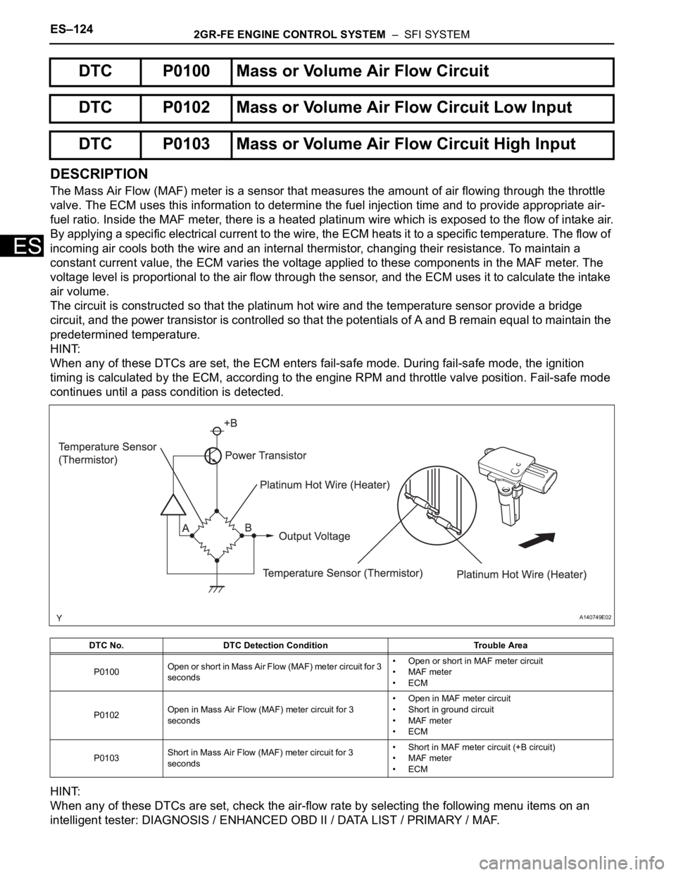
The Mass Air Flow (MAF) meter is a sensor that measures the amount of air flowing through the throttle
valve. The ECM uses this information to determine the fuel injection time and to provide appropriate air-
fuel ratio. Inside the MAF meter, there is a heated platinum wire which is exposed to the flow of intake air.
By applying a specific electrical current to the wire, the ECM heats it to a specific temperature. The flow of
incoming air cools both the wire and an internal thermistor, changing their resistance. To maintain a
constant current value, the ECM varies the voltage applied to these components in the MAF meter. The
voltage level is proportional to the air flow through the sensor, and the ECM uses it to calculate the intake
air volume.
The circuit is constructed so that the platinum hot wire and the temperature sensor provide a bridge
circuit, and the power transistor is controlled so that the potentials of A and B remain equal to maintain the
predetermined temperature.
HINT:
When any of these DTCs are set, the ECM enters fail-safe mode. During fail-safe mode, the ignition
timing is calculated by the ECM, according to the engine RPM and throttle valve position. Fail-safe mode
continues until a pass condition is detected.
HINT:
When any of these DTCs are set, check the air-flow rate by selecting the following menu items on an
intelligent tester: DIAGNOSIS / ENHANCED OBD II / DATA LIST / PRIMARY / MAF.
DTC P0100 Mass or Volume Air Flow Circuit
DTC P0102 Mass or Volume Air Flow Circuit Low Input
DTC P0103 Mass or Volume Air Flow Circuit High Input
DTC No. DTC Detection Condition Trouble Area
P0100Open or short in Mass Air Flow (MAF) meter circuit for 3
seconds• Open or short in MAF meter circuit
• MAF meter
•ECM
P0102Open in Mass Air Flow (MAF) meter circuit for 3
seconds• Open in MAF meter circuit
• Short in ground circuit
• MAF meter
•ECM
P0103Short in Mass Air Flow (MAF) meter circuit for 3
seconds• Short in MAF meter circuit (+B circuit)
• MAF meter
•ECM
A140749E02
Page 729 of 3000

2GR-FE ENGINE CONTROL SYSTEM – SFI SYSTEMES–443
ES
(a) Remove the throttle body (See page ES-493).
(b) Check that the EVAP purge port of the throttle body is
not clogged. If necessary, replace the throttle body.
NEXT
(a) Replace the ECM (See page ES-498).
NEXT
(a) Repair the malfunctioning areas indicated by the DTCs
that had been confirmed when the vehicle was brought
in.
NEXT
NOTICE:
• In the EVAP SYSTEM CHECK (AUTO OPERATION), the
series of 5 EVAP SYSTEM CHECK steps are performed
automatically. It takes a maximum of approximately 18
minutes.
• Do not perform the EVAP SYSTEM CHECK when the
fuel tank is more than 90% full because the cut-off
valve may be closed, making the leak check of the fuel
tank unavailable.
• Do not run the engine in this step.
• When the temperature of the fuel is 35
C (95F) or
more, a large amount of vapor forms and any check
results become inaccurate. When performing an EVAP
SYSTEM CHECK, keep the temperature below 35
C
(95
F).
(a) Clear the DTCs (See page ES-39).
(b) On the intelligent tester, select the following menu items:
DIAGNOSIS / ENHANCED OBD II / SYSTEM CHECK /
EVAP SYS CHECK / AUTO OPERATION.
(c) After the SYSTEM CHECK is completed, check for
pending DTCs by selecting the following menu items:
DIAGNOSIS / ENHANCED OBD II / DTC INFO /
PENDING CODES.
HINT:
If no pending DTC is found, the repair has been
successfully completed.
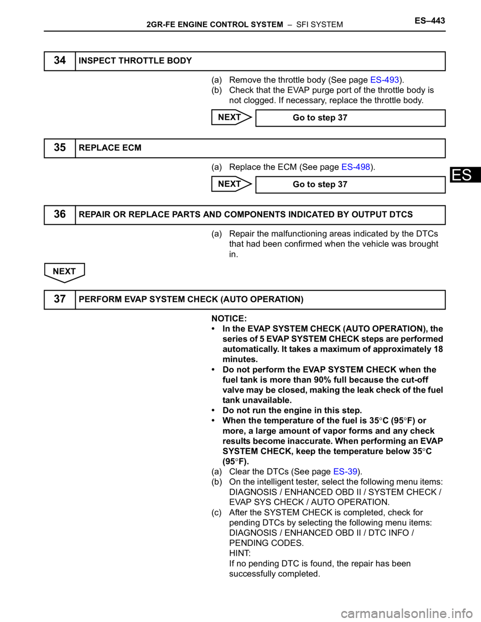
34INSPECT THROTTLE BODY
Go to step 37
35REPLACE ECM
Go to step 37
36REPAIR OR REPLACE PARTS AND COMPONENTS INDICATED BY OUTPUT DTCS
37PERFORM EVAP SYSTEM CHECK (AUTO OPERATION)