2007 TOYOTA SIENNA height
[x] Cancel search: heightPage 906 of 3000
2GR-FE ENGINE MECHANICAL – ENGINE UNITEM–101
EM
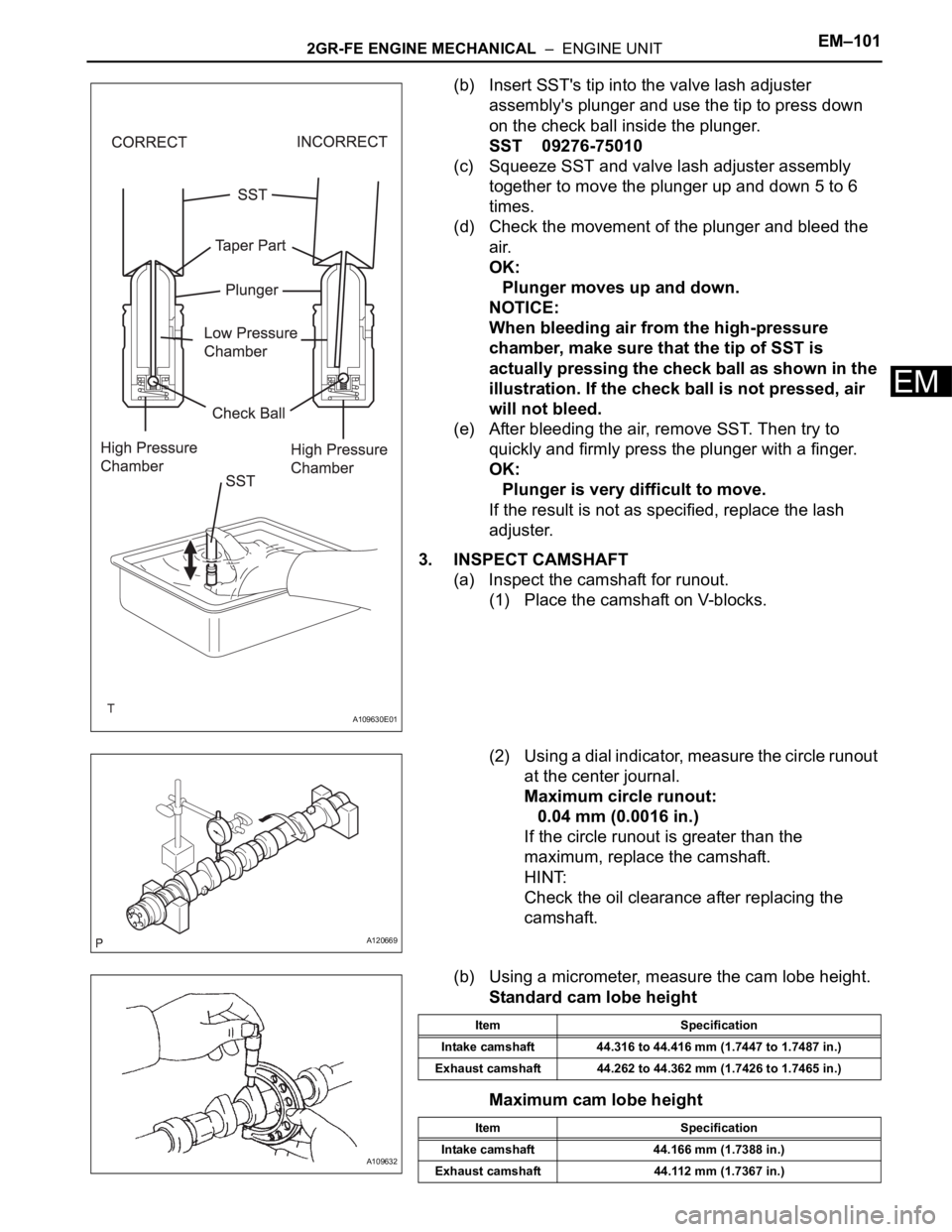
(b) Insert SST's tip into the valve lash adjuster
assembly's plunger and use the tip to press down
on the check ball inside the plunger.
SST 09276-75010
(c) Squeeze SST and valve lash adjuster assembly
together to move the plunger up and down 5 to 6
times.
(d) Check the movement of the plunger and bleed the
air.
OK:
Plunger moves up and down.
NOTICE:
When bleeding air from the high-pressure
chamber, make sure that the tip of SST is
actually pressing the check ball as shown in the
illustration. If the check ball is not pressed, air
will not bleed.
(e) After bleeding the air, remove SST. Then try to
quickly and firmly press the plunger with a finger.
OK:
Plunger is very difficult to move.
If the result is not as specified, replace the lash
adjuster.
3. INSPECT CAMSHAFT
(a) Inspect the camshaft for runout.
(1) Place the camshaft on V-blocks.
(2) Using a dial indicator, measure the circle runout
at the center journal.
Maximum circle runout:
0.04 mm (0.0016 in.)
If the circle runout is greater than the
maximum, replace the camshaft.
HINT:
Check the oil clearance after replacing the
camshaft.
(b) Using a micrometer, measure the cam lobe height.
Standard cam lobe height
Maximum cam lobe height
A109630E01
A120669
A109632
Item Specification
Intake camshaft 44.316 to 44.416 mm (1.7447 to 1.7487 in.)
Exhaust camshaft 44.262 to 44.362 mm (1.7426 to 1.7465 in.)
Item Specification
Intake camshaft 44.166 mm (1.7388 in.)
Exhaust camshaft 44.112 mm (1.7367 in.)
Page 944 of 3000
2GR-FE ENGINE MECHANICAL – ENGINE UNITEM–135
EM
11. INSTALL INTAKE VALVE GUIDE BUSH
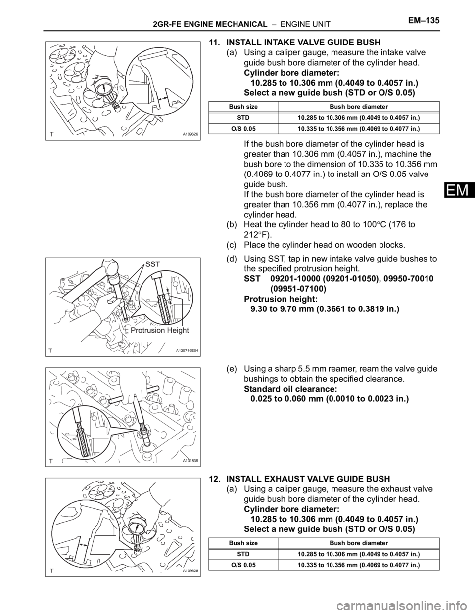
(a) Using a caliper gauge, measure the intake valve
guide bush bore diameter of the cylinder head.
Cylinder bore diameter:
10.285 to 10.306 mm (0.4049 to 0.4057 in.)
Select a new guide bush (STD or O/S 0.05)
If the bush bore diameter of the cylinder head is
greater than 10.306 mm (0.4057 in.), machine the
bush bore to the dimension of 10.335 to 10.356 mm
(0.4069 to 0.4077 in.) to install an O/S 0.05 valve
guide bush.
If the bush bore diameter of the cylinder head is
greater than 10.356 mm (0.4077 in.), replace the
cylinder head.
(b) Heat the cylinder head to 80 to 100
C (176 to
212
F).
(c) Place the cylinder head on wooden blocks.
(d) Using SST, tap in new intake valve guide bushes to
the specified protrusion height.
SST 09201-10000 (09201-01050), 09950-70010
(09951-07100)
Protrusion height:
9.30 to 9.70 mm (0.3661 to 0.3819 in.)
(e) Using a sharp 5.5 mm reamer, ream the valve guide
bushings to obtain the specified clearance.
Standard oil clearance:
0.025 to 0.060 mm (0.0010 to 0.0023 in.)
12. INSTALL EXHAUST VALVE GUIDE BUSH
(a) Using a caliper gauge, measure the exhaust valve
guide bush bore diameter of the cylinder head.
Cylinder bore diameter:
10.285 to 10.306 mm (0.4049 to 0.4057 in.)
Select a new guide bush (STD or O/S 0.05)
A109626
Bush size Bush bore diameter
STD 10.285 to 10.306 mm (0.4049 to 0.4057 in.)
O/S 0.05 10.335 to 10.356 mm (0.4069 to 0.4077 in.)
A120710E04
A131839
A109628
Bush size Bush bore diameter
STD 10.285 to 10.306 mm (0.4049 to 0.4057 in.)
O/S 0.05 10.335 to 10.356 mm (0.4069 to 0.4077 in.)
Page 945 of 3000
EM–1362GR-FE ENGINE MECHANICAL – ENGINE UNIT
EM
If the bush bore diameter of the cylinder head is
greater than 10.306 mm (0.4057 in.), machine the
bush bore to the dimension of 10.335 to 10.356 mm
(0.4069 to 0.4077 in.) to install an O/S 0.05 valve
guide bush.
If the bush bore diameter of the cylinder head is
greater than 10.356 mm (0.4077 in.), replace the
cylinder head.
(b) Heat the cylinder head to 80 to 100
C (176 to
212
F).
(c) Place the cylinder head on wooden blocks.
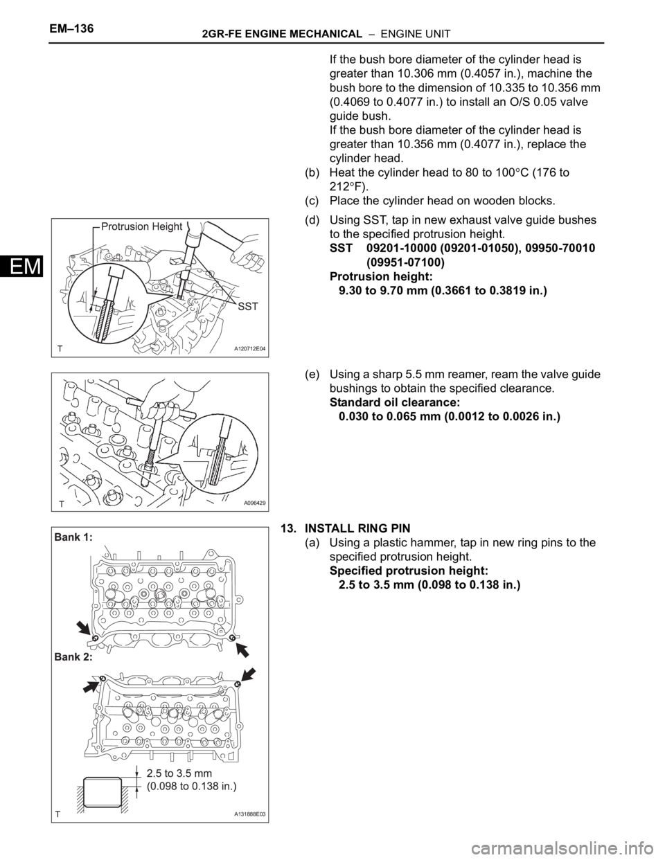
(d) Using SST, tap in new exhaust valve guide bushes
to the specified protrusion height.
SST 09201-10000 (09201-01050), 09950-70010
(09951-07100)
Protrusion height:
9.30 to 9.70 mm (0.3661 to 0.3819 in.)
(e) Using a sharp 5.5 mm reamer, ream the valve guide
bushings to obtain the specified clearance.
Standard oil clearance:
0.030 to 0.065 mm (0.0012 to 0.0026 in.)
13. INSTALL RING PIN
(a) Using a plastic hammer, tap in new ring pins to the
specified protrusion height.
Specified protrusion height:
2.5 to 3.5 mm (0.098 to 0.138 in.)
A120712E04
A096429
A131888E03
Page 948 of 3000
2GR-FE ENGINE MECHANICAL – ENGINE UNITEM–139
EM
17. INSTALL STRAIGHT PIN
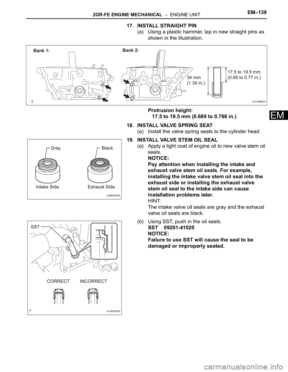
(a) Using a plastic hammer, tap in new straight pins as
shown in the illustration.
Protrusion height:
17.5 to 19.5 mm (0.689 to 0.768 in.)
18. INSTALL VALVE SPRING SEAT
(a) Install the valve spring seats to the cylinder head.
19. INSTALL VALVE STEM OIL SEAL
(a) Apply a light coat of engine oil to new valve stem oil
seals.
NOTICE:
Pay attention when installing the intake and
exhaust valve stem oil seals. For example,
installing the intake valve stem oil seal into the
exhaust side or installing the exhaust valve
stem oil seal to the intake side can cause
installation problems later.
HINT:
The intake valve oil seals are gray and the exhaust
valve oil seals are black.
(b) Using SST, push in the oil seals.
SST 09201-41020
NOTICE:
Failure to use SST will cause the seal to be
damaged or improperly seated.
A131890E03
A094934E04
A124592E02
Page 1048 of 3000
2GR-FE ENGINE MECHANICAL – ENGINE UNITEM–101
EM
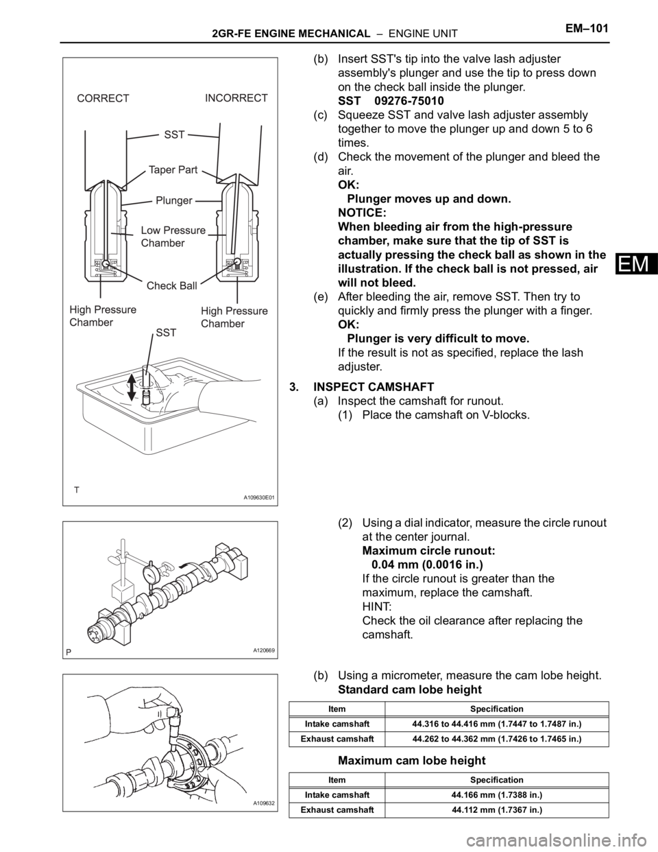
(b) Insert SST's tip into the valve lash adjuster
assembly's plunger and use the tip to press down
on the check ball inside the plunger.
SST 09276-75010
(c) Squeeze SST and valve lash adjuster assembly
together to move the plunger up and down 5 to 6
times.
(d) Check the movement of the plunger and bleed the
air.
OK:
Plunger moves up and down.
NOTICE:
When bleeding air from the high-pressure
chamber, make sure that the tip of SST is
actually pressing the check ball as shown in the
illustration. If the check ball is not pressed, air
will not bleed.
(e) After bleeding the air, remove SST. Then try to
quickly and firmly press the plunger with a finger.
OK:
Plunger is very difficult to move.
If the result is not as specified, replace the lash
adjuster.
3. INSPECT CAMSHAFT
(a) Inspect the camshaft for runout.
(1) Place the camshaft on V-blocks.
(2) Using a dial indicator, measure the circle runout
at the center journal.
Maximum circle runout:
0.04 mm (0.0016 in.)
If the circle runout is greater than the
maximum, replace the camshaft.
HINT:
Check the oil clearance after replacing the
camshaft.
(b) Using a micrometer, measure the cam lobe height.
Standard cam lobe height
Maximum cam lobe height
A109630E01
A120669
A109632
Item Specification
Intake camshaft 44.316 to 44.416 mm (1.7447 to 1.7487 in.)
Exhaust camshaft 44.262 to 44.362 mm (1.7426 to 1.7465 in.)
Item Specification
Intake camshaft 44.166 mm (1.7388 in.)
Exhaust camshaft 44.112 mm (1.7367 in.)
Page 1082 of 3000
2GR-FE ENGINE MECHANICAL – ENGINE UNITEM–135
EM
11. INSTALL INTAKE VALVE GUIDE BUSH
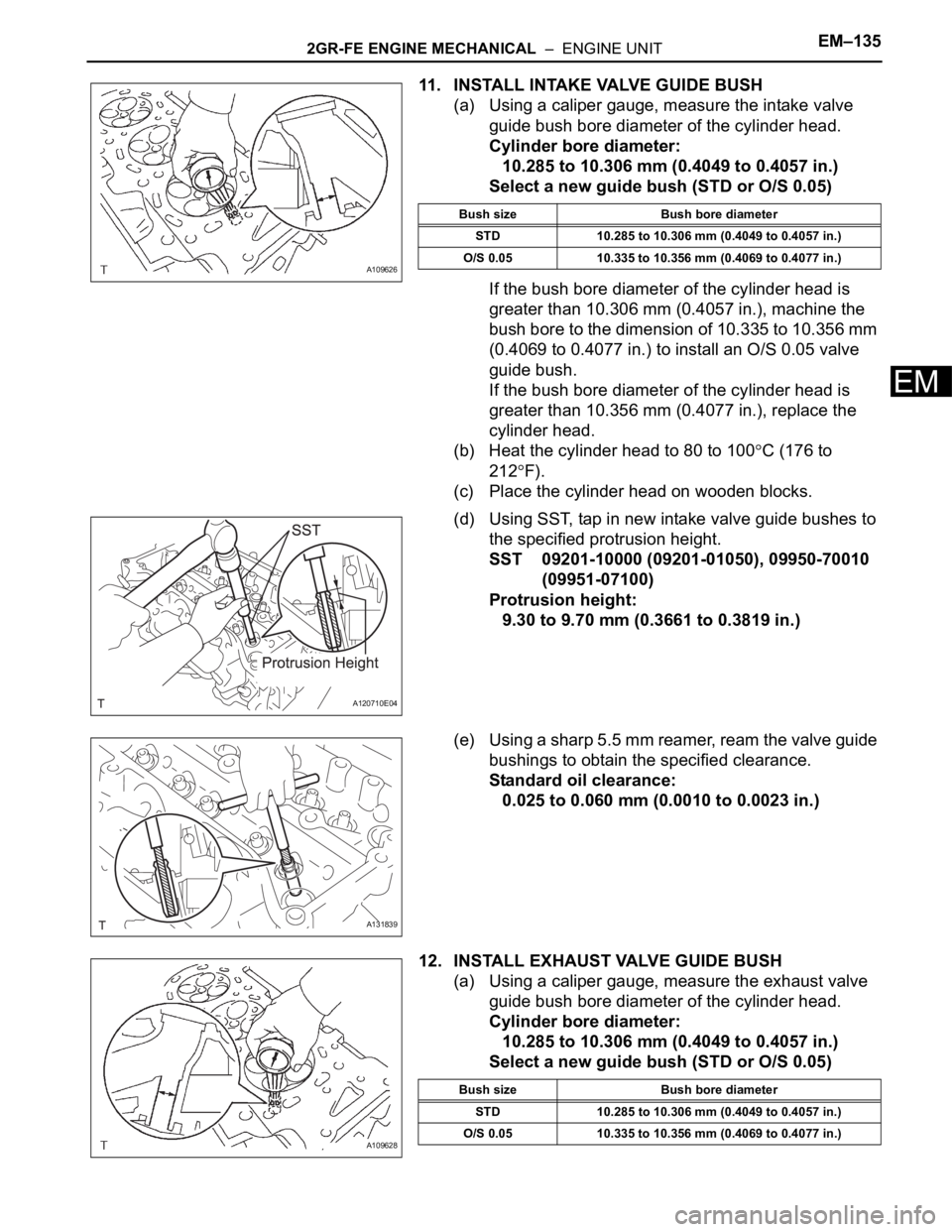
(a) Using a caliper gauge, measure the intake valve
guide bush bore diameter of the cylinder head.
Cylinder bore diameter:
10.285 to 10.306 mm (0.4049 to 0.4057 in.)
Select a new guide bush (STD or O/S 0.05)
If the bush bore diameter of the cylinder head is
greater than 10.306 mm (0.4057 in.), machine the
bush bore to the dimension of 10.335 to 10.356 mm
(0.4069 to 0.4077 in.) to install an O/S 0.05 valve
guide bush.
If the bush bore diameter of the cylinder head is
greater than 10.356 mm (0.4077 in.), replace the
cylinder head.
(b) Heat the cylinder head to 80 to 100
C (176 to
212
F).
(c) Place the cylinder head on wooden blocks.
(d) Using SST, tap in new intake valve guide bushes to
the specified protrusion height.
SST 09201-10000 (09201-01050), 09950-70010
(09951-07100)
Protrusion height:
9.30 to 9.70 mm (0.3661 to 0.3819 in.)
(e) Using a sharp 5.5 mm reamer, ream the valve guide
bushings to obtain the specified clearance.
Standard oil clearance:
0.025 to 0.060 mm (0.0010 to 0.0023 in.)
12. INSTALL EXHAUST VALVE GUIDE BUSH
(a) Using a caliper gauge, measure the exhaust valve
guide bush bore diameter of the cylinder head.
Cylinder bore diameter:
10.285 to 10.306 mm (0.4049 to 0.4057 in.)
Select a new guide bush (STD or O/S 0.05)
A109626
Bush size Bush bore diameter
STD 10.285 to 10.306 mm (0.4049 to 0.4057 in.)
O/S 0.05 10.335 to 10.356 mm (0.4069 to 0.4077 in.)
A120710E04
A131839
A109628
Bush size Bush bore diameter
STD 10.285 to 10.306 mm (0.4049 to 0.4057 in.)
O/S 0.05 10.335 to 10.356 mm (0.4069 to 0.4077 in.)
Page 1083 of 3000

EM–1362GR-FE ENGINE MECHANICAL – ENGINE UNIT
EM
If the bush bore diameter of the cylinder head is
greater than 10.306 mm (0.4057 in.), machine the
bush bore to the dimension of 10.335 to 10.356 mm
(0.4069 to 0.4077 in.) to install an O/S 0.05 valve
guide bush.
If the bush bore diameter of the cylinder head is
greater than 10.356 mm (0.4077 in.), replace the
cylinder head.
(b) Heat the cylinder head to 80 to 100
C (176 to
212
F).
(c) Place the cylinder head on wooden blocks.
(d) Using SST, tap in new exhaust valve guide bushes
to the specified protrusion height.
SST 09201-10000 (09201-01050), 09950-70010
(09951-07100)
Protrusion height:
9.30 to 9.70 mm (0.3661 to 0.3819 in.)
(e) Using a sharp 5.5 mm reamer, ream the valve guide
bushings to obtain the specified clearance.
Standard oil clearance:
0.030 to 0.065 mm (0.0012 to 0.0026 in.)
13. INSTALL RING PIN
(a) Using a plastic hammer, tap in new ring pins to the
specified protrusion height.
Specified protrusion height:
2.5 to 3.5 mm (0.098 to 0.138 in.)
A120712E04
A096429
A131888E03
Page 1086 of 3000
2GR-FE ENGINE MECHANICAL – ENGINE UNITEM–139
EM
17. INSTALL STRAIGHT PIN
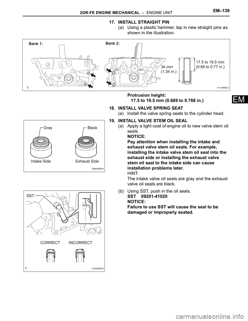
(a) Using a plastic hammer, tap in new straight pins as
shown in the illustration.
Protrusion height:
17.5 to 19.5 mm (0.689 to 0.768 in.)
18. INSTALL VALVE SPRING SEAT
(a) Install the valve spring seats to the cylinder head.
19. INSTALL VALVE STEM OIL SEAL
(a) Apply a light coat of engine oil to new valve stem oil
seals.
NOTICE:
Pay attention when installing the intake and
exhaust valve stem oil seals. For example,
installing the intake valve stem oil seal into the
exhaust side or installing the exhaust valve
stem oil seal to the intake side can cause
installation problems later.
HINT:
The intake valve oil seals are gray and the exhaust
valve oil seals are black.
(b) Using SST, push in the oil seals.
SST 09201-41020
NOTICE:
Failure to use SST will cause the seal to be
damaged or improperly seated.
A131890E03
A094934E04
A124592E02