2007 TOYOTA SIENNA manual transmission
[x] Cancel search: manual transmissionPage 1 of 3000

INTRODUCTION – REPAIR INSTRUCTIONIN–25
IN
VEHICLE LIFT AND SUPPORT
LOCATIONS
1. NOTICE ABOUT VEHICLE CONDITION WHEN
JACKING UP VEHICLE
(a) The vehicle must be unloaded before jacking up/
lifting up the vehicle. Never jack up/lift up a heavily
loaded vehicle.
(b) When removing heavy parts such as the engine and
transmission, the center of gravity of the vehicle
may shift. To stabilize the vehicle, place a balance
weight in a location where it will not roll or shift, or
use a transmission jack to hold the jacking support.
2. NOTICE FOR USING 4 POST LIFT
(a) Follow the safety procedures outlined in the lift
instruction manual.
(b) Use precautionary measures to prevent the free
wheel beam from damaging tires or wheels.
(c) Use wheel chocks to secure the vehicle.
3. NOTICE FOR USING JACK AND SAFETY STAND
(a) Work on a level surface. Use wheel chocks at all
times.
(b) Set the jack and rigid racks to the specified
locations of the vehicle accurately.
(c) When jacking up the vehicle, first release the
parking brake and move the shift lever to N.
(d) When jacking up the entire vehicle:
(1) When jacking up the front wheels first, make
sure wheel chocks are behind the rear wheels.
(2) When jacking up the rear wheels first, make sure
wheel chocks are in front of the front wheels.
(e) When jacking up only the front or rear wheels of the
vehicle:
(1) Before jacking up the front wheels, place wheel
chocks on both sides of the rear wheels.
(2) Before jacking up the rear wheels, place wheel
chocks on both sides of the front wheels.
(f) When lowering a vehicle that only has its front or
rear wheels jacked up:
(1) Before lowering the front wheels, make sure
wheel chocks are in front of the rear wheels.
(2) Before lowering the rear wheels, make sure
wheel chocks are behind the front wheels.
Page 17 of 3000

SERVICE SPECIFICATIONS – U151E AUTOMATIC TRANSAXLESS–31
SS
Transaxle housing x Transaxle case Bolt A 22 225 16
Bolt B 29 300 22
Bolt C 29 295 21
Bolt D 22 226 16
Automatic transmission case plug x Transaxle housing 7.4 75 65 in.*lbf
Automatic transmission case plug x Transaxle case 7.4 75 65 in.*lbf
Parking lock pawl bracket x Transaxle case 20 205 15
Manual detent spring x Transaxle case Bolt A 20 205 15
Bolt B 12 120 9
Transmission wire x Transaxle housing 5.4 55 48 in.*lbf
Transmission valve body x Transaxle case 11 110 8
ATF temperature sensor clamp x Transmission valve body 6.6 67 58 in.*lbf
Valve body oil strainer assembly x Transmission valve body 11 1108
Automatic transaxle oil pan sub-assembly x Transaxle case 7.8 80 69 in.*lbf
Drain plug x Automatic transaxle oil pan sub-assembly 49 500 36
Speed sensor x Transaxle case11 11 5 8
Oil cooler tube union x Transaxle case Union 27 276 20
Elbow 27 276 20
Park/neutral start switch x nut6.9 70 61 in.*lbf
Park/neutral start switch x Bolt5.4 55 48 in.*lbf
Park/neutral start switch x Control shaft lever 13 130 9
Speedometer driven hole cover sub-assembly x Transaxle case 6.9 7061
Oil pump body x Stator shaft assembly 9.8 100 87 in.*lbf
Line pressure control solenoid assembly x Transmission valve body assembly 6.6 67 58 in.*lbf
Shift solenoid valve SL1 x Transmission valve body assembly 6.6 67 58 in.*lbf
Shift solenoid valve SL2 x Transmission valve body assembly 10.811 0 8
Shift solenoid valve SL3 x Transmission valve body assembly 6.6 67 58 in.*lbf
Shift solenoid valve S4 x Transmission valve body assembly 10.8 110 8
Shift solenoid valve DSL x Transmission valve body assembly 10.811 0 8
Front differential case x Front differential ring gear 95.1 970 70Part Tightened N*m kgf*cm ft*lbf
Page 180 of 3000

BC–4BRAKE CONTROL – ANTI-LOCK BRAKE SYSTEM
BC
TEST MODE PROCEDURE
1. SPEED SENSOR SIGNAL CHECK (WHEN USING SST
CHECK WIRE):
HINT:
• If the ignition switch is turned from the ON to the ACC
or LOCK position during Test Mode, the DTCs of the
signal check function will be erased.
(a) Turn the ignition switch off.
(b) Check that the steering wheel is in the straight-
ahead position and move the shift lever to the P
position (Automatic Transmission) or apply the
parking brake (Manual Transmission).
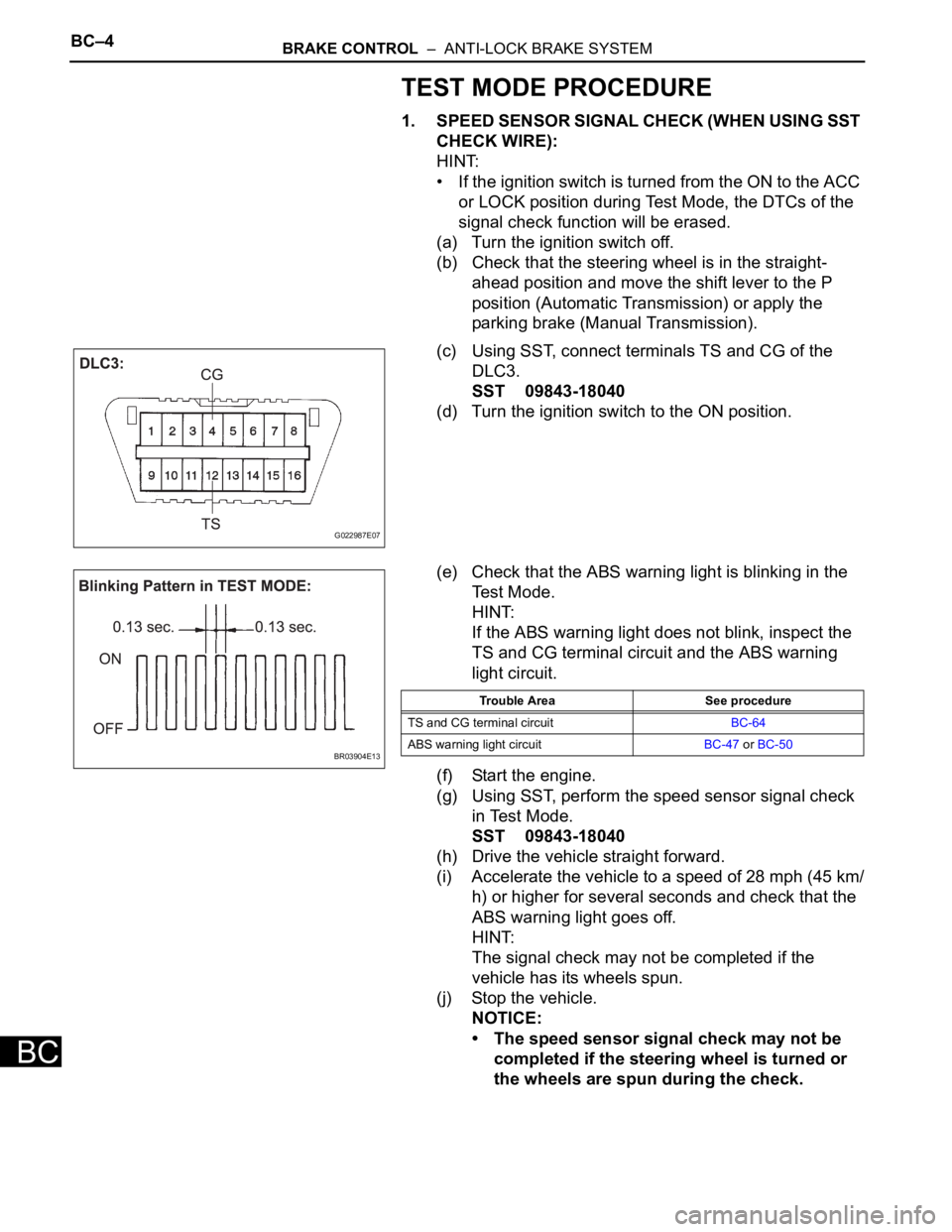
(c) Using SST, connect terminals TS and CG of the
DLC3.
SST 09843-18040
(d) Turn the ignition switch to the ON position.
(e) Check that the ABS warning light is blinking in the
Test Mode.
HINT:
If the ABS warning light does not blink, inspect the
TS and CG terminal circuit and the ABS warning
light circuit.
(f) Start the engine.
(g) Using SST, perform the speed sensor signal check
in Test Mode.
SST 09843-18040
(h) Drive the vehicle straight forward.
(i) Accelerate the vehicle to a speed of 28 mph (45 km/
h) or higher for several seconds and check that the
ABS warning light goes off.
HINT:
The signal check may not be completed if the
vehicle has its wheels spun.
(j) Stop the vehicle.
NOTICE:
• The speed sensor signal check may not be
completed if the steering wheel is turned or
the wheels are spun during the check.
G022987E07
BR03904E13
Trouble Area See procedure
TS and CG terminal circuitBC-64
ABS warning light circuitBC-47 or BC-50
Page 215 of 3000

SS–38SERVICE SPECIFICATIONS – U151F AUTOMATIC TRANSAXLE
SS
Transaxle housing x Transaxle case Bolt A 22 225 16
Bolt B 29 300 22
Bolt C 29 295 21
Bolt D 22 226 16
Automatic transmission case plug x Transaxle housing 7.4 75 65 in.*lbf
Automatic transmission case plug x Transaxle case 7.4 75 65 in.*lbf
Parking lock pawl bracket x Transaxle case 20 205 15
Manual detent spring x Transaxle case Bolt A 20 205 15
Bolt B 12 120 9
Transmission wire x Transaxle housing 5.4 55 48 in.*lbf
Transmission valve body x Transaxle case 11 110 8
ATF temperature sensor clamp x Transmission valve body 6.6 67 58 in.*lbf
Valve body oil strainer assembly x Transmission valve body 11 1108
Automatic transaxle oil pan sub-assembly x Transaxle case 7.8 80 69 in.*lbf
Drain plug x Automatic transaxle oil pan sub-assembly 49 500 36
Speed sensor x Transaxle case11 11 5 8
Oil cooler tube union x Transaxle case Union 27 276 20
Elbow 27 276 20
Park/neutral start switch x nut6.9 70 61 in.*lbf
Park/neutral start switch x Bolt5.4 55 48 in.*lbf
Park/neutral start switch x Control shaft lever 13 130 9
Speedometer driven hole cover sub-assembly x Transaxle case 6.9 7061
Oil pump body x Stator shaft assembly 9.8 100 87 in.*lbf
Line pressure control solenoid assembly x Transmission valve body assembly 6.6 67 58 in.*lbf
Shift solenoid valve SL1 x Transmission valve body assembly 6.6 67 58 in.*lbf
Shift solenoid valve SL2 x Transmission valve body assembly 10.811 0 8
Shift solenoid valve SL3 x Transmission valve body assembly 6.6 67 58 in.*lbf
Shift solenoid valve S4 x Transmission valve body assembly 10.8 110 8
Shift solenoid valve DSL x Transmission valve body assembly 10.811 0 8
Front differential case x Front differential ring gear 95.1 970 70Part Tightened N*m kgf*cm ft*lbf
Page 361 of 3000

2GR-FE ENGINE CONTROL SYSTEM – SFI SYSTEMES–43
ES
5. DLC3 (Data Link Connector 3)
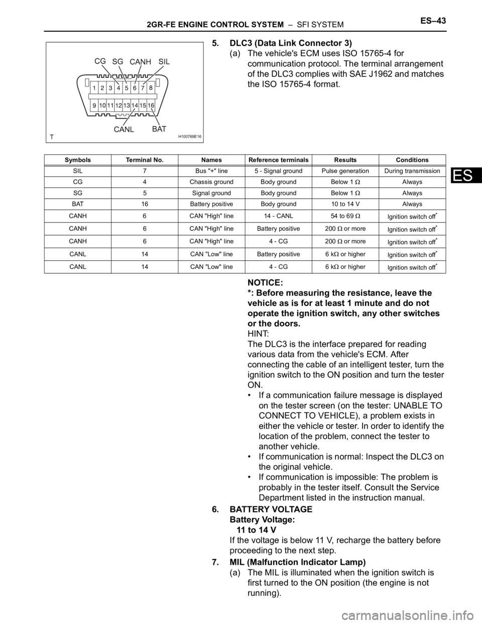
(a) The vehicle's ECM uses ISO 15765-4 for
communication protocol. The terminal arrangement
of the DLC3 complies with SAE J1962 and matches
the ISO 15765-4 format.
NOTICE:
*: Before measuring the resistance, leave the
vehicle as is for at least 1 minute and do not
operate the ignition switch, any other switches
or the doors.
HINT:
The DLC3 is the interface prepared for reading
various data from the vehicle's ECM. After
connecting the cable of an intelligent tester, turn the
ignition switch to the ON position and turn the tester
ON.
• If a communication failure message is displayed
on the tester screen (on the tester: UNABLE TO
CONNECT TO VEHICLE), a problem exists in
either the vehicle or tester. In order to identify the
location of the problem, connect the tester to
another vehicle.
• If communication is normal: Inspect the DLC3 on
the original vehicle.
• If communication is impossible: The problem is
probably in the tester itself. Consult the Service
Department listed in the instruction manual.
6. BATTERY VOLTAGE
Battery Voltage:
11 to 14 V
If the voltage is below 11 V, recharge the battery before
proceeding to the next step.
7. MIL (Malfunction Indicator Lamp)
(a) The MIL is illuminated when the ignition switch is
first turned to the ON position (the engine is not
running).
H100769E16
Symbols Terminal No. Names Reference terminals Results Conditions
SIL 7 Bus "+" line 5 - Signal ground Pulse generation During transmission
CG 4 Chassis ground Body ground Below 1
Always
SG 5 Signal ground Body ground Below 1
Always
BAT 16 Battery positive Body ground 10 to 14 V Always
CANH 6 CAN "High" line 14 - CANL 54 to 69
Ignition switch off*
CANH 6 CAN "High" line Battery positive 200 or more
Ignition switch off*
CANH 6 CAN "High" line 4 - CG 200 or more
Ignition switch off*
CANL 14 CAN "Low" line Battery positive 6 k or higher
Ignition switch off*
CANL 14 CAN "Low" line 4 - CG 6 k or higher
Ignition switch off*
Page 825 of 3000

2GR-FE ENGINE CONTROL SYSTEM – SFI SYSTEMES–43
ES
5. DLC3 (Data Link Connector 3)
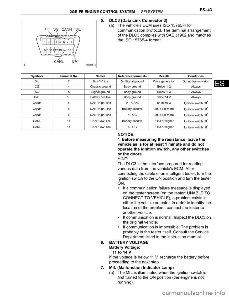
(a) The vehicle's ECM uses ISO 15765-4 for
communication protocol. The terminal arrangement
of the DLC3 complies with SAE J1962 and matches
the ISO 15765-4 format.
NOTICE:
*: Before measuring the resistance, leave the
vehicle as is for at least 1 minute and do not
operate the ignition switch, any other switches
or the doors.
HINT:
The DLC3 is the interface prepared for reading
various data from the vehicle's ECM. After
connecting the cable of an intelligent tester, turn the
ignition switch to the ON position and turn the tester
ON.
• If a communication failure message is displayed
on the tester screen (on the tester: UNABLE TO
CONNECT TO VEHICLE), a problem exists in
either the vehicle or tester. In order to identify the
location of the problem, connect the tester to
another vehicle.
• If communication is normal: Inspect the DLC3 on
the original vehicle.
• If communication is impossible: The problem is
probably in the tester itself. Consult the Service
Department listed in the instruction manual.
6. BATTERY VOLTAGE
Battery Voltage:
11 to 14 V
If the voltage is below 11 V, recharge the battery before
proceeding to the next step.
7. MIL (Malfunction Indicator Lamp)
(a) The MIL is illuminated when the ignition switch is
first turned to the ON position (the engine is not
running).
H100769E16
Symbols Terminal No. Names Reference terminals Results Conditions
SIL 7 Bus "+" line 5 - Signal ground Pulse generation During transmission
CG 4 Chassis ground Body ground Below 1
Always
SG 5 Signal ground Body ground Below 1
Always
BAT 16 Battery positive Body ground 10 to 14 V Always
CANH 6 CAN "High" line 14 - CANL 54 to 69
Ignition switch off*
CANH 6 CAN "High" line Battery positive 200 or more
Ignition switch off*
CANH 6 CAN "High" line 4 - CG 200 or more
Ignition switch off*
CANL 14 CAN "Low" line Battery positive 6 k or higher
Ignition switch off*
CANL 14 CAN "Low" line 4 - CG 6 k or higher
Ignition switch off*
Page 1394 of 3000

U151E AUTOMATIC TRANSAXLE – AUTOMATIC TRANSAXLE SYSTEMAX–17
AX
MANUAL SHIFTING TEST
1. PERFORM MANUAL SHIFTING TEST
HINT:
• With this test, it can be determined whether the
trouble occurs in the electrical circuit or is a
mechanical problem in the transaxle.
• If any abnormalities are found in the following test, the
problem is in the transaxle itself.
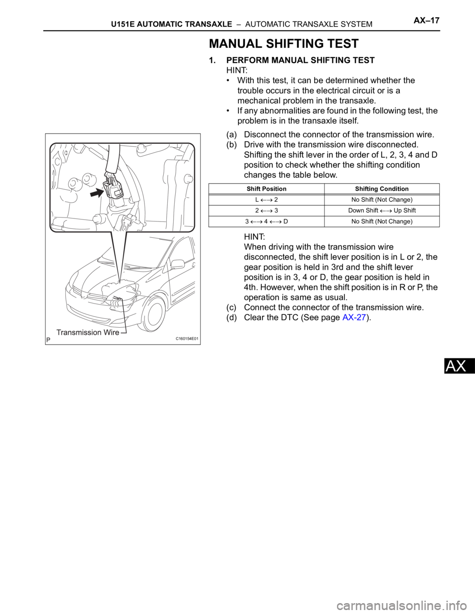
(a) Disconnect the connector of the transmission wire.
(b) Drive with the transmission wire disconnected.
Shifting the shift lever in the order of L, 2, 3, 4 and D
position to check whether the shifting condition
changes the table below.
HINT:
When driving with the transmission wire
disconnected, the shift lever position is in L or 2, the
gear position is held in 3rd and the shift lever
position is in 3, 4 or D, the gear position is held in
4th. However, when the shift position is in R or P, the
operation is same as usual.
(c) Connect the connector of the transmission wire.
(d) Clear the DTC (See page AX-27).
C160154E01
Shift Position Shifting Condition
L
2 No Shift (Not Change)
2
3 Down Shift Up Shift
3
4 D No Shift (Not Change)
Page 1406 of 3000

AX–36U151E AUTOMATIC TRANSAXLE – AUTOMATIC TRANSAXLE SYSTEM
AX
FAIL-SAFE CHART
1. FAIL-SAFE
This function minimizes the loss of the ECT functions
when any malfunction occurs in a sensor or solenoid.
(a) ATF (Automatic Transmission Fluid) temperature
sensor:
When the ATF temperature sensor has a
malfunction, 5th upshift is prohibited.
(b) Counter gear speed sensor NC (Speed sensor NC):
When the counter gear speed sensor has a
malfunction, 5th upshift is prohibited.
(c) Shift solenoid valve DSL:
When the solenoid valve DSL has a malfunction, the
current to the solenoid valve is stopped.
This stops lock-up control, then fuel economy
decreases.
(d) Shift solenoid valve SL1, SL2, SL3 and S4:
Fail safe function:
If either of the shift solenoid valve circuits develops
an open or short, the ECM turns the other shift
solenoid "ON" and "OFF" in order to shift into the
gear positions shown in the table below.
Manual shifting as shown in the following table must
be done (In case of a short circuit, the ECM stops
sending the current to the short circuited solenoid).
Even if starting the engine in the fail-safe mode, the
gear position remains in the same position.
HINT:
FL: Flex Lock-up
NormalSolenoid ValveSL1 ON OFF ON OFF OFF
SL2 ON ON OFF FL FL
SL3 OFF OFF OFF ON ON
S4 OFF OFF OFF OFF ON
Gear Position 1st 2nd 3rd 4th 5th
SL1
Malfunction
(During driving
at 1st or 2nd)Solenoid ValveSL1 OFF
SL2 ON ON OFF to ON FL to ON FL to ON
SL3 OFF OFF OFF ON to OFF ON to OFF
S4 OFF OFF OFF OFF ON to OFF
Gear Position 1st to 2nd 2nd 3rd to 2nd 4th to 2nd 5th to 2nd
SL1
Malfunction
(During driving
at 3rd)Solenoid ValveSL1 OFF
SL2 ON to FL ON to FL OFF to FL FL FL
SL3 OFF OFF OFF ON to OFF ON to OFF
S4 OFF to ON OFF to ON OFF to ON OFF to ON ON
Gear Position 1st to 4th 2nd to 4th 3rd to 4th 4th 5th to 4th
SL1
Malfunction
(During driving
at 4th or 5th)Solenoid ValveSL1 OFF
SL2 ON to FL ON to FL OFF to FL FL FL
SL3 OFF to ON OFF to ON OFF to ON ON ON
S4 OFF OFF OFF OFF ON
Gear Position 1st to 4th 2nd to 4th 3rd to 4th 4th 5th to 4th