AC–14AIR CONDITIONING – AIR CONDITIONING SYSTEM (for Automatic Air Conditioning Sys-
tem)
AC
(b) Waveform 2:
(c) Waveform 3:
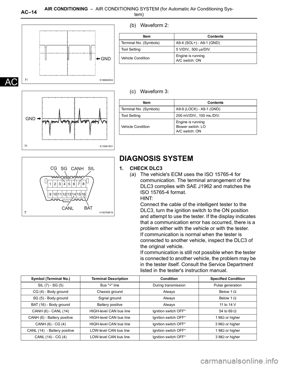
DIAGNOSIS SYSTEM
1. CHECK DLC3
(a) The vehicle's ECM uses the ISO 15765-4 for
communication. The terminal arrangement of the
DLC3 complies with SAE J1962 and matches the
ISO 15765-4 format.
HINT:
Connect the cable of the intelligent tester to the
DLC3, turn the ignition switch to the ON position
and attempt to use the tester. If the display indicates
that a communication error has occurred, there is a
problem either with the vehicle or with the tester.
If communication is normal when the tester is
connected to another vehicle, inspect the DLC3 of
the original vehicle.
If communication is still not possible when the tester
is connected to another vehicle, the problem may be
in the tester itself. Consult the Service Department
listed in the tester's instruction manual.
E106664E02
Item Contents
Terminal No. (Symbols) A9-4 (SOL+) - A9-1 (GND)
Tool Setting 5 V/DIV., 500
s/DIV.
Vehicle ConditionEngine is running
A/C switch: ON
E116941E01
Item Contents
Terminal No. (Symbols) A9-9 (LOCK) - A9-1 (GND)
Tool Setting 200 mV/DIV., 100 ms./DIV.
Vehicle ConditionEngine is running
Blower switch: LO
A/C switch: ON
H100769E16
Symbol (Terminal No.) Terminal Description Condition Specified Condition
SIL (7) - SG (5) Bus "+" line During transmission Pulse generation
CG (4) - Body ground Chassis ground Always Below 1
SG (5) - Body ground Signal ground Always Below 1
BAT (16) - Body ground Battery positive Always 11 to 14 V
CANH (6) - CANL (14) HIGH-level CAN bus line Ignition switch OFF*54 to 69
CANH (6) - Battery positive HIGH-level CAN bus line Ignition switch OFF* 1 M or higher
CANH (6) - CG (4) HIGH-level CAN bus line Ignition switch OFF* 3 M
or higher
CANL (14) - Battery positive LOW-level CAN bus line Ignition switch OFF* 1 M
or higher
CANL (14) - CG (4) LOW-level CAN bus line Ignition switch OFF* 3 M
or higher