Page 7 of 3000
PP–6PREPARATION – 2GR-FE ENGINE MECHANICAL
PP
EQUIPMENT
Abrasive compound
Brush
Caliper gauge
Carbide cutter (30
)
Carbide cutter (45
)
Carbide cutter (60
)
Carbide cutter (75
)
Connecting rod aligner
Cylinder gauge
Dial indicator
Dye penetrant
Engine tune-up tester
Groove cleaning tool
Heater
Micrometer
Piston ring compressor
Piston ring expander
Plastigage
Precision straight edge
Press
Reamer (5.5 mm)
Ridge reamer
Soft brush
Solvent
Spring tester
Steel square
Thermometer
To r q u e w r e n c h
Torx socket wrench
Valve seat cutter
Valve guide bushing brush
V-block
Vernier calipers
Wire brush
Bar
Chain Block
CO/HC meter
Compression gauge
Dial indicator with magnetic base
Engine Sling Device
Feeler gauge
Radiator cap tester
Slide calipers
Tachometer
Timing light
Wooden block
Deep socket wrench
Screwdriver
Hammer
Page 40 of 3000
2GR-FE ENGINE MECHANICAL – ENGINE ASSEMBLYEM–41
EM
92. REMOVE ENGINE MOUNTING BRACKET RR (for
4WD)
(a) Remove the 3 bolts and engine mounting bracket
RR.
93. REMOVE GENERATOR ASSEMBLY (See page CH-17)
94. REMOVE COOLER COMPRESSOR ASSEMBLY
95. REMOVE V-RIBBED BELT TENSIONER ASSEMBLY
(a) Remove the 5 bolts and V-ribbed belt tensioner
assembly.
96. REMOVE NO. 2 TIMING GEAR COVER
(a) Remove the 2 bolts and No. 2 timing gear cover.
97. REMOVE NO. 2 IDLER PULLEY SUB-ASSEMBLY
(a) Remove the bolt, plate and No. 2 idler pulley sub-
assembly.
98. REMOVE WATER PUMP PULLEY (See page CO-12)
A143881
A129644
A132987
A129645E01
Page 156 of 3000
PREPARATION – AIR CONDITIONINGPP–65
PP
LUBRICANT
Item Capacity Classification
Compressor oil - ND-OIL 8 or equivalent
Page 197 of 3000

SS–10SERVICE SPECIFICATIONS – 2GR-FE ENGINE MECHANICAL
SS
TORQUE SPECIFICATIONS
Part Tightened N*m kgf*cm ft.*lbf
Ignition coil assembly x Cylinder head cover sub-assembly 10 102 7
No. 1 engine hanger x Cylinder head sub-assembly RH 33 337 24
No. 2 engine hanger x Cylinder head sub-assembly LH 33 337 24
Engine mounting bracket RH x Cylinder block sub-assembly 54 551 40
No. 1 oil level gauge guide x Cylinder head sub-assembly 21 214 15
No. 2 oil level gauge guide x Cylinder block sub-assembly 21 214 15
No. 2 idler pulley sub-assembly x Timing chain cover sub-assembly 43 438 32
V-ribbed belt tensioner assembly x Cylinder block sub-assembly 43 438 32
Intake manifold x Cylinder head sub-assembly 21 214 15
Exhaust manifold sub-assembly RH x Cylinder head sub-assembly
RH21 214 15
Exhaust manifold sub-assembly LH x Cylinder head sub-assembly LH 21 214 15
Drive plate & ring gear sub-assembly x Crankshaft 83 850 61
Air cleaner case sub-assembly x Body 5.0 51 44 in.*lbf
Air cleaner case sub-assembly x Air cleaner bracket 5.0 51 44 in.*lbf
Engine coolant temperature x water by-pass joint RR 20 200 14
Engine assembly with Transaxle x Body A 85 867 63
B 32 329 24
No. 2 manifold stay x Exhaust manifold sub-assembly LH 34 347 25
No. 2 manifold stay x Cylinder block sub-assembly 34 347 25
No. 1 air cleaner inlet x Body 5.0 51 44 in.*lbf
No. 2 air cleaner inlet x Body 5.0 51 44 in.*lbf
Battery clamp x Body Bolt 5.5 56 49 in.*lbf
Nut 5.5 56 49 in.*lbf
Throttle body bracket x Intake air surge tank assembly 21 214 15
Throttle body bracket x Cylinder head cover sub-assembly RH 21 21415
No. 1 surge tank stay x Intake air surge tank assembly 21 214 15
No. 1 surge tank stay x Cylinder head cover sub-assembly RH 21 21415
No. 1 cowl top to cowl brace inner x Body 7.5 76 66 in.*lbf
No. 1 cowl top to cowl brace inner x Front outer cowl top panel sub-
assembly7.5 76 66 in.*lbf
Front outer cowl top panel sub-assembly x Body 7.5 76 66 in.*lbf
Fuel pump resistor x Front outer cowl top panel sub-assembly 7.576 66 in.*lbf
Radio setting condenser x Cylinder head cover sub-assembly RH 10102 7
Radio setting condense x Cylinder head cover sub-assembly LH 10 102 7
Intake air resonator sub-assembly x Body 5.0 51 44 in.*lbf
Air cleaner bracket x Body 7.8 80 69 in.*lbf
No. 1 vacuum switching valve assembly x Cylinder head cover sub-
assembly10 102 7
Engine mounting bracket RR x Cylinder block sub-assembly 64 650 47
Steering intermediate shaft x Steering gear 35 360 26
Stabilizer link x Shock absorber 74 755 55
Tie rod assembly x Steering gear 49 500 36
Front speed sensor x Front axle 8.0 85 71 in.*lbf
Front axle hub nut x Front drive shaft 294 2998 217
Cooler compressor assembly x V-ribbed belt tensioner 25 250 18
Cooler compressor assembly x Discharge hose sub-assembly 5.4 55 48 in.*lbf
Cooler compressor assembly x Suction hose sub-assembly 5.4 55 48 in.*lbf
Page 204 of 3000

AIR CONDITIONING – COMPRESSOR AND MAGNETIC CLUTCHAC–227
AC
REMOVAL
1. RECOVER REFRIGERANT FROM REFRIGERATION
SYSTEM (See page AC-172)
2. REMOVE FRONT WHEEL RH
3. REMOVE FRONT FENDER APRON SEAL RH (See
page EM-26)
4. REMOVE V-RIBBED BELT (See page EM-6)
5. REMOVE RADIATOR AND FAN ASSEMBLY
(See page CO-28)
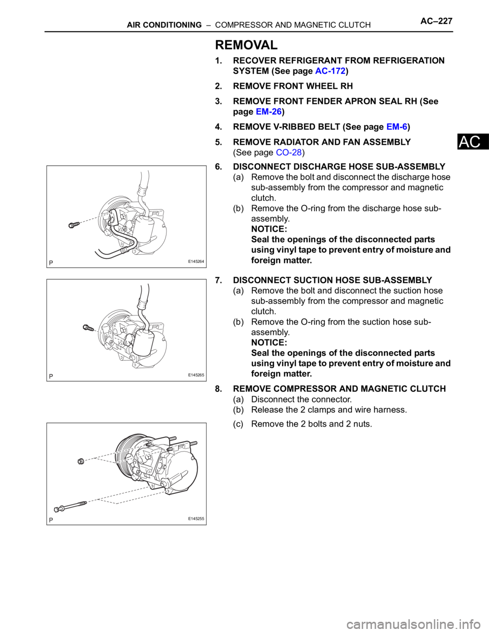
6. DISCONNECT DISCHARGE HOSE SUB-ASSEMBLY
(a) Remove the bolt and disconnect the discharge hose
sub-assembly from the compressor and magnetic
clutch.
(b) Remove the O-ring from the discharge hose sub-
assembly.
NOTICE:
Seal the openings of the disconnected parts
using vinyl tape to prevent entry of moisture and
foreign matter.
7. DISCONNECT SUCTION HOSE SUB-ASSEMBLY
(a) Remove the bolt and disconnect the suction hose
sub-assembly from the compressor and magnetic
clutch.
(b) Remove the O-ring from the suction hose sub-
assembly.
NOTICE:
Seal the openings of the disconnected parts
using vinyl tape to prevent entry of moisture and
foreign matter.
8. REMOVE COMPRESSOR AND MAGNETIC CLUTCH
(a) Disconnect the connector.
(b) Release the 2 clamps and wire harness.
(c) Remove the 2 bolts and 2 nuts.
E145264
E145265
E145255
Page 205 of 3000
AC–228AIR CONDITIONING – COMPRESSOR AND MAGNETIC CLUTCH
AC
(d) Using a "TORX" socket wrench (E8), remove the 2
stud bolts and the compressor and magnetic clutch.
E145254
Page 209 of 3000
AIR CONDITIONING – CONDENSERAC–239
AC
REASSEMBLY
1. INSTALL COOLER DRYER
(a) Using needle nose pliers, install the cooler dryer.
(b) Install a new O-ring on the cap.
(c) Sufficiently apply compressor oil to the fitting
surfaces of the O-ring and the cap.
Compressor oil:
ND-OIL 8 or equivalent
(d) Using a hexagon wrench 14 mm (0.55 in.), install
the cap to the cooler condenser assembly.
Torque: 2.9 N*m (30 kgf*cm, 25 in.*lbf)
INSTALLATION
1. INSTALL COOLER CONDENSER CORE
(a) Install the cooler condenser core with the 2 screws.
Torque: 3.9 N*m (40 kgf*cm, 35 in.*lbf)
HINT:
If the condenser is replaced with a new one, add
compressor oil to the new condenser.
Capacity:
40 cc (1.4 fl.oz.)
Compressor oil:
ND-OIL 8 or equivalent
2. INSTALL NO. 1 RADIATOR SUPPORT (See page CO-
40)
3. INSTALL RADIATOR SUPPORT CUSHION (See page
CO-41)
I032994
E055408
I032993E06
E145272
Page 210 of 3000

AC–240AIR CONDITIONING – CONDENSER
AC
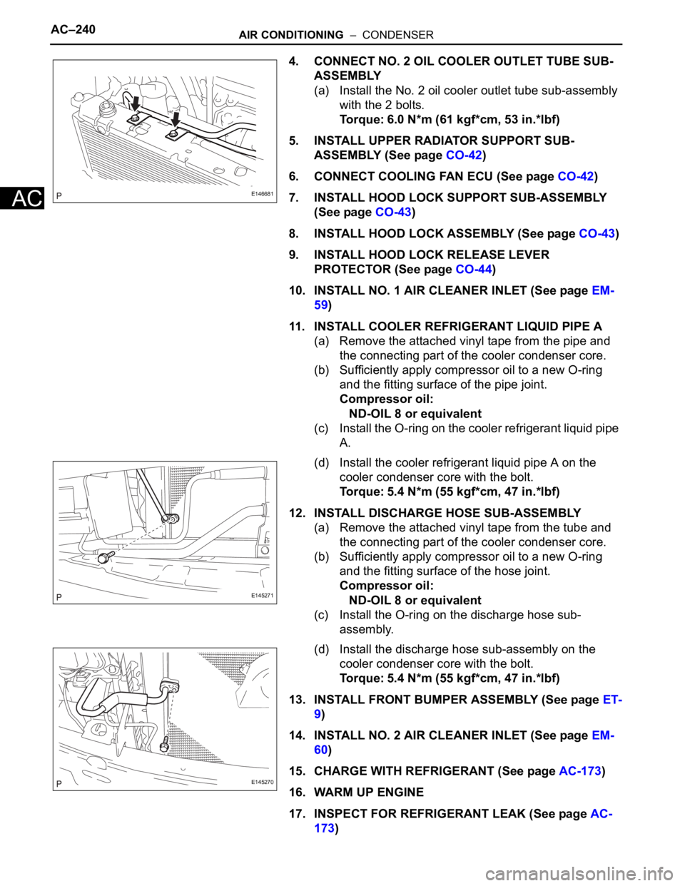
4. CONNECT NO. 2 OIL COOLER OUTLET TUBE SUB-
ASSEMBLY
(a) Install the No. 2 oil cooler outlet tube sub-assembly
with the 2 bolts.
Torque: 6.0 N*m (61 kgf*cm, 53 in.*lbf)
5. INSTALL UPPER RADIATOR SUPPORT SUB-
ASSEMBLY (See page CO-42)
6. CONNECT COOLING FAN ECU (See page CO-42)
7. INSTALL HOOD LOCK SUPPORT SUB-ASSEMBLY
(See page CO-43)
8. INSTALL HOOD LOCK ASSEMBLY (See page CO-43)
9. INSTALL HOOD LOCK RELEASE LEVER
PROTECTOR (See page CO-44)
10. INSTALL NO. 1 AIR CLEANER INLET (See page EM-
59)
11. INSTALL COOLER REFRIGERANT LIQUID PIPE A
(a) Remove the attached vinyl tape from the pipe and
the connecting part of the cooler condenser core.
(b) Sufficiently apply compressor oil to a new O-ring
and the fitting surface of the pipe joint.
Compressor oil:
ND-OIL 8 or equivalent
(c) Install the O-ring on the cooler refrigerant liquid pipe
A.
(d) Install the cooler refrigerant liquid pipe A on the
cooler condenser core with the bolt.
Torque: 5.4 N*m (55 kgf*cm, 47 in.*lbf)
12. INSTALL DISCHARGE HOSE SUB-ASSEMBLY
(a) Remove the attached vinyl tape from the tube and
the connecting part of the cooler condenser core.
(b) Sufficiently apply compressor oil to a new O-ring
and the fitting surface of the hose joint.
Compressor oil:
ND-OIL 8 or equivalent
(c) Install the O-ring on the discharge hose sub-
assembly.
(d) Install the discharge hose sub-assembly on the
cooler condenser core with the bolt.
Torque: 5.4 N*m (55 kgf*cm, 47 in.*lbf)
13. INSTALL FRONT BUMPER ASSEMBLY (See page ET-
9)
14. INSTALL NO. 2 AIR CLEANER INLET (See page EM-
60)
15. CHARGE WITH REFRIGERANT (See page AC-173)
16. WARM UP ENGINE
17. INSPECT FOR REFRIGERANT LEAK (See page AC-
173)
E146681
E145271
E145270