Page 32 of 3000
2GR-FE ENGINE MECHANICAL – ENGINE ASSEMBLYEM–33
EM
(b) Remove the bolt and 2 clamps from the body.
(c) Remove the 2 bolts and 2 ground cables.
(d) Disconnect the engine wire from the ECM and
passenger side junction block.
41. DISCONNECT UNION TO CHECK VALVE HOSE
(a) Using pliers, grip the claws of the clip and slide the
clip to disconnect the union to check valve hose.
42. REMOVE CENTER EXHAUST PIPE ASSEMBLY (for
4WD)
(a) Remove the center exhaust pipe assembly (See
page EX-8).
43. REMOVE FRONT EXHAUST PIPE ASSEMBLY (for
4WD)
(a) Remove the front exhaust pipe assembly (See page
EX-9).
44. REMOVE FRONT EXHAUST PIPE ASSEMBLY (for
2WD)
(a) Remove the front exhaust pipe assembly (See page
EX-3).
A155030
A163267
A162374
Page 34 of 3000
2GR-FE ENGINE MECHANICAL – ENGINE ASSEMBLYEM–35
EM
(b) Remove the 6 bolts, 2 nuts, and frame side rail
plates RH and LH.
(c) Remove the 6 bolts, 2 nuts, and front suspension
member brace rear RH and LH.
(d) Operate the engine lifter, then remove the engine
assembly from the vehicle.
NOTICE:
Make sure that the engine is clear of all wiring
and hoses.
62. REMOVE V-RIBBED BELT (See page EM-6)
63. REMOVE VANE PUMP ASSEMBLY
(a) Disconnect the power steering oil pressure switch
connector.
(b) Remove the 2 nuts.
(c) Loosen the bolt A.
(d) Remove the bolt B.
(e) Remove the bolt A and vane pump assembly.
64. REMOVE FRONT STABILIZER BAR (for 4WD)
HINT:
See page SP-35.
65. REMOVE POWER STEERING LINK
(a) Remove the 2 bolts and power steering link with
vane pump.
A162364
A162363
A155024
A139216E01
Page 36 of 3000
2GR-FE ENGINE MECHANICAL – ENGINE ASSEMBLYEM–37
EM
(c) Remove the bolt and disconnect the engine
mounting insulator FR.
(d) Remove the 2 bolts and separate the engine
mounting insulator RR (for 4WD).
68. REMOVE FRONT DRIVE SHAFT ASSEMBLY LH (See
page DS-6)
69. REMOVE FRONT DRIVE SHAFT ASSEMBLY RH (for
2WD) (See page DS-6)
70. REMOVE FRONT DRIVE SHAFT ASSEMBLY RH (for
4WD) (See page DS-7)
71. REMOVE ENGINE WIRE
72. REMOVE STARTER ASSEMBLY (See page ST-5)
73. REMOVE ENGINE FRONT MOUNTING BRACKET
(See page AX-165)
74. REMOVE MANIFOLD STAY
(a) Remove the bolt, nut, and manifold stay.
75. REMOVE TRANSFER STIFFENER PLATE RH (See
page AX-166)
76. REMOVE AUTOMATIC TRANSAXLE ASSEMBLY (for
2WD)
HINT:
See page AX-165.
77. REMOVE AUTOMATIC TRANSAXLE ASSEMBLY (for
4WD)
AX-166
78. REMOVE DRIVE PLATE AND RING GEAR SUB-
ASSEMBLY (See page EM-12)
79. SECURE ENGINE
(a) Secure the engine onto an engine stand with the
bolts.
A155019
A155018
A155023
Page 40 of 3000
2GR-FE ENGINE MECHANICAL – ENGINE ASSEMBLYEM–41
EM
92. REMOVE ENGINE MOUNTING BRACKET RR (for
4WD)
(a) Remove the 3 bolts and engine mounting bracket
RR.
93. REMOVE GENERATOR ASSEMBLY (See page CH-17)
94. REMOVE COOLER COMPRESSOR ASSEMBLY
95. REMOVE V-RIBBED BELT TENSIONER ASSEMBLY
(a) Remove the 5 bolts and V-ribbed belt tensioner
assembly.
96. REMOVE NO. 2 TIMING GEAR COVER
(a) Remove the 2 bolts and No. 2 timing gear cover.
97. REMOVE NO. 2 IDLER PULLEY SUB-ASSEMBLY
(a) Remove the bolt, plate and No. 2 idler pulley sub-
assembly.
98. REMOVE WATER PUMP PULLEY (See page CO-12)
A143881
A129644
A132987
A129645E01
Page 110 of 3000

DRIVE SHAFT – FRONT DRIVE SHAFTDS–5
DS
REMOVAL
1. DRAIN AUTOMATIC TRANSAXLE FLUID
(a) Remove the drain plug, gasket and drain ATF.
(b) Install a new gasket and the drain plug.
Torque: 49 N*m (500 kgf*cm, 36 ft.*lbf)
2. DRAIN TRANSFER OIL (for 4WD)
HINT:
(See page TF-8)
3. REMOVE FRONT WHEEL
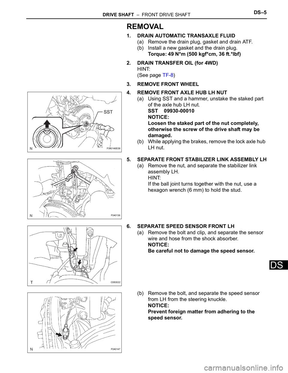
4. REMOVE FRONT AXLE HUB LH NUT
(a) Using SST and a hammer, unstake the staked part
of the axle hub LH nut.
SST 09930-00010
NOTICE:
Loosen the staked part of the nut completely,
otherwise the screw of the drive shaft may be
damaged.
(b) While applying the brakes, remove the lock axle hub
LH nut.
5. SEPARATE FRONT STABILIZER LINK ASSEMBLY LH
(a) Remove the nut, and separate the stabilizer link
assembly LH.
HINT:
If the ball joint turns together with the nut, use a
hexagon wrench (6 mm) to hold the stud.
6. SEPARATE SPEED SENSOR FRONT LH
(a) Remove the bolt and clip, and separate the sensor
wire and hose from the shock absorber.
NOTICE:
Be careful not to damage the speed sensor.
(b) Remove the bolt, and separate the speed sensor
from LH from the steering knuckle.
NOTICE:
Prevent foreign matter from adhering to the
speed sensor.
F040146E09
F040136
C083022
F040147
Page 112 of 3000

DRIVE SHAFT – FRONT DRIVE SHAFTDS–7
DS
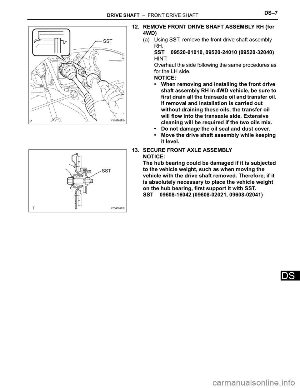
12. REMOVE FRONT DRIVE SHAFT ASSEMBLY RH (for
4WD)
(a) Using SST, remove the front drive shaft assembly
RH.
SST 09520-01010, 09520-24010 (09520-32040)
HINT:
Overhaul the side following the same procedures as
for the LH side.
NOTICE:
• When removing and installing the front drive
shaft assembly RH in 4WD vehicle, be sure to
first drain all the transaxle oil and transfer oil.
If removal and installation is carried out
without draining these oils, the transfer oil
will flow into the transaxle side. Extensive
cleaning will be required if the two oils mix.
• Do not damage the oil seal and dust cover.
• Move the drive shaft assembly while keeping
it level.
13. SECURE FRONT AXLE ASSEMBLY
NOTICE:
The hub bearing could be damaged if it is subjected
to the vehicle weight, such as when moving the
vehicle with the drive shaft removed. Therefore, if it
is absolutely necessary to place the vehicle weight
on the hub bearing, first support it with SST.
SST 09608-16042 (09608-02021, 09608-02041)
C108268E04
C054583E01
Page 115 of 3000
DS–10DRIVE SHAFT – FRONT DRIVE SHAFT
DS
12. REMOVE FRONT DRIVE SHAFT DUST COVER LH
(a) Using SST and a press, remove the drive shaft dust
cover LH.
SST 09950-00020
NOTICE:
Be careful not to drop the inboard joint
assembly.
13. REMOVE FRONT DRIVE SHAFT DUST COVER RH
(for 2WD)
(a) Using a press, remove the drive shaft dust cover
RH.
14. REMOVE FRONT DRIVE SHAFT DUST COVER RH
(for 4WD)
(a) Using SST and a press, remove the drive shaft dust
cover RH.
SST 09950-00020
NOTICE:
Be careful not to drop the inboard joint
assembly.
15. REMOVE FRONT DRIVE SHAFT DUST COVER
(a) Using SST and a press, remove the drive shaft dust
cover.
SST 09950-00020
NOTICE:
Be careful not to drop the inboard joint
assembly.
16. REMOVE FRONT DRIVE SHAFT RH HOLE SNAP
RING
(a) Using a snap ring expander, remove the drive shaft
RH hole snap ring.
F040647E06
C067101
F040648E03
F040208E05
C109617
Page 116 of 3000

DRIVE SHAFT – FRONT DRIVE SHAFTDS–11
DS
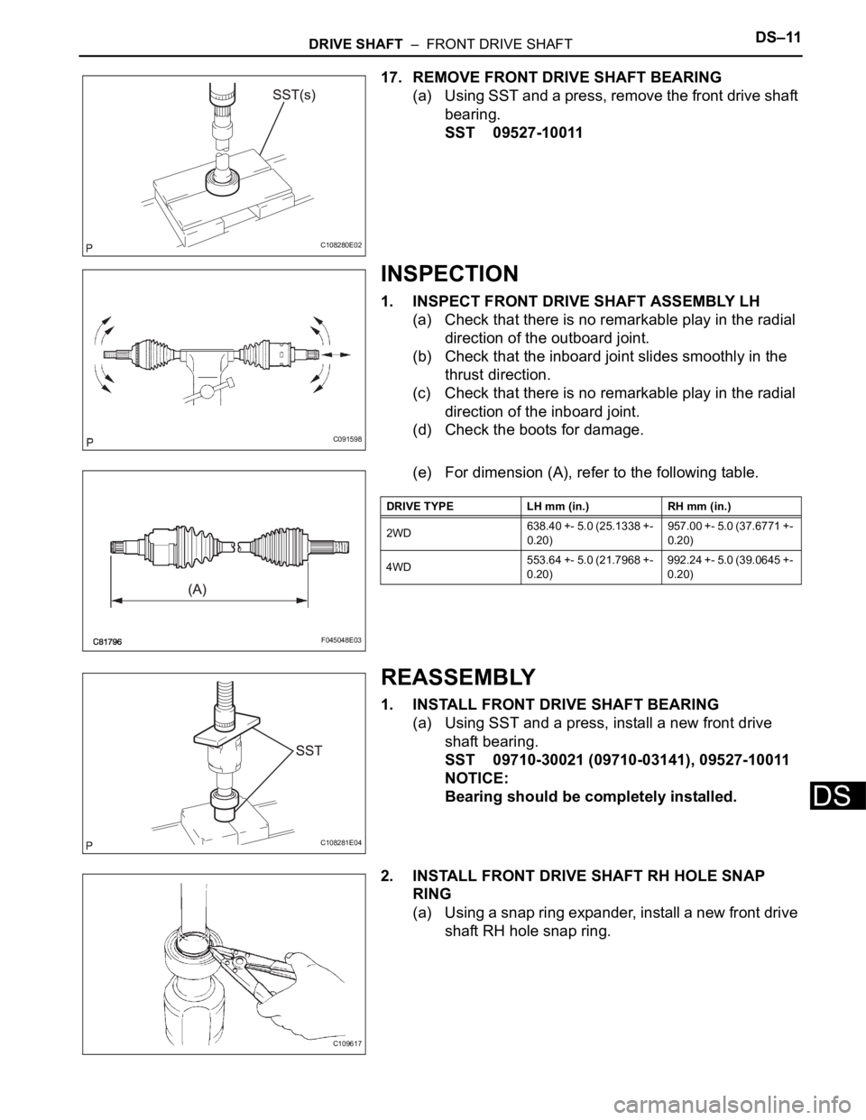
17. REMOVE FRONT DRIVE SHAFT BEARING
(a) Using SST and a press, remove the front drive shaft
bearing.
SST 09527-10011
INSPECTION
1. INSPECT FRONT DRIVE SHAFT ASSEMBLY LH
(a) Check that there is no remarkable play in the radial
direction of the outboard joint.
(b) Check that the inboard joint slides smoothly in the
thrust direction.
(c) Check that there is no remarkable play in the radial
direction of the inboard joint.
(d) Check the boots for damage.
(e) For dimension (A), refer to the following table.
REASSEMBLY
1. INSTALL FRONT DRIVE SHAFT BEARING
(a) Using SST and a press, install a new front drive
shaft bearing.
SST 09710-30021 (09710-03141), 09527-10011
NOTICE:
Bearing should be completely installed.
2. INSTALL FRONT DRIVE SHAFT RH HOLE SNAP
RING
(a) Using a snap ring expander, install a new front drive
shaft RH hole snap ring.
C108280E02
C091598
F045048E03
DRIVE TYPE LH mm (in.) RH mm (in.)
2WD638.40 +- 5.0 (25.1338 +-
0.20)957.00 +- 5.0 (37.6771 +-
0.20)
4WD553.64 +- 5.0 (21.7968 +-
0.20)992.24 +- 5.0 (39.0645 +-
0.20)
C108281E04
C109617