2007 TOYOTA SIENNA brakes
[x] Cancel search: brakesPage 110 of 3000

DRIVE SHAFT – FRONT DRIVE SHAFTDS–5
DS
REMOVAL
1. DRAIN AUTOMATIC TRANSAXLE FLUID
(a) Remove the drain plug, gasket and drain ATF.
(b) Install a new gasket and the drain plug.
Torque: 49 N*m (500 kgf*cm, 36 ft.*lbf)
2. DRAIN TRANSFER OIL (for 4WD)
HINT:
(See page TF-8)
3. REMOVE FRONT WHEEL
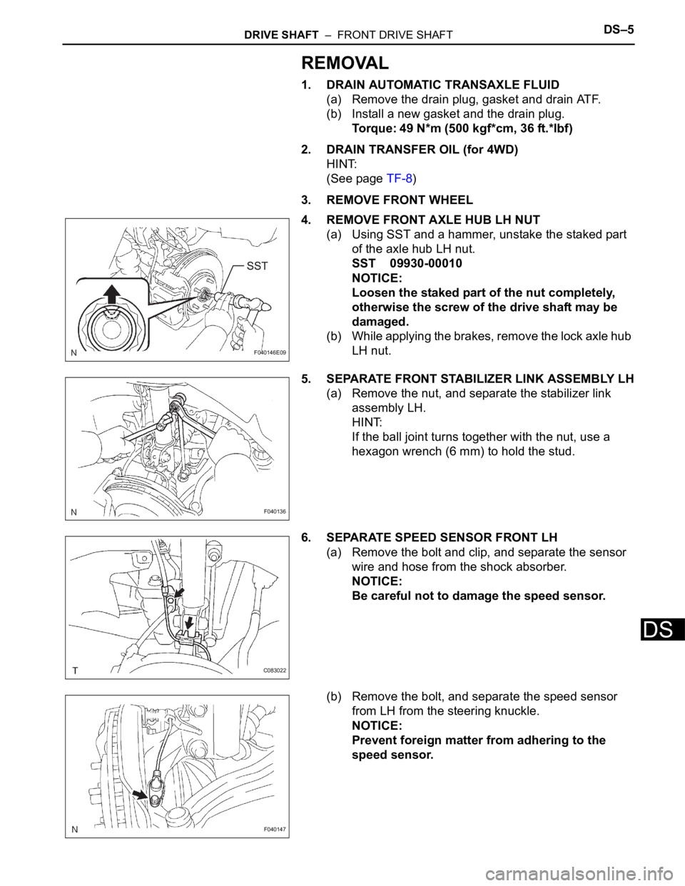
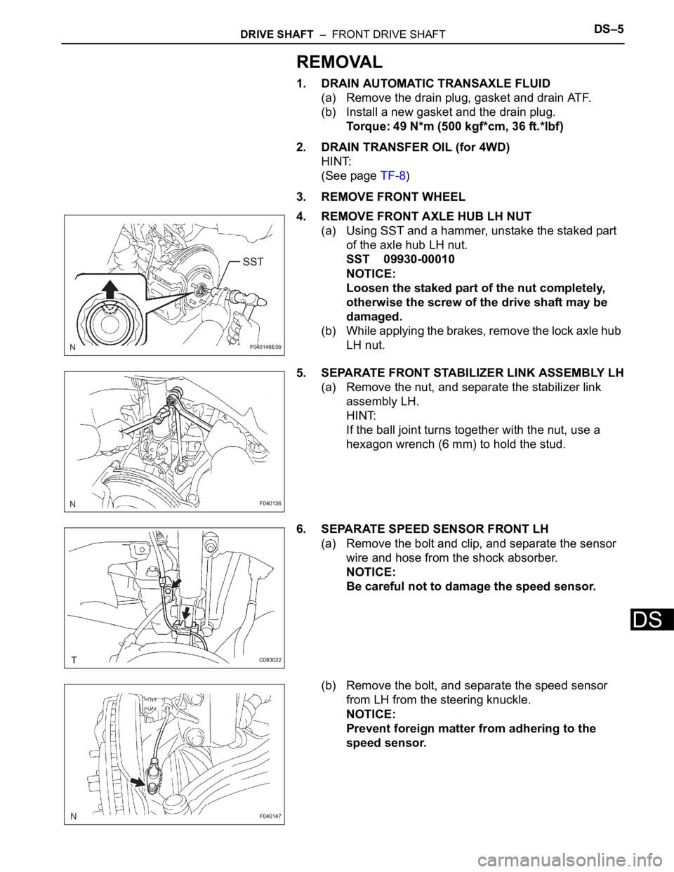
4. REMOVE FRONT AXLE HUB LH NUT
(a) Using SST and a hammer, unstake the staked part
of the axle hub LH nut.
SST 09930-00010
NOTICE:
Loosen the staked part of the nut completely,
otherwise the screw of the drive shaft may be
damaged.
(b) While applying the brakes, remove the lock axle hub
LH nut.
5. SEPARATE FRONT STABILIZER LINK ASSEMBLY LH
(a) Remove the nut, and separate the stabilizer link
assembly LH.
HINT:
If the ball joint turns together with the nut, use a
hexagon wrench (6 mm) to hold the stud.
6. SEPARATE SPEED SENSOR FRONT LH
(a) Remove the bolt and clip, and separate the sensor
wire and hose from the shock absorber.
NOTICE:
Be careful not to damage the speed sensor.
(b) Remove the bolt, and separate the speed sensor
from LH from the steering knuckle.
NOTICE:
Prevent foreign matter from adhering to the
speed sensor.
F040146E09
F040136
C083022
F040147
Page 1429 of 3000

U151E AUTOMATIC TRANSAXLE – AUTOMATIC TRANSAXLE SYSTEMAX–63
AX
DESCRIPTION
The purpose of this circuit is to prevent the engine from stalling while driving in lock-up condition when
brakes are suddenly applied.
When the brake pedal is depressed, this switch sends a signals to the ECM. Then the ECM cancels the
operation of the lock-up clutch while braking is in progress.
MONITOR DESCRIPTION
This DTC indicates that the stop light switch remains on. When the stop light switch remains ON during
"stop and go" driving, the ECM interprets this as a fault in the stop light switch and the MIL comes on and
the ECM stores the DTC. The vehicle must stop (less than 3 km/h (2 mph)) and go (30 km/h (19 mph) or
more) 5 times for two driving cycles in order to detect a malfunction.
MONITOR STRATEGY
TYPICAL ENABLING CONDITIONS
TYPICAL MALFUNCTION THRESHOLDS
DTC P0724 Brake Switch "B" Circuit High
DTC No. DTC Detection Condition Trouble Area
P0724The stop light switch remains ON even when the
vehicle is driven in a STOP (less than 3 km/h (2 mph)
and GO (30 km/h (19 mph) or more) fashion 5 times. (2-
trip detection logic).• Short in stop light switch circuit
• Stop light switch
•ECM
Related DTCs P0724: Stop light switch/Rationality
Required sensors/Components Stop light switch, Vehicle speed sensor
Frequency of operation Continuous
Duration GO and STOP 5 times
MIL operation 2 driving cycles
Sequence of operation None
The monitor will run whenever this DTC is not present. None
Ignition switchON
Sta r t e rOFF
Battery voltage8 V or more
GO (Vehicle speed is 30 km/h (18.63 mph) or more) Once
STOP (Vehicle speed is less than 3 km/h (1.86 mph)) Once
Brake switch Remain ON during GO and STOP 5 times
Page 1735 of 3000

U151F AUTOMATIC TRANSAXLE – AUTOMATIC TRANSAXLE SYSTEMAX–63
AX
DESCRIPTION
The purpose of this circuit is to prevent the engine from stalling while driving in lock-up condition when
brakes are suddenly applied.
When the brake pedal is depressed, this switch sends a signals to the ECM. Then the ECM cancels the
operation of the lock-up clutch while braking is in progress.
MONITOR DESCRIPTION
This DTC indicates that the stop light switch remains on. When the stop light switch remains ON during
"stop and go" driving, the ECM interprets this as a fault in the stop light switch and the MIL comes on and
the ECM stores the DTC. The vehicle must stop (less than 3 km/h (2 mph)) and go (30 km/h (19 mph) or
more) 5 times for two driving cycles in order to detect a malfunction.
MONITOR STRATEGY
TYPICAL ENABLING CONDITIONS
TYPICAL MALFUNCTION THRESHOLDS
DTC P0724 Brake Switch "B" Circuit High
DTC No. DTC Detection Condition Trouble Area
P0724The stop light switch remains ON even when the
vehicle is driven in a STOP (less than 3 km/h (2 mph)
and GO (30 km/h (19 mph) or more) fashion 5 times. (2-
trip detection logic).• Short in stop light switch circuit
• Stop light switch
•ECM
Related DTCs P0724: Stop light switch/Rationality
Required sensors/Components Stop light switch, Vehicle speed sensor
Frequency of operation Continuous
Duration GO and STOP 5 times
MIL operation 2 driving cycles
Sequence of operation None
The monitor will run whenever this DTC is not present. None
Ignition switchON
Sta r t e rOFF
Battery voltage8 V or more
GO (Vehicle speed is 30 km/h (18.63 mph) or more) Once
STOP (Vehicle speed is less than 3 km/h (1.86 mph)) Once
Brake switch Remain ON during GO and STOP 5 times
Page 2075 of 3000

DS–22DRIVE SHAFT – REAR DRIVE SHAFT (for 4WD)
DS
REMOVAL
1. REMOVE REAR WHEEL
2. REMOVE TAIL EXHAUST PIPE ASSEMBLY (See page
EX-8)
3. SEPARATE REAR SPEED SENSOR
(a) Remove the bolt and the speed sensor from the
axle carrier.
NOTICE:
• Be careful not to damage the speed sensor.
• Prevent foreign matter from adhering to the
speed sensor.
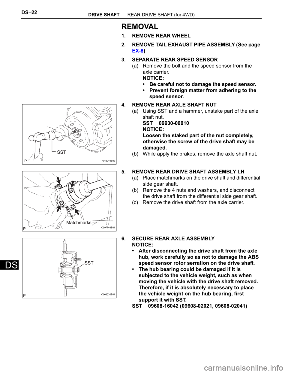
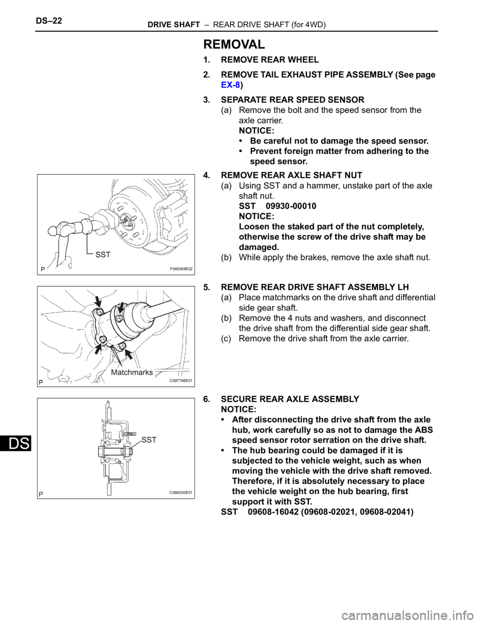
4. REMOVE REAR AXLE SHAFT NUT
(a) Using SST and a hammer, unstake part of the axle
shaft nut.
SST 09930-00010
NOTICE:
Loosen the staked part of the nut completely,
otherwise the screw of the drive shaft may be
damaged.
(b) While apply the brakes, remove the axle shaft nut.
5. REMOVE REAR DRIVE SHAFT ASSEMBLY LH
(a) Place matchmarks on the drive shaft and differential
side gear shaft.
(b) Remove the 4 nuts and washers, and disconnect
the drive shaft from the differential side gear shaft.
(c) Remove the drive shaft from the axle carrier.
6. SECURE REAR AXLE ASSEMBLY
NOTICE:
• After disconnecting the drive shaft from the axle
hub, work carefully so as not to damage the ABS
speed sensor rotor serration on the drive shaft.
• The hub bearing could be damaged if it is
subjected to the vehicle weight, such as when
moving the vehicle with the drive shaft removed.
Therefore, if it is absolutely necessary to place
the vehicle weight on the hub bearing, first
support it with SST.
SST 09608-16042 (09608-02021, 09608-02041)
F045049E02
C097746E01
C066030E01
Page 2080 of 3000

DRIVE SHAFT – FRONT DRIVE SHAFTDS–5
DS
REMOVAL
1. DRAIN AUTOMATIC TRANSAXLE FLUID
(a) Remove the drain plug, gasket and drain ATF.
(b) Install a new gasket and the drain plug.
Torque: 49 N*m (500 kgf*cm, 36 ft.*lbf)
2. DRAIN TRANSFER OIL (for 4WD)
HINT:
(See page TF-8)
3. REMOVE FRONT WHEEL
4. REMOVE FRONT AXLE HUB LH NUT
(a) Using SST and a hammer, unstake the staked part
of the axle hub LH nut.
SST 09930-00010
NOTICE:
Loosen the staked part of the nut completely,
otherwise the screw of the drive shaft may be
damaged.
(b) While applying the brakes, remove the lock axle hub
LH nut.
5. SEPARATE FRONT STABILIZER LINK ASSEMBLY LH
(a) Remove the nut, and separate the stabilizer link
assembly LH.
HINT:
If the ball joint turns together with the nut, use a
hexagon wrench (6 mm) to hold the stud.
6. SEPARATE SPEED SENSOR FRONT LH
(a) Remove the bolt and clip, and separate the sensor
wire and hose from the shock absorber.
NOTICE:
Be careful not to damage the speed sensor.
(b) Remove the bolt, and separate the speed sensor
from LH from the steering knuckle.
NOTICE:
Prevent foreign matter from adhering to the
speed sensor.
F040146E09
F040136
C083022
F040147
Page 2097 of 3000

DS–22DRIVE SHAFT – REAR DRIVE SHAFT (for 4WD)
DS
REMOVAL
1. REMOVE REAR WHEEL
2. REMOVE TAIL EXHAUST PIPE ASSEMBLY (See page
EX-8)
3. SEPARATE REAR SPEED SENSOR
(a) Remove the bolt and the speed sensor from the
axle carrier.
NOTICE:
• Be careful not to damage the speed sensor.
• Prevent foreign matter from adhering to the
speed sensor.
4. REMOVE REAR AXLE SHAFT NUT
(a) Using SST and a hammer, unstake part of the axle
shaft nut.
SST 09930-00010
NOTICE:
Loosen the staked part of the nut completely,
otherwise the screw of the drive shaft may be
damaged.
(b) While apply the brakes, remove the axle shaft nut.
5. REMOVE REAR DRIVE SHAFT ASSEMBLY LH
(a) Place matchmarks on the drive shaft and differential
side gear shaft.
(b) Remove the 4 nuts and washers, and disconnect
the drive shaft from the differential side gear shaft.
(c) Remove the drive shaft from the axle carrier.
6. SECURE REAR AXLE ASSEMBLY
NOTICE:
• After disconnecting the drive shaft from the axle
hub, work carefully so as not to damage the ABS
speed sensor rotor serration on the drive shaft.
• The hub bearing could be damaged if it is
subjected to the vehicle weight, such as when
moving the vehicle with the drive shaft removed.
Therefore, if it is absolutely necessary to place
the vehicle weight on the hub bearing, first
support it with SST.
SST 09608-16042 (09608-02021, 09608-02041)
F045049E02
C097746E01
C066030E01
Page 2598 of 3000

BR–6BRAKE – BRAKE FLUID
BR
(f) Bleed the air from the pressure reduction line
according to "Step 3: Decrease" on the intelligent
tester display.
NOTICE:
• Bleed the pressure reduction line by
following the steps displayed on the
intelligent tester.
• Make sure that the master cylinder reservoir
tank does not become empty of brake fluid.
(1) Connect a vinyl tube to either one of the
bleeder plugs.
(2) Loosen the bleeder plug (*11).
(3) Using the intelligent tester, operate the brake
actuator assembly, completely depress the
brake pedal, and hold it.
NOTICE:
• The operation stops automatically in 4
seconds. When performing this
procedure continuously, an interval of at
least 20 seconds is required.
• When the operation is completed, the
brake pedal goes down slightly. This is a
normal phenomenon when the solenoid
opens.
• During this procedure, the pedal seems
heavy, but completely depress it so that
the brake fluid comes out from the
bleeder plug.
• Be sure to keep the brake pedal
depressed. Never depress and release
the pedal repeatedly.
(4) Tighten the bleeder plug, then release the
brake pedal (*12).
(5) Repeat (*11) to (*12) until all the air in the fluid
is completely bled out.
(6) Tighten the bleeder plug completely.
Torque: Disc
8.3 N*m (85 kgf*cm, 73 in.*lbf)
Drum
11 N*m (112 kgf*cm, 8 ft.*lbf)
(7) Repeat the above procedures for the rest of the
brakes to bleed the air from the brake line.
(g) Bleed the air from the brake line again according to
"Step 4: Increase" on the intelligent tester display.
NOTICE:
• Bleed the brake line by following the steps
displayed on the intelligent tester.
• Make sure that the master cylinder reservoir
tank does not become empty of brake fluid.
(1) Connect a vinyl tube to either one of the
bleeder plugs.
(2) Depress the brake pedal several times, then
loosen the bleeder plug connected to the vinyl
tube with the pedal depressed (*13).