2007 TOYOTA SIENNA window
[x] Cancel search: windowPage 14 of 3000

PP–82PREPARATION – WINDSHIELD / WINDOWGLASS
PP
SSM
08850-00801 Windshield Glass Adhesive Set
or equivalent
Page 51 of 3000

INTRODUCTION – HOW TO TROUBLESHOOT ECU CONTROLLED SYSTEMSIN–39
IN
• In the DTC check, it is very important to determine
whether the problem indicated by the DTC either: 1)
still occurs, or 2) occurred in the past but has returned
to normal. In addition, the DTC should be compared
to the problem symptom to see if they are related. For
this reason, DTCs should be checked before and after
confirmation of symptoms (i.e., whether or not
problem symptoms exist) to determine current system
conditions, as shown in the flowchart below.
• Never skip the DTC check. Failing to check DTCs
may, depending on the case, result in unnecessary
troubleshooting for systems operating normally or
lead to repairs not related to the problem. Follow the
procedures listed in the flowchart in the correct order.
Theft Deterrent System XXXXX
Engine Immobiliser System
XX
Cruise Control SystemXXX
Dynamic Laser Cruise Control System
XXX
Lighting System
XX
Wiper and Washer SystemXXXXX
Power Door Lock Control System X X X
Wireless Door Lock Control SystemXX
Key Reminder Warning System X X XX
Meter / Gauge System X X X
Audio and Visual SystemXXXX
Rear Seat Entertainment System XXXXX
Navigation System
XXXX
Clearance Sonar SystemXXXXX
Rear View Monitor System XXXXX
Power Window Control System (with Jam
Protection Function)XXX
Power Window Control System (without Jam
Protection Function)XXXXX
Power Mirror Control System (with Memory) X X X
Power Mirror Control System (without Memory)XXXXX
Front Power Seat Control System X X X
Rear No. 2 Seat Assembly (with Power Stowing
Function)XXXXX
Window Deogger SystemXXXXX
Power Slide Door System
XX
Slide Door Closer System X X X
Back Door Closer SystemXX
Power Back Door SystemXX
Sliding Roof System XXXXX
Multiplex Communication System XXXXX
CAN Communication System XXXXXSystemSYMPTOM CONFIRMATION AND DIAGNOSTIC TROUBLE CODE
DTC Check
(Normal Mode)DTC Check
(Check Mode)Sensor Check/
Test Mode
(Input Signal
Check)Data List Active Test
Page 55 of 3000
INTRODUCTION – HOW TO TROUBLESHOOT ECU CONTROLLED SYSTEMSIN–43
IN
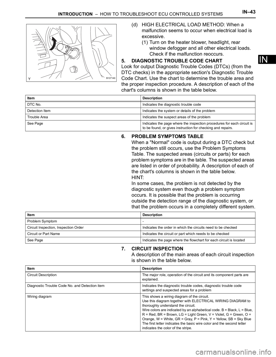
(d) HIGH ELECTRICAL LOAD METHOD: When a
malfunction seems to occur when electrical load is
excessive.
(1) Turn on the heater blower, headlight, rear
window defogger and all other electrical loads.
Check if the malfunction reoccurs.
5. DIAGNOSTIC TROUBLE CODE CHART
Look for output Diagnostic Trouble Codes (DTCs) (from the
DTC checks) in the appropriate section's Diagnostic Trouble
Code Chart. Use the chart to determine the trouble area and
the proper inspection procedure. A description of each of the
chart's columns is shown in the table below.
6. PROBLEM SYMPTOMS TABLE
When a "Normal" code is output during a DTC check but
the problem still occurs, use the Problem Symptoms
Table. The suspected areas (circuits or parts) for each
problem symptoms are in the table. The suspected areas
are listed in order of probability. A description of each of
the chart's columns is shown in the table below.
HINT:
In some cases, the problem is not detected by the
diagnostic system even though a problem symptom
occurs. It is possible that the problem is occurring
outside the detection range of the diagnostic system, or
that the problem occurs in a completely different system.
7. CIRCUIT INSPECTION
A description of the main areas of each circuit inspection
is shown in the table below.
B107149
Item Description
DTC No. Indicates the diagnostic trouble code
Detection Item Indicates the system or details of the problem
Trouble Area Indicates the suspect areas of the problem
See Page Indicates the page where the inspection procedures for each circuit is
to be found, or gives instruction for checking and repairs.
Item Description
Problem Symptom -
Circuit Inspection, Inspection Order Indicates the order in which the circuits need to be checked
Circuit or Part Name Indicates the circuit or part which needs to be checked
See Page Indicates the page where the flowchart for each circuit is located
Item Description
Circuit Description The major role, operation of the circuit and its component parts are
explained.
Diagnostic Trouble Code No. and Detection item Indicates the diagnostic trouble codes, diagnostic trouble code
settings and suspected areas for a problem
Wiring diagram This shows a wiring diagram of the circuit.
Use this diagram together with ELECTRICAL WIRING DIAGRAM to
thoroughly understand the circuit.
Wire colors are indicated by an alphabetical code. B = Black, L = Blue,
R = Red, BR = Brown, LG = Light Green, V = Violet, G = Green, O =
Orange, W = White, GR = Gray, P = Pink, Y = Yellow, SB = Sky Blue
The first letter indicates the basic wire color and the second letter
indicates the color of the stripe.
Page 69 of 3000

INTRODUCTION – HOW TO TROUBLESHOOT ECU CONTROLLED SYSTEMSIN–39
IN
• In the DTC check, it is very important to determine
whether the problem indicated by the DTC either: 1)
still occurs, or 2) occurred in the past but has returned
to normal. In addition, the DTC should be compared
to the problem symptom to see if they are related. For
this reason, DTCs should be checked before and after
confirmation of symptoms (i.e., whether or not
problem symptoms exist) to determine current system
conditions, as shown in the flowchart below.
• Never skip the DTC check. Failing to check DTCs
may, depending on the case, result in unnecessary
troubleshooting for systems operating normally or
lead to repairs not related to the problem. Follow the
procedures listed in the flowchart in the correct order.
Theft Deterrent System XXXXX
Engine Immobiliser System
XX
Cruise Control SystemXXX
Dynamic Laser Cruise Control System
XXX
Lighting System
XX
Wiper and Washer SystemXXXXX
Power Door Lock Control System X X X
Wireless Door Lock Control SystemXX
Key Reminder Warning System X X XX
Meter / Gauge System X X X
Audio and Visual SystemXXXX
Rear Seat Entertainment System XXXXX
Navigation System
XXXX
Clearance Sonar SystemXXXXX
Rear View Monitor System XXXXX
Power Window Control System (with Jam
Protection Function)XXX
Power Window Control System (without Jam
Protection Function)XXXXX
Power Mirror Control System (with Memory) X X X
Power Mirror Control System (without Memory)XXXXX
Front Power Seat Control System X X X
Rear No. 2 Seat Assembly (with Power Stowing
Function)XXXXX
Window Deogger SystemXXXXX
Power Slide Door System
XX
Slide Door Closer System X X X
Back Door Closer SystemXX
Power Back Door SystemXX
Sliding Roof System XXXXX
Multiplex Communication System XXXXX
CAN Communication System XXXXXSystemSYMPTOM CONFIRMATION AND DIAGNOSTIC TROUBLE CODE
DTC Check
(Normal Mode)DTC Check
(Check Mode)Sensor Check/
Test Mode
(Input Signal
Check)Data List Active Test
Page 73 of 3000
INTRODUCTION – HOW TO TROUBLESHOOT ECU CONTROLLED SYSTEMSIN–43
IN
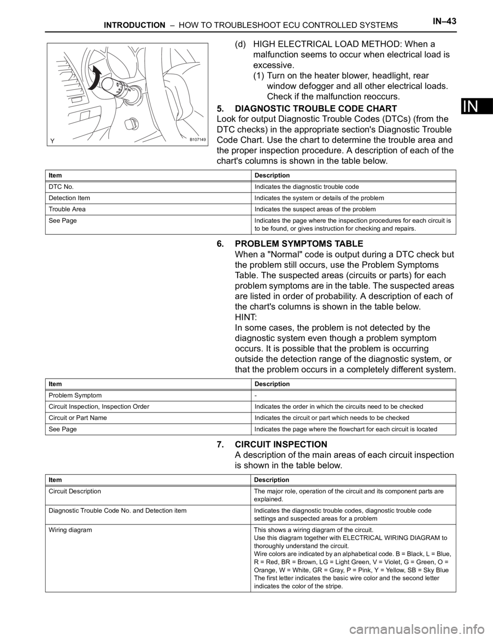
(d) HIGH ELECTRICAL LOAD METHOD: When a
malfunction seems to occur when electrical load is
excessive.
(1) Turn on the heater blower, headlight, rear
window defogger and all other electrical loads.
Check if the malfunction reoccurs.
5. DIAGNOSTIC TROUBLE CODE CHART
Look for output Diagnostic Trouble Codes (DTCs) (from the
DTC checks) in the appropriate section's Diagnostic Trouble
Code Chart. Use the chart to determine the trouble area and
the proper inspection procedure. A description of each of the
chart's columns is shown in the table below.
6. PROBLEM SYMPTOMS TABLE
When a "Normal" code is output during a DTC check but
the problem still occurs, use the Problem Symptoms
Table. The suspected areas (circuits or parts) for each
problem symptoms are in the table. The suspected areas
are listed in order of probability. A description of each of
the chart's columns is shown in the table below.
HINT:
In some cases, the problem is not detected by the
diagnostic system even though a problem symptom
occurs. It is possible that the problem is occurring
outside the detection range of the diagnostic system, or
that the problem occurs in a completely different system.
7. CIRCUIT INSPECTION
A description of the main areas of each circuit inspection
is shown in the table below.
B107149
Item Description
DTC No. Indicates the diagnostic trouble code
Detection Item Indicates the system or details of the problem
Trouble Area Indicates the suspect areas of the problem
See Page Indicates the page where the inspection procedures for each circuit is
to be found, or gives instruction for checking and repairs.
Item Description
Problem Symptom -
Circuit Inspection, Inspection Order Indicates the order in which the circuits need to be checked
Circuit or Part Name Indicates the circuit or part which needs to be checked
See Page Indicates the page where the flowchart for each circuit is located
Item Description
Circuit Description The major role, operation of the circuit and its component parts are
explained.
Diagnostic Trouble Code No. and Detection item Indicates the diagnostic trouble codes, diagnostic trouble code
settings and suspected areas for a problem
Wiring diagram This shows a wiring diagram of the circuit.
Use this diagram together with ELECTRICAL WIRING DIAGRAM to
thoroughly understand the circuit.
Wire colors are indicated by an alphabetical code. B = Black, L = Blue,
R = Red, BR = Brown, LG = Light Green, V = Violet, G = Green, O =
Orange, W = White, GR = Gray, P = Pink, Y = Yellow, SB = Sky Blue
The first letter indicates the basic wire color and the second letter
indicates the color of the stripe.
Page 251 of 3000
WIPER AND WASHER – FRONT WIPER MOTORWW–7
WW
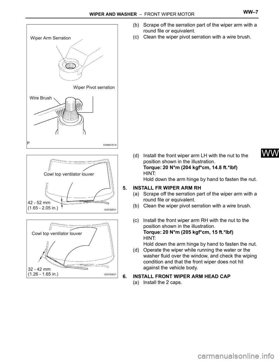
(b) Scrape off the serration part of the wiper arm with a
round file or equivalent.
(c) Clean the wiper pivot serration with a wire brush.
(d) Install the front wiper arm LH with the nut to the
position shown in the illustration.
Torque: 20 N*m (204 kgf*cm, 14.8 ft.*lbf)
HINT:
Hold down the arm hinge by hand to fasten the nut.
5. INSTALL FR WIPER ARM RH
(a) Scrape off the serration part of the wiper arm with a
round file or equivalent.
(b) Clean the wiper pivot serration with a wire brush.
(c) Install the front wiper arm RH with the nut to the
position shown in the illustration.
Torque: 20 N*m (205 kgf*cm, 15 ft.*lbf)
HINT:
Hold down the arm hinge by hand to fasten the nut.
(d) Operate the wiper while running the water or the
washer fluid over the window, and check the wiping
condition and that the front wiper does not hit
against the vehicle body.
6. INSTALL FRONT WIPER ARM HEAD CAP
(a) Install the 2 caps.
E058837E18
I035782E01
I035783E01
Page 257 of 3000
AUDIO / VISUAL – AUDIO AND VISUAL SYSTEMAV – 5
AV
• Keep the discs away from direct sunlight.
(Exposure to direct sunlight may cause
deformation of the disc, making the disc
unusable.)
• Do not use odd-shaped CDs because these
may cause player malfunctions.
• Do not use discs whose recording portion is
transparent or translucent because they may
not be inserted, ejected, or played normally.
HINT:
• When it is cold or it is raining, if the windows mist
up, mist and also dew may form in the player. In
such a case, the CD may skip or the CD may
stop in the middle of play. Ventilate or dehumidify
the cabin for a while before using the player.
• The CD may skip if the player experiences strong
vibrations when the vehicle is driven on rough
road or similar uneven surface(s).
(d) Cleaning
NOTICE:
Do not use a lens cleaner because it may cause
a malfunction in the pickup portion of the player.
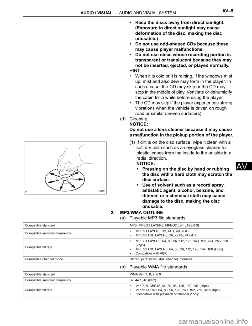
(1) If dirt is on the disc surface, wipe it clean with a
soft dry cloth such as an eyeglass cleaner for
plastic lenses from the inside to the outside in a
radial direction.
NOTICE:
• Pressing on the disc by hand or rubbing
the disc with a hard cloth may scratch the
disc surface.
• Use of solvent such as a record spray,
antistatic agent, alcohol, benzine, and
thinner, or a chemical cloth may cause
damage to the disc, making the disc
unusable.
2. MP3/WMA OUTLINE
(a) Playable MP3 file standards
(b) Playable WMA file standards
I100151
Compatible standard MP3 (MPEG1 LAYER3, MPEG2 LSF LAYER 3)
Compatible sampling frequency• MPEG1 LAYER3: 32, 44.1, 48 (kHz)
• MPEG2 LSF LAYER3: 36, 22.05, 24 (kHz)
Compatible bit rate• MPEG1 LAYER3: 64, 80, 96, 112, 128, 160, 192, 224, 256, 320
(kbps)
• MPEG2 LSF LAYER3: 64, 80, 96, 112, 128, 144, 160 (kbps)
• Compatible with VBR
Compatible channel mode Stereo, joint stereo, dual channel, monaural
Compatible standard WMA Ver. 7, 8, and 9
Compatible sampling frequency 32, 44.1, 48 (kHz)
Compatible bit rate• Ver. 7, 8: CBR48, 64, 80, 96, 128, 160, 192 (kbps)
• Ver. 9: CBR48, 64, 80, 96, 128, 160, 192, 256, 320 (kbps)
• Compatible with playback of channel 2 only
Page 272 of 3000
NAVIGATION – NAVIGATION SYSTEMNS–11
NS
• Leaving the disc exposed halfway out of the
slot for a long time after pressing the disc
eject button may cause deformation of the
disc, making the disc unusable.
• If discs have adhesive tape, stickers, CDR
labels, or any traces of such labels attached,
the discs may not be ejected or player
malfunctions may result.
• Keep the discs away from direct sunlight.
(Exposure to direct sunlight may cause
deformation of the disc, making the disc
unusable.)
• Do not use odd-shaped CDs because these
may cause player malfunctions.
• Do not use discs whose recording portion is
transparent or translucent because they may
not be inserted, ejected, or played normally.
HINT:
• When it is cold or it is raining, if the windows mist
up, mist and also dew may form in the player. In
such a case, the CD may skip or the CD may
stop in the middle of play. Ventilate or dehumidify
the cabin for a while before using the player.
• The CD may skip if the player experiences strong
vibrations when the vehicle is driven on rough
road or similar uneven surface(s).
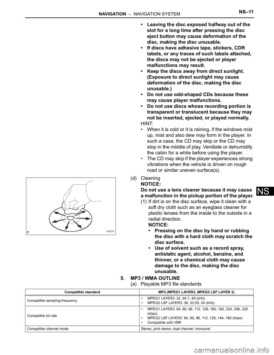
(d) Cleaning
NOTICE:
Do not use a lens cleaner because it may cause
a malfunction in the pickup portion of the player.
(1) If dirt is on the disc surface, wipe it clean with a
soft dry cloth such as an eyeglass cleaner for
plastic lenses from the inside to the outside in a
radial direction.
NOTICE:
• Pressing on the disc by hand or rubbing
the disc with a hard cloth may scratch the
disc surface.
• Use of solvent such as a record spray,
antistatic agent, alcohol, benzine, and
thinner, or a chemical cloth may cause
damage to the disc, making the disc
unusable.
5. MP3 / WMA OUTLINE
(a) Playable MP3 file standards
I100151
Compatible standard MP3 (MPEG1 LAYER3, MPEG2 LSF LAYER 3)
Compatible sampling frequency• MPEG1 LAYER3: 32, 44.1, 48 (kHz)
• MPEG2 LSF LAYER3: 36, 22.05, 24 (kHz)
Compatible bit rate• MPEG1 LAYER3: 64, 80, 96, 112, 128, 160, 192, 224, 256, 320
(kbps)
• MPEG2 LSF LAYER3: 64, 80, 96, 112, 128, 144, 160 (kbps)
• Compatible with VBR
Compatible channel mode Stereo, joint stereo, dual channel, monaural