2007 TOYOTA SIENNA oil change
[x] Cancel search: oil changePage 130 of 3000

PP–16PREPARATION – 2GR-FE LUBRICATION
PP
LUBRICANT
Item Condition Capacity Classification
Oil grade - - 5W-30: API grade SL Energy-
Conserving, SM Energy-
Conserving or ILSAC multigrade
engine oil
Drain and refill with oil filter change 6.1 liters (6.4 US qts, 5.4 Imp.
qts)-
without oil filter change 5.7 liters (6.0 US qts, 5.0 Imp.
qts)-
Dry fill Dry fill 7.1 liters (7.5 US qts, 6.2Imp. qts) -
Page 394 of 3000

ES–882GR-FE ENGINE CONTROL SYSTEM – SFI SYSTEM
ES
HINT:
If DTC P0011, P0012, P0021 or P0022 is present, check the VVT (Variable Valve Timing) system.
DESCRIPTION
Refer to DTC P0010 (See page ES-75).
MONITOR DESCRIPTION
The ECM optimizes the intake valve timing using the VVT (Variable Valve Timing) system to control the
intake camshaft. The VVT system includes the ECM, the Oil Control Valve (OCV) and the VVT controller.
The ECM sends a target duty-cycle control signal to the OCV. This control signal regulates the oil
pressure applied to the VVT controller. The VVT controller can advance or retard the intake camshaft.
If the difference between the target and actual intake valve timings is large, and changes in actual intake
valve timing are small, the ECM interprets this as the VVT controller stuck malfunction and sets a DTC.
Example:
A DTC will be set when the following conditions 1), 2) and 3) are met:
1) The difference between the target and actual intake valve timings is more than 5
CA (Crankshaft
Angle) and the condition continues for more than 4.5 seconds.
2) It takes 5 seconds or more to change the valve timing by 5
CA.
DTC P0011Camshaft Position "A" - Timing Over-Advanced
or System Performance (Bank 1)
DTC P0012Camshaft Position "A" - Timing Over-Retarded
(Bank 1)
DTC P0021Camshaft Position "A" - Timing Over-Advanced
or System Performance (Bank 2)
DTC P0022Camshaft Position "A" - Timing Over-Retarded
(Bank 2)
DTC No. DTC Detection Condition Trouble Area
P0011
P0021Advanced cam timing:
With warm engine and engine speed of between 500
rpm and 4000 rpm, all conditions (a), (b) and (c) are
met (1 trip detection logic):
(a) Difference between target and actual intake valve
timings is more than 5
CA (Crankshaft Angle) for 4.5
seconds
(b) Current intake valve timing is fixed (timing changes
less than 5
CA in 5 seconds)
(c) Variations in VVT controller timing are more than 19
CA of maximum delayed timing (advanced)• Valve timing
• OCV for intake camshaft
• OCV filter
• Intake camshaft (bank 1) timing gear assembly
•ECM
P0012
P0022Retarded cam timing:
With warm engine and engine speed of between 500
rpm and 4000 rpm, all conditions (a), (b) and (c) are
met (2 trip detection logic):
(a) Difference between target and actual intake valve
timings is more than 5
CA (Crankshaft Angle) for 4.5
seconds
(b) Current intake valve timing is fixed (timing changes
less than 5
CA in 5 seconds)
(c) Variations in VVT controller timing is 19
CA or less
of maximum delayed timing (retarded)• Valve timing
• OCV for intake camshaft
• OCV filter
• Intake camshaft (bank 2) timing gear assembly
•ECM
Page 525 of 3000
2GR-FE ENGINE CONTROL SYSTEM – SFI SYSTEMES–219
ES
OK
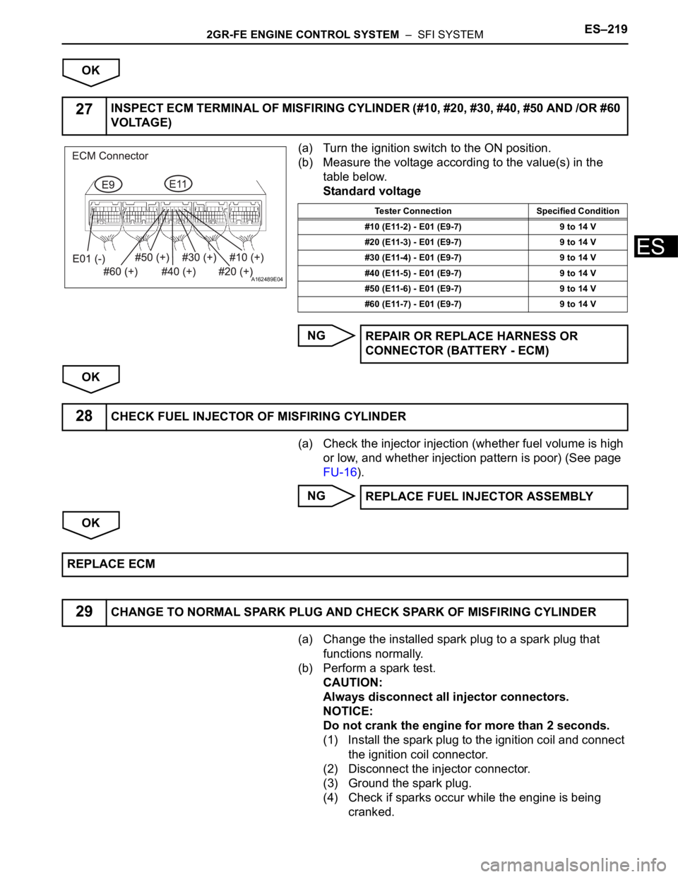
(a) Turn the ignition switch to the ON position.
(b) Measure the voltage according to the value(s) in the
table below.
Standard voltage
NG
OK
(a) Check the injector injection (whether fuel volume is high
or low, and whether injection pattern is poor) (See page
FU-16).
NG
OK
(a) Change the installed spark plug to a spark plug that
functions normally.
(b) Perform a spark test.
CAUTION:
Always disconnect all injector connectors.
NOTICE:
Do not crank the engine for more than 2 seconds.
(1) Install the spark plug to the ignition coil and connect
the ignition coil connector.
(2) Disconnect the injector connector.
(3) Ground the spark plug.
(4) Check if sparks occur while the engine is being
cranked.
27INSPECT ECM TERMINAL OF MISFIRING CYLINDER (#10, #20, #30, #40, #50 AND /OR #60
VOLTAGE)
A162489E04
Tester Connection Specified Condition
#10 (E11-2) - E01 (E9-7) 9 to 14 V
#20 (E11-3) - E01 (E9-7) 9 to 14 V
#30 (E11-4) - E01 (E9-7) 9 to 14 V
#40 (E11-5) - E01 (E9-7) 9 to 14 V
#50 (E11-6) - E01 (E9-7) 9 to 14 V
#60 (E11-7) - E01 (E9-7) 9 to 14 V
REPAIR OR REPLACE HARNESS OR
CONNECTOR (BATTERY - ECM)
28CHECK FUEL INJECTOR OF MISFIRING CYLINDER
REPLACE FUEL INJECTOR ASSEMBLY
REPLACE ECM
29CHANGE TO NORMAL SPARK PLUG AND CHECK SPARK OF MISFIRING CYLINDER
Page 526 of 3000
ES–2202GR-FE ENGINE CONTROL SYSTEM – SFI SYSTEM
ES
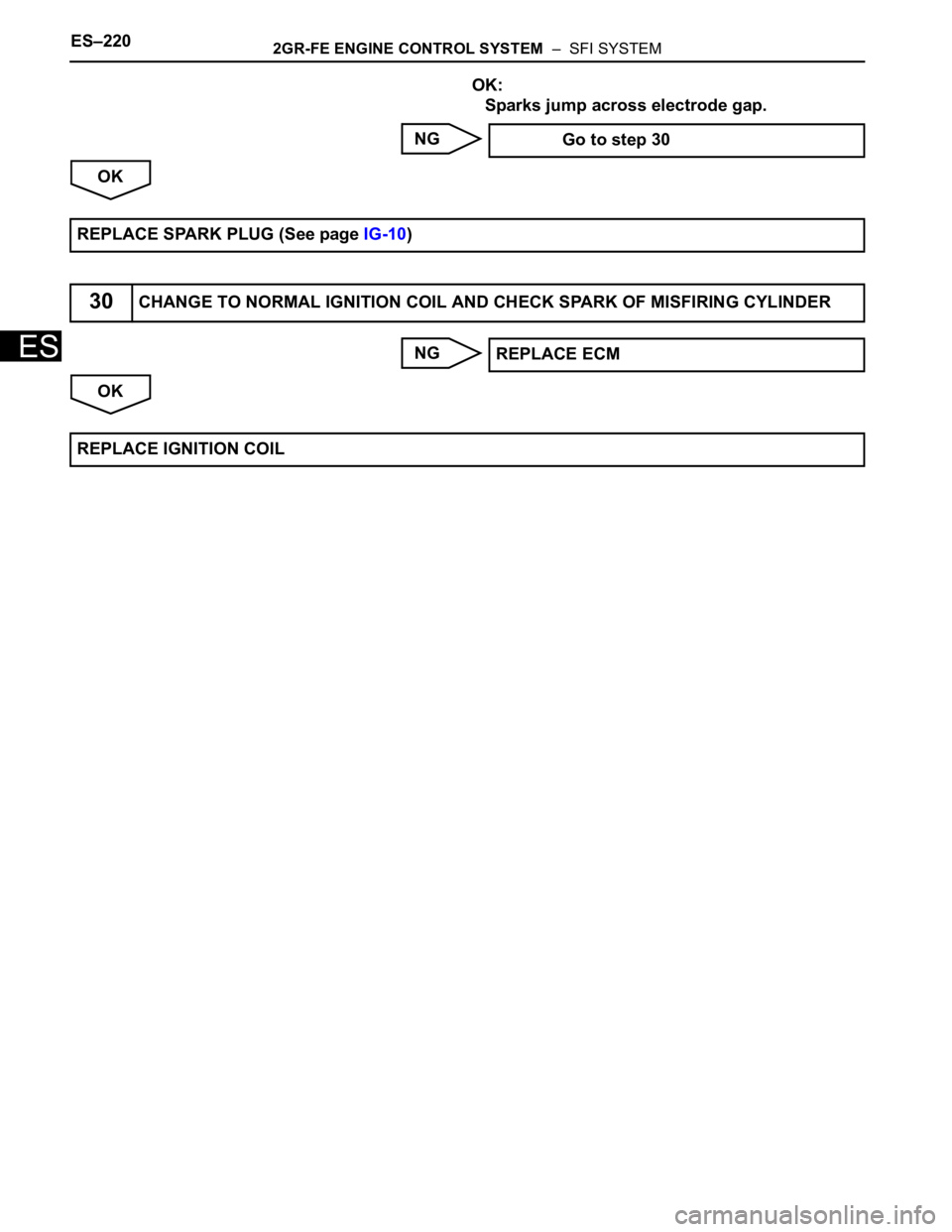
OK:
Sparks jump across electrode gap.
NG
OK
NG
OK Go to step 30
REPLACE SPARK PLUG (See page IG-10)
30CHANGE TO NORMAL IGNITION COIL AND CHECK SPARK OF MISFIRING CYLINDER
REPLACE ECM
REPLACE IGNITION COIL
Page 540 of 3000

ES–2342GR-FE ENGINE CONTROL SYSTEM – SFI SYSTEM
ES
DESCRIPTION
The intake camshaft's Variable Valve Timing (VVT) sensor (G signal) consists of a magnet and MRE
(Magneto Resistance Element).
The VVT camshaft drive gear has a sensor plate with 3 teeth on its outer circumference. When the gear
rotates, changes occur in the air gaps between the sensor plate and MRE, which affects the magnetic
field. As a result, the resistance of the MRE material fluctuates. The VVT sensor converts the gear
rotation data to pulse signals, uses the pulse signals to determine the camshaft angle, and sends it to the
ECM.
The crankshaft angle sensor plate has 34 teeth. The pickup coil generates 34 signals for each engine
revolution. Based on combination of the G signal and NE signal, the ECM detects the crankshaft angle.
Then the ECM uses this data to control fuel injection time and injection timing. Also, based on the NE
signal, the ECM detects the engine speed.
Reference: Inspection using an oscilloscope
DTC P0340Camshaft Position Sensor "A" Circuit (Bank 1
or Single Sensor)
DTC P0342Camshaft Position Sensor "A" Circuit Low
Input (Bank 1 or Single Sensor)
DTC P0343Camshaft Position Sensor "A" Circuit High
Input (Bank 1 or Single Sensor)
DTC P0345 Camshaft Position Sensor "A" Circuit (Bank 2)
DTC P0347Camshaft Position Sensor "A" Circuit Low
Input (Bank 2)
DTC P0348Camshaft Position Sensor "A" Circuit High
Input (Bank 2)
DTC No. DTC Detection Condition Trouble Area
P0340
P0345• Input voltage to ECM remains 0.3 V or less, or 4.7
V or higher for more than 5 seconds, when 2 or
more seconds have elapsed after turning ignition
switch ON (2 trip detection logic)
• No VVT sensor signal to ECM during cranking (1
trip detection logic)• Open or short in VVT sensor circuit for intake
camshaft
• VVT sensor for intake camshaft
• Camshaft timing gear for intake camshaft
• Jumped tooth of timing chain for intake camshaft
•ECM
P0342
P0347Output voltage of VVT sensor is 0.3 V or less for 5
seconds (1 trip detection logic)• Open or short in VVT sensor circuit for intake
camshaft
• VVT sensor for intake camshaft
• Camshaft timing gear for intake camshaft
• Jumped tooth of timing chain for intake camshaft
•ECM
P0343
P0348Output voltage of VVT sensor is 4.7 V or more for 5
seconds (1 trip detection logic)• Open or short in VVT sensor circuit for intake
camshaft
• VVT sensor for intake camshaft
• Camshaft timing gear for intake camshaft
• Jumped tooth of timing chain for intake camshaft
•ECM
Page 1304 of 3000
LU–62GR-FE LUBRICATION – OIL AND OIL FILTER
LU
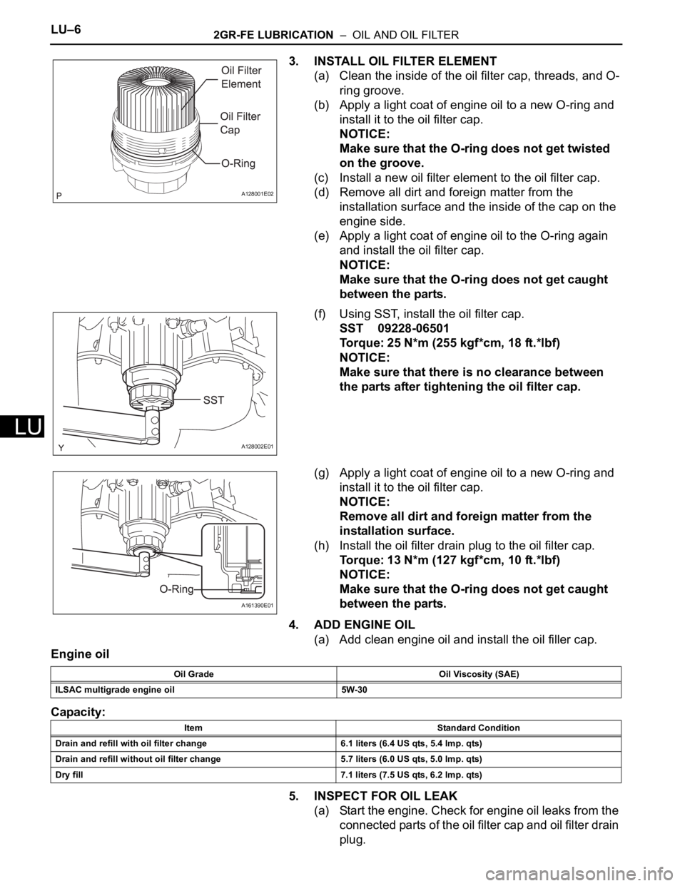
3. INSTALL OIL FILTER ELEMENT
(a) Clean the inside of the oil filter cap, threads, and O-
ring groove.
(b) Apply a light coat of engine oil to a new O-ring and
install it to the oil filter cap.
NOTICE:
Make sure that the O-ring does not get twisted
on the groove.
(c) Install a new oil filter element to the oil filter cap.
(d) Remove all dirt and foreign matter from the
installation surface and the inside of the cap on the
engine side.
(e) Apply a light coat of engine oil to the O-ring again
and install the oil filter cap.
NOTICE:
Make sure that the O-ring does not get caught
between the parts.
(f) Using SST, install the oil filter cap.
SST 09228-06501
Torque: 25 N*m (255 kgf*cm, 18 ft.*lbf)
NOTICE:
Make sure that there is no clearance between
the parts after tightening the oil filter cap.
(g) Apply a light coat of engine oil to a new O-ring and
install it to the oil filter cap.
NOTICE:
Remove all dirt and foreign matter from the
installation surface.
(h) Install the oil filter drain plug to the oil filter cap.
Torque: 13 N*m (127 kgf*cm, 10 ft.*lbf)
NOTICE:
Make sure that the O-ring does not get caught
between the parts.
4. ADD ENGINE OIL
(a) Add clean engine oil and install the oil filler cap.
Engine oil
Capacity:
5. INSPECT FOR OIL LEAK
(a) Start the engine. Check for engine oil leaks from the
connected parts of the oil filter cap and oil filter drain
plug.
A128001E02
A128002E01
A161390E01
Oil Grade Oil Viscosity (SAE)
ILSAC multigrade engine oil 5W-30
Item Standard Condition
Drain and refill with oil filter change 6.1 liters (6.4 US qts, 5.4 lmp. qts)
Drain and refill without oil filter change 5.7 liters (6.0 US qts, 5.0 lmp. qts)
Dry fill 7.1 liters (7.5 US qts, 6.2 lmp. qts)
Page 1619 of 3000
U151E AUTOMATIC TRANSAXLE – TORQUE CONVERTER CLUTCH AND DRIVE PLATEAX–171
AX
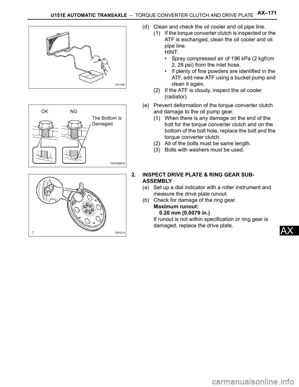
(d) Clean and check the oil cooler and oil pipe line.
(1) If the torque converter clutch is inspected or the
ATF is exchanged, clean the oil cooler and oil
pipe line.
HINT:
• Spray compressed air of 196 kPa (2 kgf/cm
2, 28 psi) from the inlet hose.
• If plenty of fine powders are identified in the
ATF, add new ATF using a bucket pump and
clean it again.
(2) If the ATF is cloudy, inspect the oil cooler
(radiator).
(e) Prevent deformation of the torque converter clutch
and damage to the oil pump gear.
(1) When there is any damage on the end of the
bolt for the torque converter clutch and on the
bottom of the bolt hole, replace the bolt and the
torque converter clutch.
(2) All of the bolts must be same length.
(3) Bolts with washers must be used.
2. INSPECT DRIVE PLATE & RING GEAR SUB-
ASSEMBLY
(a) Set up a dial indicator with a roller instrument and
measure the drive plate runout.
(b) Check for damage of the ring gear.
Maximum runout:
0.20 mm (0.0079 in.)
If runout is not within specification or ring gear is
damaged, replace the drive plate.
C011090
D025368E08
C081014
Page 1920 of 3000
U151F AUTOMATIC TRANSAXLE – TORQUE CONVERTER CLUTCH AND DRIVE PLATEAX–173
AX
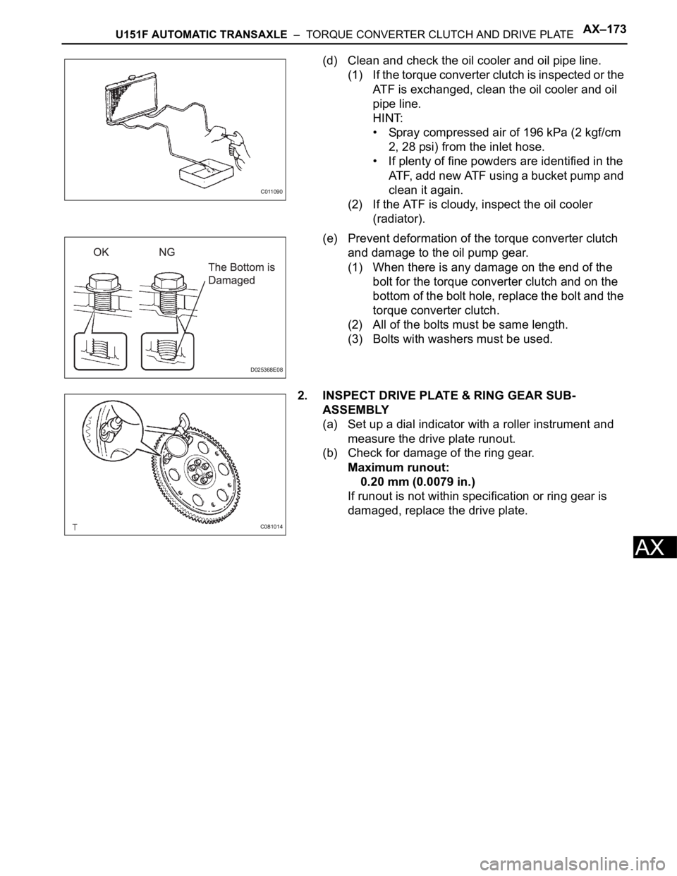
(d) Clean and check the oil cooler and oil pipe line.
(1) If the torque converter clutch is inspected or the
ATF is exchanged, clean the oil cooler and oil
pipe line.
HINT:
• Spray compressed air of 196 kPa (2 kgf/cm
2, 28 psi) from the inlet hose.
• If plenty of fine powders are identified in the
ATF, add new ATF using a bucket pump and
clean it again.
(2) If the ATF is cloudy, inspect the oil cooler
(radiator).
(e) Prevent deformation of the torque converter clutch
and damage to the oil pump gear.
(1) When there is any damage on the end of the
bolt for the torque converter clutch and on the
bottom of the bolt hole, replace the bolt and the
torque converter clutch.
(2) All of the bolts must be same length.
(3) Bolts with washers must be used.
2. INSPECT DRIVE PLATE & RING GEAR SUB-
ASSEMBLY
(a) Set up a dial indicator with a roller instrument and
measure the drive plate runout.
(b) Check for damage of the ring gear.
Maximum runout:
0.20 mm (0.0079 in.)
If runout is not within specification or ring gear is
damaged, replace the drive plate.
C011090
D025368E08
C081014