2007 TOYOTA SIENNA oil change
[x] Cancel search: oil changePage 2124 of 3000
DF–26DIFFERENTIAL – REAR DIFFERENTIAL CARRIER
DF
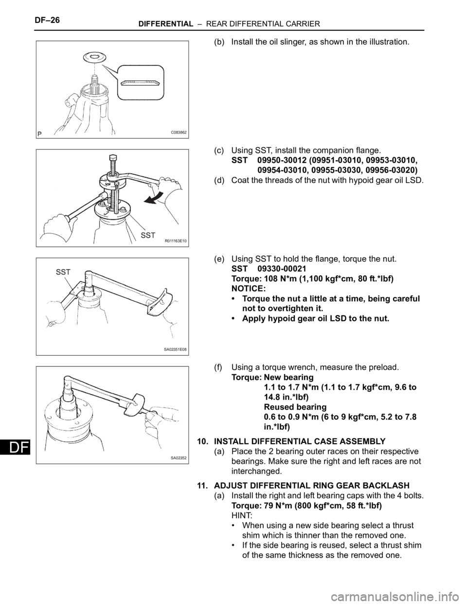
(b) Install the oil slinger, as shown in the illustration.
(c) Using SST, install the companion flange.
SST 09950-30012 (09951-03010, 09953-03010,
09954-03010, 09955-03030, 09956-03020)
(d) Coat the threads of the nut with hypoid gear oil LSD.
(e) Using SST to hold the flange, torque the nut.
SST 09330-00021
Torque: 108 N*m (1,100 kgf*cm, 80 ft.*lbf)
NOTICE:
• Torque the nut a little at a time, being careful
not to overtighten it.
• Apply hypoid gear oil LSD to the nut.
(f) Using a torque wrench, measure the preload.
Torque: New bearing
1.1 to 1.7 N*m (1.1 to 1.7 kgf*cm, 9.6 to
14.8 in.*lbf)
Reused bearing
0.6 to 0.9 N*m (6 to 9 kgf*cm, 5.2 to 7.8
in.*lbf)
10. INSTALL DIFFERENTIAL CASE ASSEMBLY
(a) Place the 2 bearing outer races on their respective
bearings. Make sure the right and left races are not
interchanged.
11. ADJUST DIFFERENTIAL RING GEAR BACKLASH
(a) Install the right and left bearing caps with the 4 bolts.
Torque: 79 N*m (800 kgf*cm, 58 ft.*lbf)
HINT:
• When using a new side bearing select a thrust
shim which is thinner than the removed one.
• If the side bearing is reused, select a thrust shim
of the same thickness as the removed one.
C083862
R 0 111 6 3 E 1 0
SA02351E08
SA02352
Page 2148 of 3000
DF–26DIFFERENTIAL – REAR DIFFERENTIAL CARRIER
DF
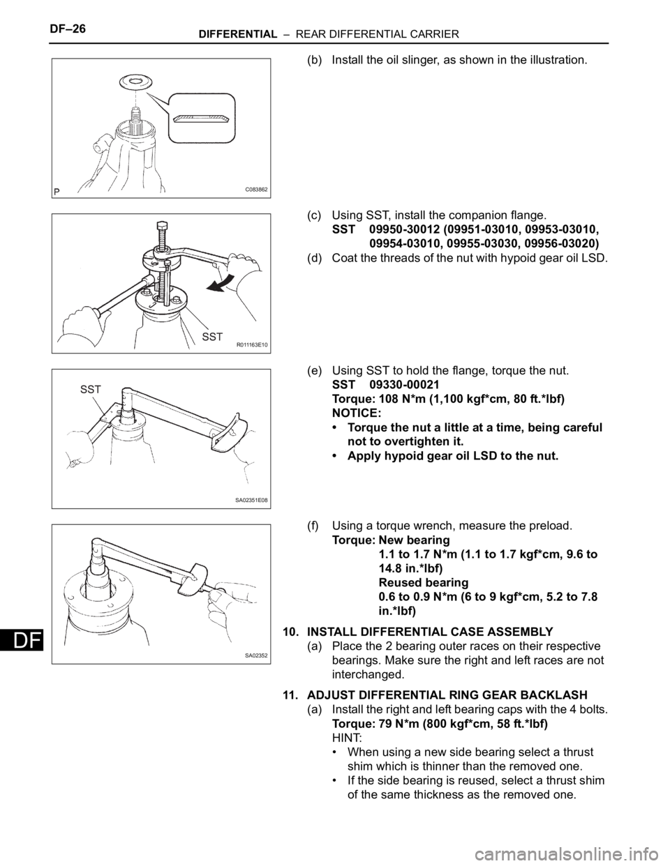
(b) Install the oil slinger, as shown in the illustration.
(c) Using SST, install the companion flange.
SST 09950-30012 (09951-03010, 09953-03010,
09954-03010, 09955-03030, 09956-03020)
(d) Coat the threads of the nut with hypoid gear oil LSD.
(e) Using SST to hold the flange, torque the nut.
SST 09330-00021
Torque: 108 N*m (1,100 kgf*cm, 80 ft.*lbf)
NOTICE:
• Torque the nut a little at a time, being careful
not to overtighten it.
• Apply hypoid gear oil LSD to the nut.
(f) Using a torque wrench, measure the preload.
Torque: New bearing
1.1 to 1.7 N*m (1.1 to 1.7 kgf*cm, 9.6 to
14.8 in.*lbf)
Reused bearing
0.6 to 0.9 N*m (6 to 9 kgf*cm, 5.2 to 7.8
in.*lbf)
10. INSTALL DIFFERENTIAL CASE ASSEMBLY
(a) Place the 2 bearing outer races on their respective
bearings. Make sure the right and left races are not
interchanged.
11. ADJUST DIFFERENTIAL RING GEAR BACKLASH
(a) Install the right and left bearing caps with the 4 bolts.
Torque: 79 N*m (800 kgf*cm, 58 ft.*lbf)
HINT:
• When using a new side bearing select a thrust
shim which is thinner than the removed one.
• If the side bearing is reused, select a thrust shim
of the same thickness as the removed one.
C083862
R 0 111 6 3 E 1 0
SA02351E08
SA02352
Page 2701 of 3000
POWER STEERING – RACK AND PINION POWER STEERING GEARPS–33
PS
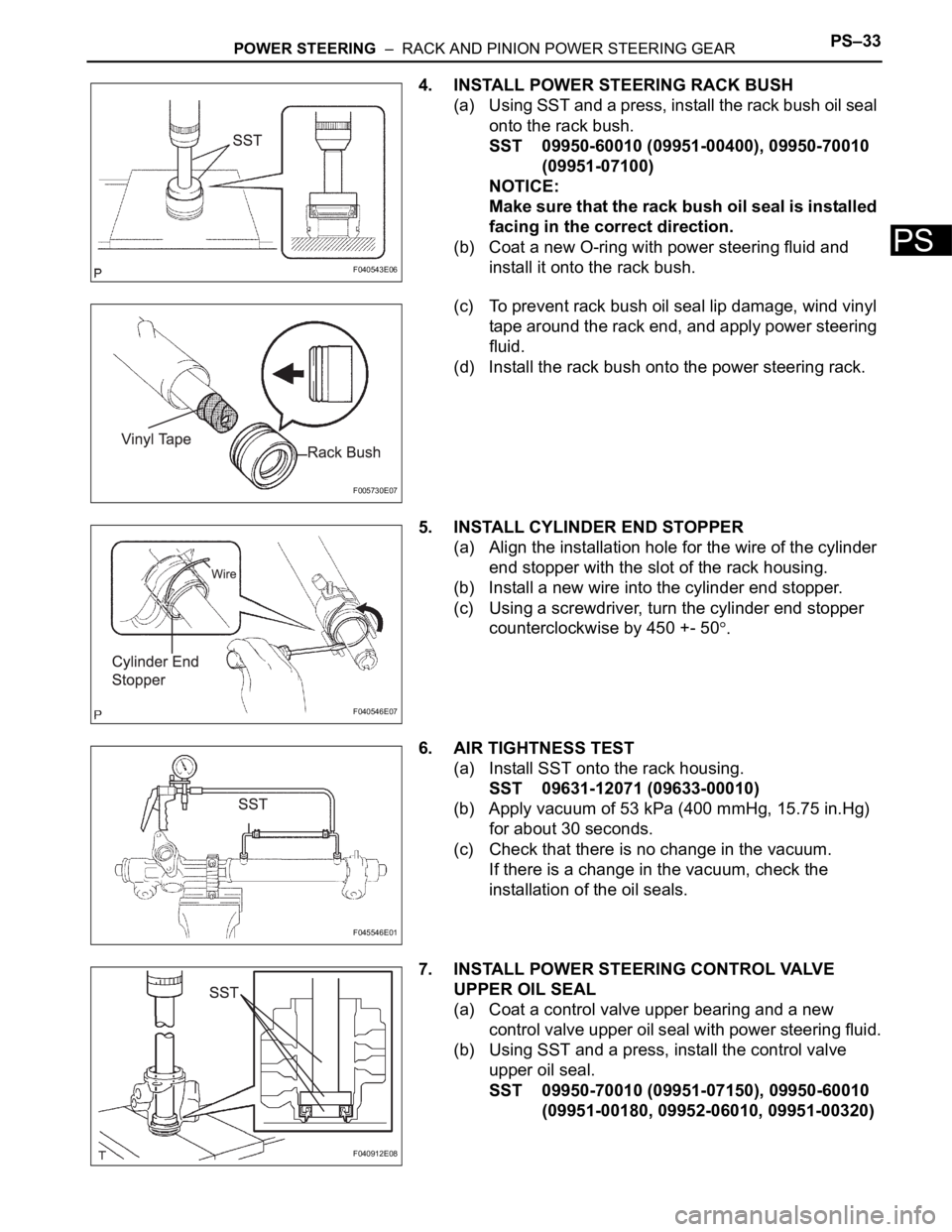
4. INSTALL POWER STEERING RACK BUSH
(a) Using SST and a press, install the rack bush oil seal
onto the rack bush.
SST 09950-60010 (09951-00400), 09950-70010
(09951-07100)
NOTICE:
Make sure that the rack bush oil seal is installed
facing in the correct direction.
(b) Coat a new O-ring with power steering fluid and
install it onto the rack bush.
(c) To prevent rack bush oil seal lip damage, wind vinyl
tape around the rack end, and apply power steering
fluid.
(d) Install the rack bush onto the power steering rack.
5. INSTALL CYLINDER END STOPPER
(a) Align the installation hole for the wire of the cylinder
end stopper with the slot of the rack housing.
(b) Install a new wire into the cylinder end stopper.
(c) Using a screwdriver, turn the cylinder end stopper
counterclockwise by 450 +- 50
.
6. AIR TIGHTNESS TEST
(a) Install SST onto the rack housing.
SST 09631-12071 (09633-00010)
(b) Apply vacuum of 53 kPa (400 mmHg, 15.75 in.Hg)
for about 30 seconds.
(c) Check that there is no change in the vacuum.
If there is a change in the vacuum, check the
installation of the oil seals.
7. INSTALL POWER STEERING CONTROL VALVE
UPPER OIL SEAL
(a) Coat a control valve upper bearing and a new
control valve upper oil seal with power steering fluid.
(b) Using SST and a press, install the control valve
upper oil seal.
SST 09950-70010 (09951-07150), 09950-60010
(09951-00180, 09952-06010, 09951-00320)
F040543E06
F005730E07
F040546E07
F045546E01
F040912E08
Page 2744 of 3000
POWER STEERING – RACK AND PINION POWER STEERING GEARPS–33
PS
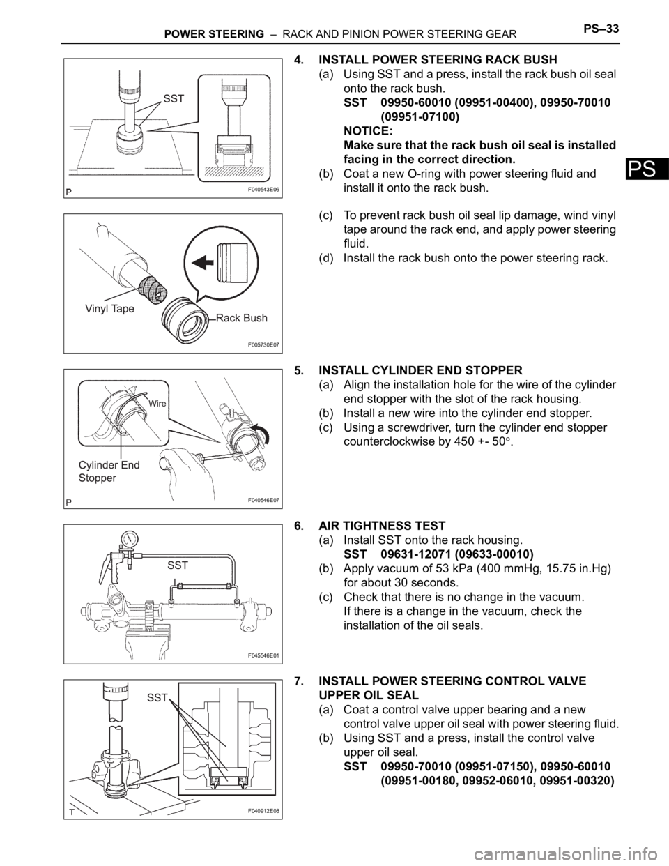
4. INSTALL POWER STEERING RACK BUSH
(a) Using SST and a press, install the rack bush oil seal
onto the rack bush.
SST 09950-60010 (09951-00400), 09950-70010
(09951-07100)
NOTICE:
Make sure that the rack bush oil seal is installed
facing in the correct direction.
(b) Coat a new O-ring with power steering fluid and
install it onto the rack bush.
(c) To prevent rack bush oil seal lip damage, wind vinyl
tape around the rack end, and apply power steering
fluid.
(d) Install the rack bush onto the power steering rack.
5. INSTALL CYLINDER END STOPPER
(a) Align the installation hole for the wire of the cylinder
end stopper with the slot of the rack housing.
(b) Install a new wire into the cylinder end stopper.
(c) Using a screwdriver, turn the cylinder end stopper
counterclockwise by 450 +- 50
.
6. AIR TIGHTNESS TEST
(a) Install SST onto the rack housing.
SST 09631-12071 (09633-00010)
(b) Apply vacuum of 53 kPa (400 mmHg, 15.75 in.Hg)
for about 30 seconds.
(c) Check that there is no change in the vacuum.
If there is a change in the vacuum, check the
installation of the oil seals.
7. INSTALL POWER STEERING CONTROL VALVE
UPPER OIL SEAL
(a) Coat a control valve upper bearing and a new
control valve upper oil seal with power steering fluid.
(b) Using SST and a press, install the control valve
upper oil seal.
SST 09950-70010 (09951-07150), 09950-60010
(09951-00180, 09952-06010, 09951-00320)
F040543E06
F005730E07
F040546E07
F045546E01
F040912E08
Page 2956 of 3000
AC–230AIR CONDITIONING – COMPRESSOR AND MAGNETIC CLUTCH
AC
2. INSPECT COMPRESSOR OIL
(a) When replacing the compressor and magnetic
clutch with a new one, after gradually removing the
refrigerant gas from the service valve, drain the
following amount of oil from the new compressor
and magnetic clutch before installation.
Standard:
(Oil capacity inside new compressor and
magnetic clutch:
225 + 15 cc (7.6 + 0.5 fl.oz.)) - (Remaining oil
amount in the removed compressor and
magnetic clutch) = (Oil amount to be
removed when replacing)
NOTICE:
• When checking the compressor oil level,
observe the precautions on the cooler
removal / installation.
• Because compressor oil remains in the pipes
of the vehicle, if a new compressor and
magnetic clutch is installed without removing
some oil inside, the oil amount becomes
excessive, preventing heat exchange in the
refrigerant cycle and causing refrigerant
failure.
• If the remaining oil in the removed
compressor and magnetic clutch is too small
in volume, check for oil leakage.
• Be sure to use ND-OIL 8 for compressor oil.
3. INSPECT COMPRESSOR AND MAGNETIC CLUTCH
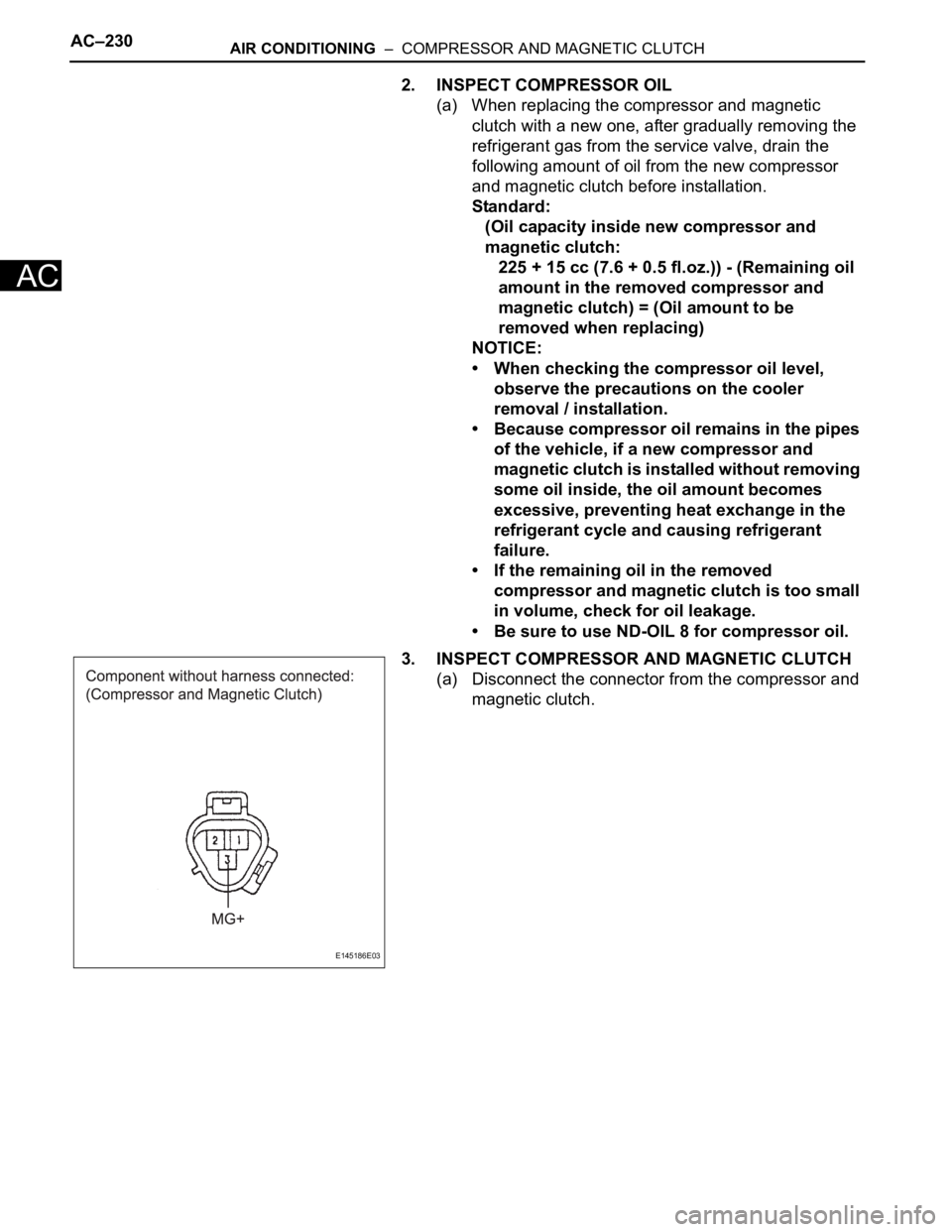
(a) Disconnect the connector from the compressor and
magnetic clutch.
E145186E03
Page 2958 of 3000
AC–232AIR CONDITIONING – COMPRESSOR AND MAGNETIC CLUTCH
AC
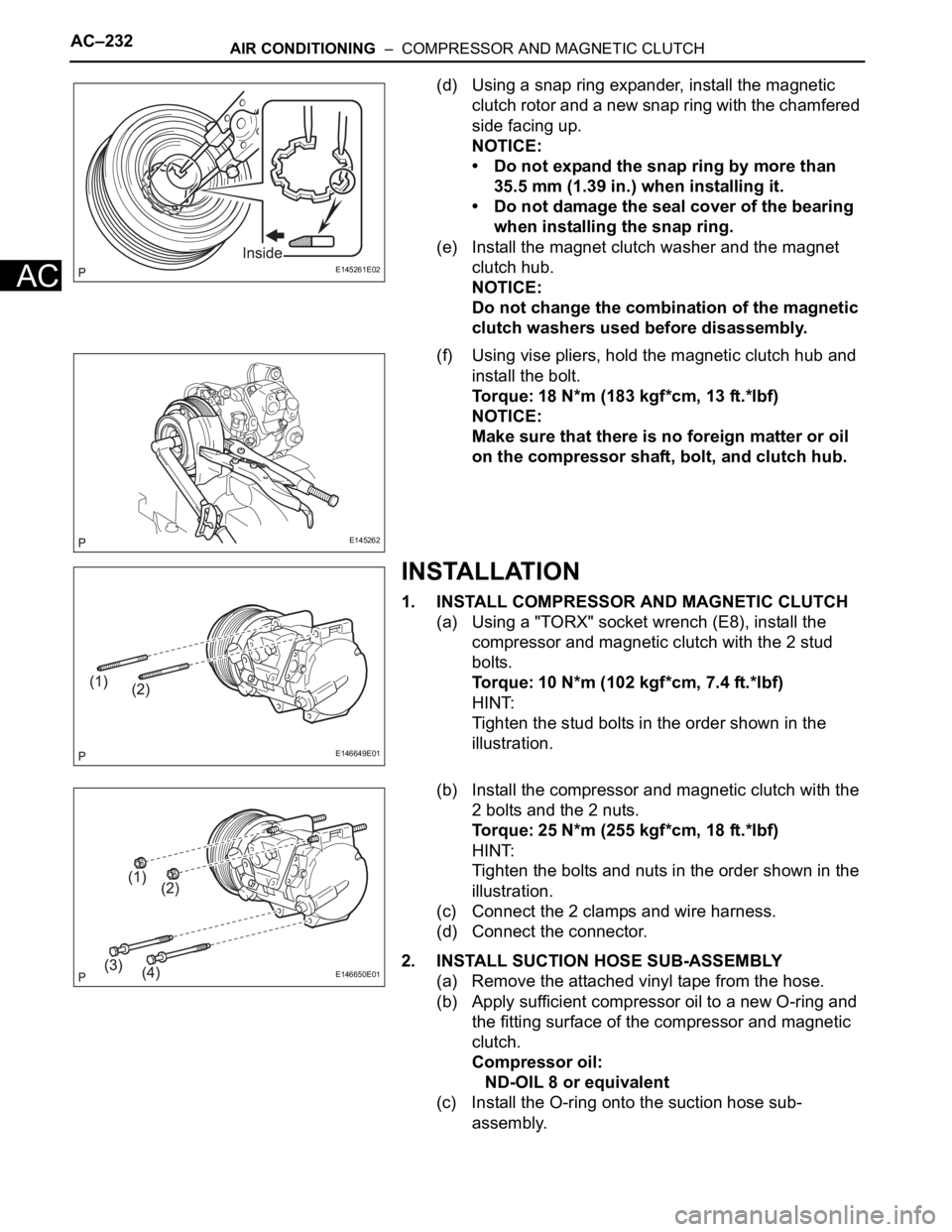
(d) Using a snap ring expander, install the magnetic
clutch rotor and a new snap ring with the chamfered
side facing up.
NOTICE:
• Do not expand the snap ring by more than
35.5 mm (1.39 in.) when installing it.
• Do not damage the seal cover of the bearing
when installing the snap ring.
(e) Install the magnet clutch washer and the magnet
clutch hub.
NOTICE:
Do not change the combination of the magnetic
clutch washers used before disassembly.
(f) Using vise pliers, hold the magnetic clutch hub and
install the bolt.
Torque: 18 N*m (183 kgf*cm, 13 ft.*lbf)
NOTICE:
Make sure that there is no foreign matter or oil
on the compressor shaft, bolt, and clutch hub.
INSTALLATION
1. INSTALL COMPRESSOR AND MAGNETIC CLUTCH
(a) Using a "TORX" socket wrench (E8), install the
compressor and magnetic clutch with the 2 stud
bolts.
Torque: 10 N*m (102 kgf*cm, 7.4 ft.*lbf)
HINT:
Tighten the stud bolts in the order shown in the
illustration.
(b) Install the compressor and magnetic clutch with the
2 bolts and the 2 nuts.
Torque: 25 N*m (255 kgf*cm, 18 ft.*lbf)
HINT:
Tighten the bolts and nuts in the order shown in the
illustration.
(c) Connect the 2 clamps and wire harness.
(d) Connect the connector.
2. INSTALL SUCTION HOSE SUB-ASSEMBLY
(a) Remove the attached vinyl tape from the hose.
(b) Apply sufficient compressor oil to a new O-ring and
the fitting surface of the compressor and magnetic
clutch.
Compressor oil:
ND-OIL 8 or equivalent
(c) Install the O-ring onto the suction hose sub-
assembly.
E145261E02
E145262
E146649E01
E146650E01
Page 2970 of 3000
AC–230AIR CONDITIONING – COMPRESSOR AND MAGNETIC CLUTCH
AC
2. INSPECT COMPRESSOR OIL
(a) When replacing the compressor and magnetic
clutch with a new one, after gradually removing the
refrigerant gas from the service valve, drain the
following amount of oil from the new compressor
and magnetic clutch before installation.
Standard:
(Oil capacity inside new compressor and
magnetic clutch:
225 + 15 cc (7.6 + 0.5 fl.oz.)) - (Remaining oil
amount in the removed compressor and
magnetic clutch) = (Oil amount to be
removed when replacing)
NOTICE:
• When checking the compressor oil level,
observe the precautions on the cooler
removal / installation.
• Because compressor oil remains in the pipes
of the vehicle, if a new compressor and
magnetic clutch is installed without removing
some oil inside, the oil amount becomes
excessive, preventing heat exchange in the
refrigerant cycle and causing refrigerant
failure.
• If the remaining oil in the removed
compressor and magnetic clutch is too small
in volume, check for oil leakage.
• Be sure to use ND-OIL 8 for compressor oil.
3. INSPECT COMPRESSOR AND MAGNETIC CLUTCH
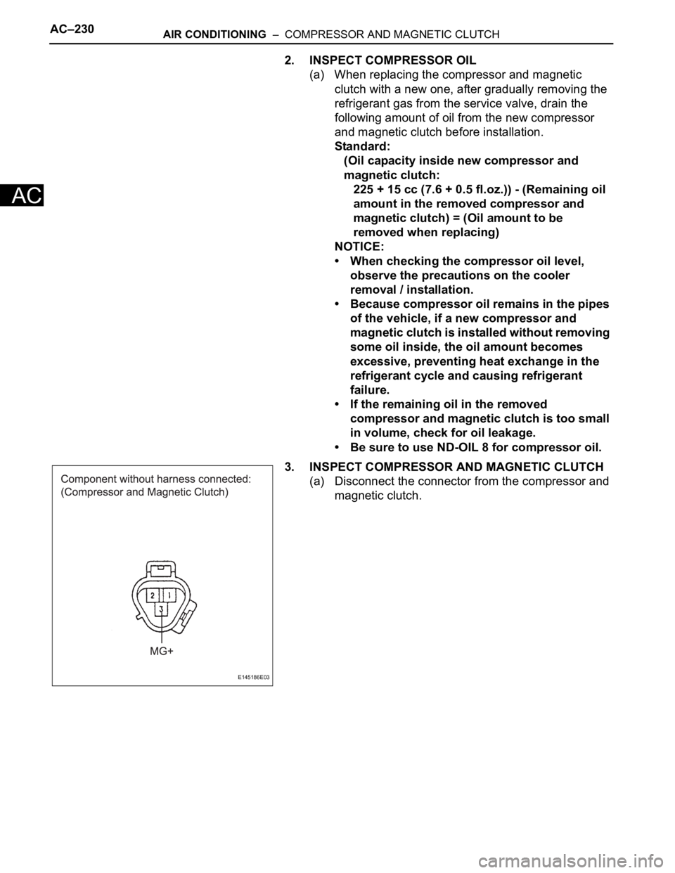
(a) Disconnect the connector from the compressor and
magnetic clutch.
E145186E03
Page 2972 of 3000

AC–232AIR CONDITIONING – COMPRESSOR AND MAGNETIC CLUTCH
AC
(d) Using a snap ring expander, install the magnetic
clutch rotor and a new snap ring with the chamfered
side facing up.
NOTICE:
• Do not expand the snap ring by more than
35.5 mm (1.39 in.) when installing it.
• Do not damage the seal cover of the bearing
when installing the snap ring.
(e) Install the magnet clutch washer and the magnet
clutch hub.
NOTICE:
Do not change the combination of the magnetic
clutch washers used before disassembly.
(f) Using vise pliers, hold the magnetic clutch hub and
install the bolt.
Torque: 18 N*m (183 kgf*cm, 13 ft.*lbf)
NOTICE:
Make sure that there is no foreign matter or oil
on the compressor shaft, bolt, and clutch hub.
INSTALLATION
1. INSTALL COMPRESSOR AND MAGNETIC CLUTCH
(a) Using a "TORX" socket wrench (E8), install the
compressor and magnetic clutch with the 2 stud
bolts.
Torque: 10 N*m (102 kgf*cm, 7.4 ft.*lbf)
HINT:
Tighten the stud bolts in the order shown in the
illustration.
(b) Install the compressor and magnetic clutch with the
2 bolts and the 2 nuts.
Torque: 25 N*m (255 kgf*cm, 18 ft.*lbf)
HINT:
Tighten the bolts and nuts in the order shown in the
illustration.
(c) Connect the 2 clamps and wire harness.
(d) Connect the connector.
2. INSTALL SUCTION HOSE SUB-ASSEMBLY
(a) Remove the attached vinyl tape from the hose.
(b) Apply sufficient compressor oil to a new O-ring and
the fitting surface of the compressor and magnetic
clutch.
Compressor oil:
ND-OIL 8 or equivalent
(c) Install the O-ring onto the suction hose sub-
assembly.
E145261E02
E145262
E146649E01
E146650E01