2007 TOYOTA SIENNA checking oil
[x] Cancel search: checking oilPage 80 of 3000

IG–62GR-FE IGNITION – IGNITION COIL AND SPARK PLUG
IG
ON-VEHICLE INSPECTION
NOTICE:
In this section, the terms "cold" and "hot" refer to the
temperature of the coils. "Cold" means approximately -
10
C (14F) to 50C (122F). "Hot" means approximately
50
C (122F) to 100C (212F).
1. INSPECT IGNITION COIL ASSEMBLY
(a) Check for DTCs.
NOTICE:
If any DTC is present, perform troubleshooting
in accordance with the procedures for that DTC.
(b) Remove the ignition coil assembly and spark plug.
(See page IG-8).
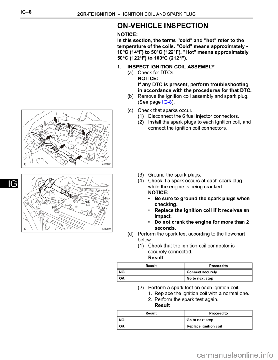
(c) Check that sparks occur.
(1) Disconnect the 6 fuel injector connectors.
(2) Install the spark plugs to each ignition coil, and
connect the ignition coil connectors.
(3) Ground the spark plugs.
(4) Check if a spark occurs at each spark plug
while the engine is being cranked.
NOTICE:
• Be sure to ground the spark plugs when
checking.
• Replace the ignition coil if it receives an
impact.
• Do not crank the engine for more than 2
seconds.
(d) Perform the spark test according to the flowchart
below.
(1) Check that the ignition coil connector is
securely connected.
Result
(2) Perform a spark test on each ignition coil.
1. Replace the ignition coil with a normal one.
2. Perform the spark test again.
Result
A133895
A133897
Result Proceed to
NG Connect securely
OK Go to next step
Result Proceed to
NG Go to next step
OK Replace ignition coil
Page 1315 of 3000
IG–62GR-FE IGNITION – IGNITION COIL AND SPARK PLUG
IG
ON-VEHICLE INSPECTION
NOTICE:
In this section, the terms "cold" and "hot" refer to the
temperature of the coils. "Cold" means approximately -
10
C (14F) to 50C (122F). "Hot" means approximately
50
C (122F) to 100C (212F).
1. INSPECT IGNITION COIL ASSEMBLY
(a) Check for DTCs.
NOTICE:
If any DTC is present, perform troubleshooting
in accordance with the procedures for that DTC.
(b) Remove the ignition coil assembly and spark plug.
(See page IG-8).
(c) Check that sparks occur.
(1) Disconnect the 6 fuel injector connectors.
(2) Install the spark plugs to each ignition coil, and
connect the ignition coil connectors.
(3) Ground the spark plugs.
(4) Check if a spark occurs at each spark plug
while the engine is being cranked.
NOTICE:
• Be sure to ground the spark plugs when
checking.
• Replace the ignition coil if it receives an
impact.
• Do not crank the engine for more than 2
seconds.
(d) Perform the spark test according to the flowchart
below.
(1) Check that the ignition coil connector is
securely connected.
Result
(2) Perform a spark test on each ignition coil.
1. Replace the ignition coil with a normal one.
2. Perform the spark test again.
Result
A133895
A133897
Result Proceed to
NG Connect securely
OK Go to next step
Result Proceed to
NG Go to next step
OK Replace ignition coil
Page 2378 of 3000
BC–30BRAKE CONTROL – ANTI-LOCK BRAKE SYSTEM
BC
OK
(a) Clear the DTCs (See page BC-10).
(b) Drive the vehicle at a speed of approximately 32 km/h
(20 mph) or more for 60 seconds or more.
(c) Check that the same DTCs are recorded (See page BC-
10).
HINT:
Reinstall the sensors, connectors, etc. and restore the
vehicle to its prior condition before rechecking for DTCs.
Result
B
C
A
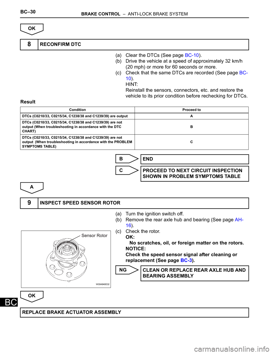
(a) Turn the ignition switch off.
(b) Remove the rear axle hub and bearing (See page AH-
16).
(c) Check the rotor.
OK:
No scratches, oil, or foreign matter on the rotors.
NOTICE:
Check the speed sensor signal after cleaning or
replacement (See page BC-3).
NG
OK
8RECONFIRM DTC
Condition Proceed to
DTCs (C0210/33, C0215/34, C1238/38 and C1239/39) are output A
DTCs (C0210/33, C0215/34, C1238/38 and C1239/39) are not
output (When troubleshooting in accordance with the DTC
CHART)B
DTCs (C0210/33, C0215/34, C1238/38 and C1239/39) are not
output (When troubleshooting in accordance with the PROBLEM
SYMPTOMS TABLE)C
END
PROCEED TO NEXT CIRCUIT INSPECTION
SHOWN IN PROBLEM SYMPTOMS TABLE
9INSPECT SPEED SENSOR ROTOR
W004846E02
CLEAN OR REPLACE REAR AXLE HUB AND
BEARING ASSEMBLY
REPLACE BRAKE ACTUATOR ASSEMBLY
Page 2391 of 3000
BC–24BRAKE CONTROL – ANTI-LOCK BRAKE SYSTEM
BC
OK
(a) Clear the DTCs (See page BC-10).
(b) Drive the vehicle at a speed of approximately 32 km/h
(20 mph) or more for 60 seconds or more.
(c) Check that the same DTCs are recorded (See page BC-
10).
HINT:
Reinstall the sensors, connectors, etc. and restore the
vehicle to its prior condition before rechecking for DTCs.
Result
B
C
A
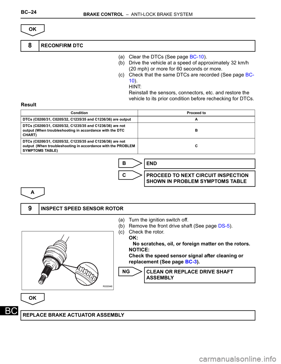
(a) Turn the ignition switch off.
(b) Remove the front drive shaft (See page DS-5).
(c) Check the rotor.
OK:
No scratches, oil, or foreign matter on the rotors.
NOTICE:
Check the speed sensor signal after cleaning or
replacement (See page BC-3).
NG
OK
8RECONFIRM DTC
Condition Proceed to
DTCs (C0200/31, C0205/32, C1235/35 and C1236/36) are output A
DTCs (C0200/31, C0205/32, C1235/35 and C1236/36) are not
output (When troubleshooting in accordance with the DTC
CHART)B
DTCs (C0200/31, C0205/32, C1235/35 and C1236/36) are not
output (When troubleshooting in accordance with the PROBLEM
SYMPTOMS TABLE)C
END
PROCEED TO NEXT CIRCUIT INSPECTION
SHOWN IN PROBLEM SYMPTOMS TABLE
9INSPECT SPEED SENSOR ROTOR
R000948
CLEAN OR REPLACE DRIVE SHAFT
ASSEMBLY
REPLACE BRAKE ACTUATOR ASSEMBLY
Page 2553 of 3000
BC–24BRAKE CONTROL – ANTI-LOCK BRAKE SYSTEM
BC
OK
(a) Clear the DTCs (See page BC-10).
(b) Drive the vehicle at a speed of approximately 32 km/h
(20 mph) or more for 60 seconds or more.
(c) Check that the same DTCs are recorded (See page BC-
10).
HINT:
Reinstall the sensors, connectors, etc. and restore the
vehicle to its prior condition before rechecking for DTCs.
Result
B
C
A
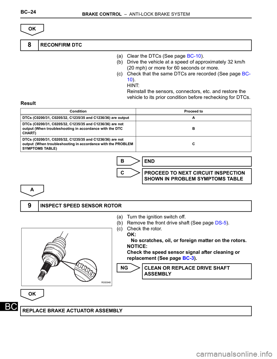
(a) Turn the ignition switch off.
(b) Remove the front drive shaft (See page DS-5).
(c) Check the rotor.
OK:
No scratches, oil, or foreign matter on the rotors.
NOTICE:
Check the speed sensor signal after cleaning or
replacement (See page BC-3).
NG
OK
8RECONFIRM DTC
Condition Proceed to
DTCs (C0200/31, C0205/32, C1235/35 and C1236/36) are output A
DTCs (C0200/31, C0205/32, C1235/35 and C1236/36) are not
output (When troubleshooting in accordance with the DTC
CHART)B
DTCs (C0200/31, C0205/32, C1235/35 and C1236/36) are not
output (When troubleshooting in accordance with the PROBLEM
SYMPTOMS TABLE)C
END
PROCEED TO NEXT CIRCUIT INSPECTION
SHOWN IN PROBLEM SYMPTOMS TABLE
9INSPECT SPEED SENSOR ROTOR
R000948
CLEAN OR REPLACE DRIVE SHAFT
ASSEMBLY
REPLACE BRAKE ACTUATOR ASSEMBLY
Page 2564 of 3000
BC–30BRAKE CONTROL – ANTI-LOCK BRAKE SYSTEM
BC
OK
(a) Clear the DTCs (See page BC-10).
(b) Drive the vehicle at a speed of approximately 32 km/h
(20 mph) or more for 60 seconds or more.
(c) Check that the same DTCs are recorded (See page BC-
10).
HINT:
Reinstall the sensors, connectors, etc. and restore the
vehicle to its prior condition before rechecking for DTCs.
Result
B
C
A
(a) Turn the ignition switch off.
(b) Remove the rear axle hub and bearing (See page AH-
16).
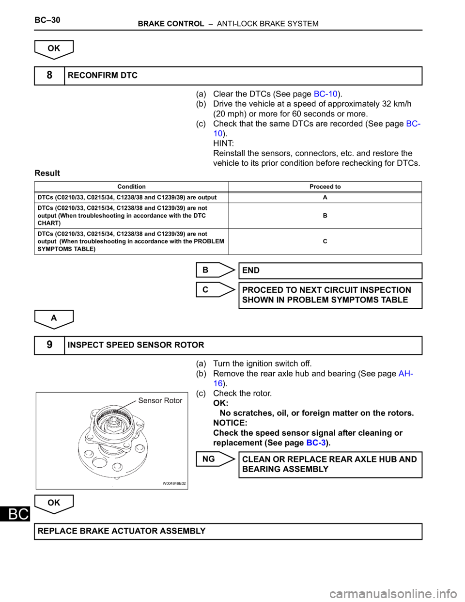
(c) Check the rotor.
OK:
No scratches, oil, or foreign matter on the rotors.
NOTICE:
Check the speed sensor signal after cleaning or
replacement (See page BC-3).
NG
OK
8RECONFIRM DTC
Condition Proceed to
DTCs (C0210/33, C0215/34, C1238/38 and C1239/39) are output A
DTCs (C0210/33, C0215/34, C1238/38 and C1239/39) are not
output (When troubleshooting in accordance with the DTC
CHART)B
DTCs (C0210/33, C0215/34, C1238/38 and C1239/39) are not
output (When troubleshooting in accordance with the PROBLEM
SYMPTOMS TABLE)C
END
PROCEED TO NEXT CIRCUIT INSPECTION
SHOWN IN PROBLEM SYMPTOMS TABLE
9INSPECT SPEED SENSOR ROTOR
W004846E02
CLEAN OR REPLACE REAR AXLE HUB AND
BEARING ASSEMBLY
REPLACE BRAKE ACTUATOR ASSEMBLY
Page 2956 of 3000
AC–230AIR CONDITIONING – COMPRESSOR AND MAGNETIC CLUTCH
AC
2. INSPECT COMPRESSOR OIL
(a) When replacing the compressor and magnetic
clutch with a new one, after gradually removing the
refrigerant gas from the service valve, drain the
following amount of oil from the new compressor
and magnetic clutch before installation.
Standard:
(Oil capacity inside new compressor and
magnetic clutch:
225 + 15 cc (7.6 + 0.5 fl.oz.)) - (Remaining oil
amount in the removed compressor and
magnetic clutch) = (Oil amount to be
removed when replacing)
NOTICE:
• When checking the compressor oil level,
observe the precautions on the cooler
removal / installation.
• Because compressor oil remains in the pipes
of the vehicle, if a new compressor and
magnetic clutch is installed without removing
some oil inside, the oil amount becomes
excessive, preventing heat exchange in the
refrigerant cycle and causing refrigerant
failure.
• If the remaining oil in the removed
compressor and magnetic clutch is too small
in volume, check for oil leakage.
• Be sure to use ND-OIL 8 for compressor oil.
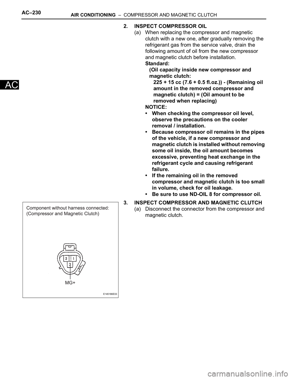
3. INSPECT COMPRESSOR AND MAGNETIC CLUTCH
(a) Disconnect the connector from the compressor and
magnetic clutch.
E145186E03
Page 2970 of 3000
AC–230AIR CONDITIONING – COMPRESSOR AND MAGNETIC CLUTCH
AC
2. INSPECT COMPRESSOR OIL
(a) When replacing the compressor and magnetic
clutch with a new one, after gradually removing the
refrigerant gas from the service valve, drain the
following amount of oil from the new compressor
and magnetic clutch before installation.
Standard:
(Oil capacity inside new compressor and
magnetic clutch:
225 + 15 cc (7.6 + 0.5 fl.oz.)) - (Remaining oil
amount in the removed compressor and
magnetic clutch) = (Oil amount to be
removed when replacing)
NOTICE:
• When checking the compressor oil level,
observe the precautions on the cooler
removal / installation.
• Because compressor oil remains in the pipes
of the vehicle, if a new compressor and
magnetic clutch is installed without removing
some oil inside, the oil amount becomes
excessive, preventing heat exchange in the
refrigerant cycle and causing refrigerant
failure.
• If the remaining oil in the removed
compressor and magnetic clutch is too small
in volume, check for oil leakage.
• Be sure to use ND-OIL 8 for compressor oil.
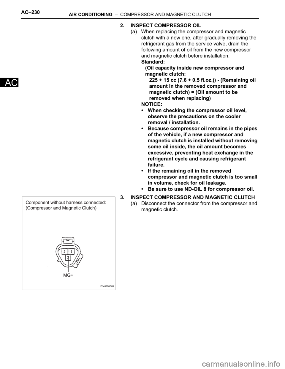
3. INSPECT COMPRESSOR AND MAGNETIC CLUTCH
(a) Disconnect the connector from the compressor and
magnetic clutch.
E145186E03