2007 TOYOTA SIENNA low oil pressure
[x] Cancel search: low oil pressurePage 196 of 3000
PS–14POWER STEERING – VANE PUMP
PS
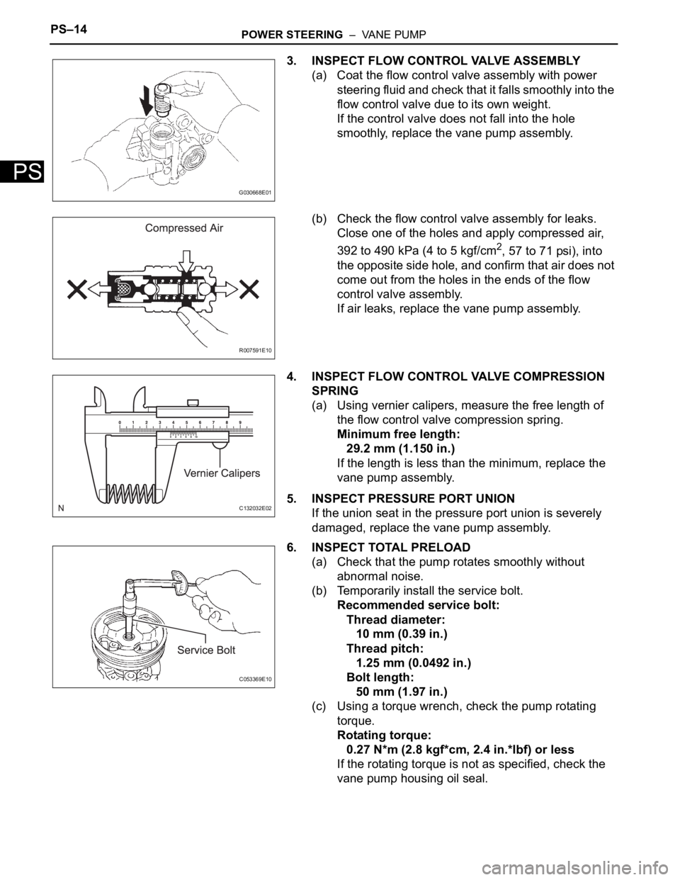
3. INSPECT FLOW CONTROL VALVE ASSEMBLY
(a) Coat the flow control valve assembly with power
steering fluid and check that it falls smoothly into the
flow control valve due to its own weight.
If the control valve does not fall into the hole
smoothly, replace the vane pump assembly.
(b) Check the flow control valve assembly for leaks.
Close one of the holes and apply compressed air,
392 to 490 kPa (4 to 5 kgf/cm
2, 57 to 71 psi), into
the opposite side hole, and confirm that air does not
come out from the holes in the ends of the flow
control valve assembly.
If air leaks, replace the vane pump assembly.
4. INSPECT FLOW CONTROL VALVE COMPRESSION
SPRING
(a) Using vernier calipers, measure the free length of
the flow control valve compression spring.
Minimum free length:
29.2 mm (1.150 in.)
If the length is less than the minimum, replace the
vane pump assembly.
5. INSPECT PRESSURE PORT UNION
If the union seat in the pressure port union is severely
damaged, replace the vane pump assembly.
6. INSPECT TOTAL PRELOAD
(a) Check that the pump rotates smoothly without
abnormal noise.
(b) Temporarily install the service bolt.
Recommended service bolt:
Thread diameter:
10 mm (0.39 in.)
Thread pitch:
1.25 mm (0.0492 in.)
Bolt length:
50 mm (1.97 in.)
(c) Using a torque wrench, check the pump rotating
torque.
Rotating torque:
0.27 N*m (2.8 kgf*cm, 2.4 in.*lbf) or less
If the rotating torque is not as specified, check the
vane pump housing oil seal.
G030668E01
R007591E10
C132032E02
C053369E10
Page 394 of 3000
ES–882GR-FE ENGINE CONTROL SYSTEM – SFI SYSTEM
ES
HINT:
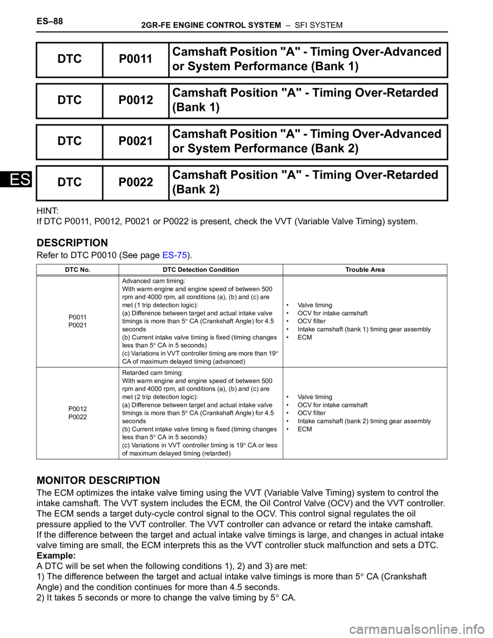
If DTC P0011, P0012, P0021 or P0022 is present, check the VVT (Variable Valve Timing) system.
DESCRIPTION
Refer to DTC P0010 (See page ES-75).
MONITOR DESCRIPTION
The ECM optimizes the intake valve timing using the VVT (Variable Valve Timing) system to control the
intake camshaft. The VVT system includes the ECM, the Oil Control Valve (OCV) and the VVT controller.
The ECM sends a target duty-cycle control signal to the OCV. This control signal regulates the oil
pressure applied to the VVT controller. The VVT controller can advance or retard the intake camshaft.
If the difference between the target and actual intake valve timings is large, and changes in actual intake
valve timing are small, the ECM interprets this as the VVT controller stuck malfunction and sets a DTC.
Example:
A DTC will be set when the following conditions 1), 2) and 3) are met:
1) The difference between the target and actual intake valve timings is more than 5
CA (Crankshaft
Angle) and the condition continues for more than 4.5 seconds.
2) It takes 5 seconds or more to change the valve timing by 5
CA.
DTC P0011Camshaft Position "A" - Timing Over-Advanced
or System Performance (Bank 1)
DTC P0012Camshaft Position "A" - Timing Over-Retarded
(Bank 1)
DTC P0021Camshaft Position "A" - Timing Over-Advanced
or System Performance (Bank 2)
DTC P0022Camshaft Position "A" - Timing Over-Retarded
(Bank 2)
DTC No. DTC Detection Condition Trouble Area
P0011
P0021Advanced cam timing:
With warm engine and engine speed of between 500
rpm and 4000 rpm, all conditions (a), (b) and (c) are
met (1 trip detection logic):
(a) Difference between target and actual intake valve
timings is more than 5
CA (Crankshaft Angle) for 4.5
seconds
(b) Current intake valve timing is fixed (timing changes
less than 5
CA in 5 seconds)
(c) Variations in VVT controller timing are more than 19
CA of maximum delayed timing (advanced)• Valve timing
• OCV for intake camshaft
• OCV filter
• Intake camshaft (bank 1) timing gear assembly
•ECM
P0012
P0022Retarded cam timing:
With warm engine and engine speed of between 500
rpm and 4000 rpm, all conditions (a), (b) and (c) are
met (2 trip detection logic):
(a) Difference between target and actual intake valve
timings is more than 5
CA (Crankshaft Angle) for 4.5
seconds
(b) Current intake valve timing is fixed (timing changes
less than 5
CA in 5 seconds)
(c) Variations in VVT controller timing is 19
CA or less
of maximum delayed timing (retarded)• Valve timing
• OCV for intake camshaft
• OCV filter
• Intake camshaft (bank 2) timing gear assembly
•ECM
Page 402 of 3000

ES–962GR-FE ENGINE CONTROL SYSTEM – SFI SYSTEM
ES
MONITOR DESCRIPTION
The ECM optimizes the valve timing using the VVT system to control the exhaust camshaft. The VVT
system includes the ECM, the OCV and the VVT controller. The ECM sends a target duty-cycle control
signal to the OCV. This control signal regulates the oil pressure supplied to the VVT controller. The VVT
controller can advance or retard the exhaust camshaft.
After the ECM sends the target duty-cycle signal to the OCV, the ECM monitors the OCV current to
establish an actual duty-cycle. The ECM determines the existence of a malfunction and sets the DTC
when the actual duty-cycle ratio varies from the target duty-cycle ratio.
MONITOR STRATEGY
TYPICAL ENABLING CONDITIONS
TYPICAL MALFUNCTION THRESHOLDS
COMPONENT OPERATING RANGE
Related DTCsP0013: VVT OCV (bank 1) open/short
P0023: VVT OCV (bank 2) open/short
Required sensors / components (Main) VVT OCV (Variable Valve Timing oil control valve)
Required sensors / components (Sub) -
Frequency of operation Continuous
Duration 1 second
MIL operation Immediate
Sequence of operation None
Monitor runs whenever following DTCs are not present None
All of the following conditions are met: -
Starter OFF
Engine switch ON
Time after engine switch off to on 0.5 seconds or more
One of the following conditions is met: Condition A, B or C
A. All of the following conditions are met: -
Battery voltage 11 to 13 V
Target duty ratio Less than 70%
B. All of the following conditions are met: -
Battery voltage 13 V or more
Target duty ratio Less than 80%
C. All of the following conditions are met: -
Current cut status Not cut
VVT duty ratio More than 3 %, and less than 100 %
Page 412 of 3000
ES–1062GR-FE ENGINE CONTROL SYSTEM – SFI SYSTEM
ES
DESCRIPTION
Refer to DTC P0335 (See page ES-220).
MONITOR DESCRIPTION
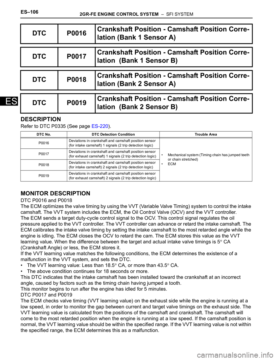
DTC P0016 and P0018
The ECM optimizes the valve timing by using the VVT (Variable Valve Timing) system to control the intake
camshaft. The VVT system includes the ECM, the Oil Control Valve (OCV) and the VVT controller.
The ECM sends a target duty-cycle control signal to the OCV. This control signal regulates the oil
pressure applied to the VVT controller. The VVT controller can advance or retard the intake camshaft. The
ECM calibrates the intake valve timing by setting the intake camshaft to the most retarded angle while the
engine is idling. The ECM closes the OCV to retard the cam. The ECM stores this value as the VVT
learning value. When the difference between the target and actual intake valve timings is 5
CA
(Crankshaft Angle) or less, the ECM stores it.
If the VVT learning value matches the following conditions, the ECM determines the existence of a
malfunction in the VVT system, and sets the DTC.
• The VVT learning value: Less than 18.5
CA, or more than 43.5 CA.
• The above condition continues for 18 seconds or more.
This DTC indicates that the intake camshaft has been installed toward the crankshaft at an incorrect
angle, caused by factors such as the timing chain having jumped a tooth.
This monitor begins to run after the engine has idled for 5 minutes.
DTC P0017 and P0019
The ECM checks valve timing (VVT learning value) on the exhaust side while the engine is running at a
low speed, in order to monitor the gap between current and target valve timings on the exhaust side. The
VVT learning value is calculated from the positions of the camshaft and crankshaft. The camshaft will
come to the most retarded position when the engine is running at a low speed. If the camshaft position is
normal, the VVT learning value should be within the specified range. If the VVT learning value is not within
the specified range, the ECM determines this as a malfunction.
DTC P0016Crankshaft Position - Camshaft Position Corre-
lation (Bank 1 Sensor A)
DTC P0017Crankshaft Position - Camshaft Position Corre-
lation (Bank 1 Sensor B)
DTC P0018Crankshaft Position - Camshaft Position Corre-
lation (Bank 2 Sensor A)
DTC P0019Crankshaft Position - Camshaft Position Corre-
lation (Bank 2 Sensor B)
DTC No. DTC Detection Condition Trouble Area
P0016Deviations in crankshaft and camshaft position sensor
(for intake camshaft) 1 signals (2 trip detection logic)
• Mechanical system (Timing chain has jumped teeth
or chain stretched)
•ECM P0017Deviations in crankshaft and camshaft position sensor
(for exhaust camshaft) 1 signals (2 trip detection logic)
P0018Deviations in crankshaft and camshaft position sensor
(for intake camshaft) 2 signals (2 trip detection logic)
P0019Deviations in crankshaft and camshaft position sensor
(for exhaust camshaft) 2 signals (2 trip detection logic)
Page 518 of 3000
ES–2122GR-FE ENGINE CONTROL SYSTEM – SFI SYSTEM
ES
(e) Crank the engine for less than 2 seconds and check the
spark.
OK:
Sparks jump across electrode gap.
(f) Install the ignition coil.
(g) Reconnect the injector connectors.
NG
OK
(a) Measure the cylinder compression pressure of the
misfiring cylinder (See page EM-3).
NG
OK
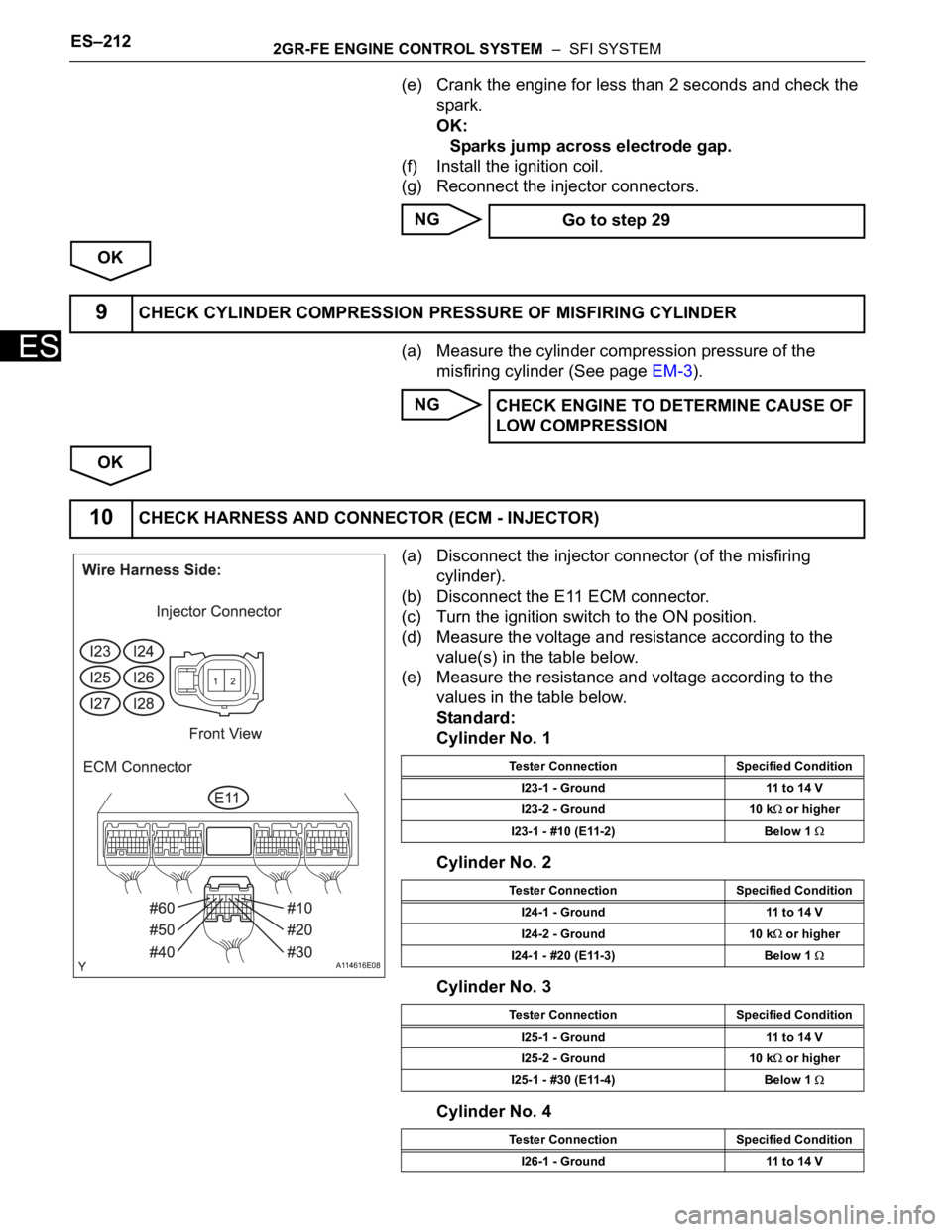
(a) Disconnect the injector connector (of the misfiring
cylinder).
(b) Disconnect the E11 ECM connector.
(c) Turn the ignition switch to the ON position.
(d) Measure the voltage and resistance according to the
value(s) in the table below.
(e) Measure the resistance and voltage according to the
values in the table below.
Standard:
Cylinder No. 1
Cylinder No. 2
Cylinder No. 3
Cylinder No. 4 Go to step 29
9CHECK CYLINDER COMPRESSION PRESSURE OF MISFIRING CYLINDER
CHECK ENGINE TO DETERMINE CAUSE OF
LOW COMPRESSION
10CHECK HARNESS AND CONNECTOR (ECM - INJECTOR)
A114616E08
Tester Connection Specified Condition
I23-1 - Ground 11 to 14 V
I23-2 - Ground 10 k
or higher
I23-1 - #10 (E11-2) Below 1
Tester Connection Specified Condition
I24-1 - Ground 11 to 14 V
I24-2 - Ground 10 k
or higher
I24-1 - #20 (E11-3) Below 1
Tester Connection Specified Condition
I25-1 - Ground 11 to 14 V
I25-2 - Ground 10 k
or higher
I25-1 - #30 (E11-4) Below 1
Tester Connection Specified Condition
I26-1 - Ground 11 to 14 V
Page 523 of 3000
2GR-FE ENGINE CONTROL SYSTEM – SFI SYSTEMES–217
ES
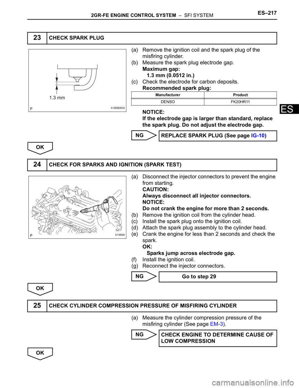
(a) Remove the ignition coil and the spark plug of the
misfiring cylinder.
(b) Measure the spark plug electrode gap.
Maximum gap:
1.3 mm (0.0512 in.)
(c) Check the electrode for carbon deposits.
Recommended spark plug:
NOTICE:
If the electrode gap is larger than standard, replace
the spark plug. Do not adjust the electrode gap.
NG
OK
(a) Disconnect the injector connectors to prevent the engine
from starting.
CAUTION:
Always disconnect all injector connectors.
NOTICE:
Do not crank the engine for more than 2 seconds.
(b) Remove the ignition coil from the cylinder head.
(c) Install the spark plug onto the ignition coil.
(d) Attach the spark plug assembly to the cylinder head.
(e) Crank the engine for less than 2 seconds and check the
spark.
OK:
Sparks jump across electrode gap.
(f) Install the ignition coil.
(g) Reconnect the injector connectors.
NG
OK
(a) Measure the cylinder compression pressure of the
misfiring cylinder (See page EM-3).
NG
OK
23CHECK SPARK PLUG
A126880E03
Manufacturer Product
DENSO FK20HR11
REPLACE SPARK PLUG (See page IG-10)
24CHECK FOR SPARKS AND IGNITION (SPARK TEST)
A136826
Go to step 29
25CHECK CYLINDER COMPRESSION PRESSURE OF MISFIRING CYLINDER
CHECK ENGINE TO DETERMINE CAUSE OF
LOW COMPRESSION
Page 933 of 3000
2GR-FE ENGINE MECHANICAL – ENGINEEM–3
EM
• Switch off all accessories and air
conditioning before connecting the
intelligent tester.
HINT:
Refer to the intelligent tester operator's manual
for further details.
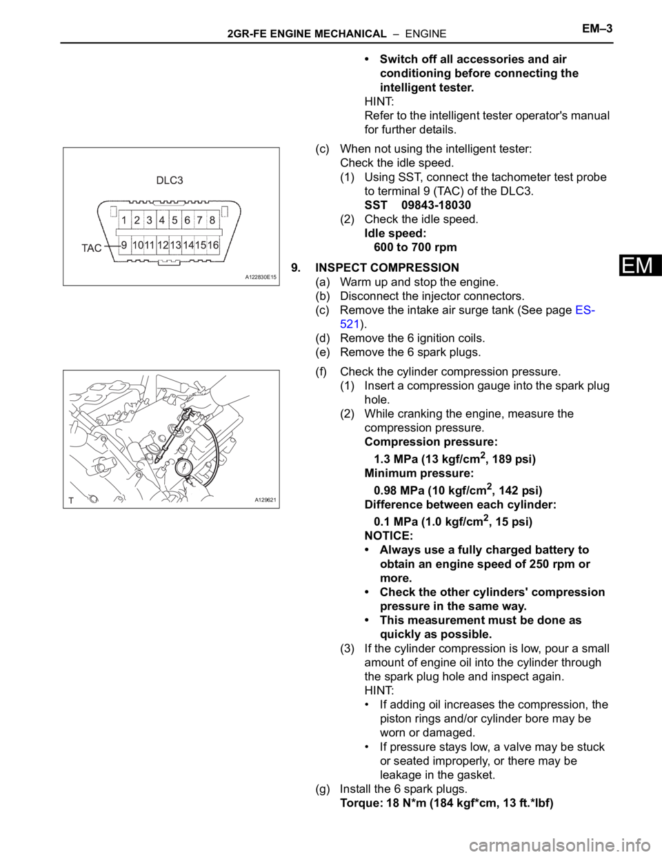
(c) When not using the intelligent tester:
Check the idle speed.
(1) Using SST, connect the tachometer test probe
to terminal 9 (TAC) of the DLC3.
SST 09843-18030
(2) Check the idle speed.
Idle speed:
600 to 700 rpm
9. INSPECT COMPRESSION
(a) Warm up and stop the engine.
(b) Disconnect the injector connectors.
(c) Remove the intake air surge tank (See page ES-
521).
(d) Remove the 6 ignition coils.
(e) Remove the 6 spark plugs.
(f) Check the cylinder compression pressure.
(1) Insert a compression gauge into the spark plug
hole.
(2) While cranking the engine, measure the
compression pressure.
Compression pressure:
1.3 MPa (13 kgf/cm
2, 189 psi)
Minimum pressure:
0.98 MPa (10 kgf/cm
2, 142 psi)
Difference between each cylinder:
0.1 MPa (1.0 kgf/cm
2, 15 psi)
NOTICE:
• Always use a fully charged battery to
obtain an engine speed of 250 rpm or
more.
• Check the other cylinders' compression
pressure in the same way.
• This measurement must be done as
quickly as possible.
(3) If the cylinder compression is low, pour a small
amount of engine oil into the cylinder through
the spark plug hole and inspect again.
HINT:
• If adding oil increases the compression, the
piston rings and/or cylinder bore may be
worn or damaged.
• If pressure stays low, a valve may be stuck
or seated improperly, or there may be
leakage in the gasket.
(g) Install the 6 spark plugs.
Torque: 18 N*m (184 kgf*cm, 13 ft.*lbf)
A122830E15
A129621
Page 934 of 3000

EM–42GR-FE ENGINE MECHANICAL – ENGINE
EM
(h) Install the 6 ignition coils.
Torque: 10 N*m (102 kgf*cm, 7 ft.*lbf)
(i) Install the intake air surge tank (See page ES-522).
10. INSPECT CO/HC
(a) Start the engine.
(b) Run the engine at 2500 rpm for approximately 180
seconds.
(c) Insert the CO/HC meter testing probe at least 40 cm
(1.3 ft.) into the tailpipe during idling.
(d) Check CO/HC concentration at idle and/or 2500
rpm.
HINT:
Check regulations and restrictions in your area
when performing 2 mode CO/HC concentration
testing (engine check at both idle speed and at 2500
rpm).
If the CO/HC concentration does not comply with
regulations, perform troubleshooting in the order
given below.
(1) Check air fuel ratio sensor and heated oxygen
sensor operation.
(2) See the table below for possible causes, and
then inspect and repair.
CO HC Problems Causes
Normal High Rough idle1. Faulty ignitions:
– Incorrect timing
– Fouled, shorted or improperly gapped plugs
2. Incorrect valve clearance
3. Leaks in intake and exhaust valves
4. Leaks in cylinders
Low HighRough idle
(fluctuating HC reading)1. Vacuum leaks:
– PCV hoses
– Intake manifold
– Throttle body
– Brake booster line
2. Lean mixture causing misfire
High HighRough idle
(black smoke from exhaust)1. Restricted air filter
2. Plugged PCV valve
3. Faulty SFI system:
– Faulty fuel pressure regulator
– Defective ECT sensor
– Defective MAF meter
–Faulty ECM
– Faulty injectors
– Faulty throttle position sensor