Page 2337 of 3000
TIRE AND WHEEL – TIRE PRESSURE WARNING VALVE AND TRANSMITTERTW–85
TW
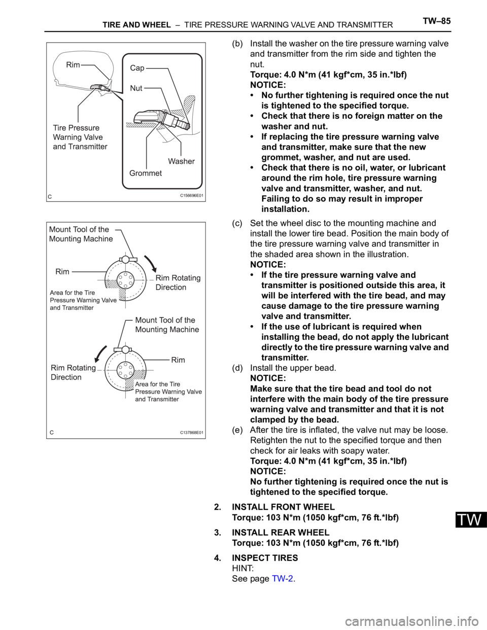
(b) Install the washer on the tire pressure warning valve
and transmitter from the rim side and tighten the
nut.
Torque: 4.0 N*m (41 kgf*cm, 35 in.*lbf)
NOTICE:
• No further tightening is required once the nut
is tightened to the specified torque.
• Check that there is no foreign matter on the
washer and nut.
• If replacing the tire pressure warning valve
and transmitter, make sure that the new
grommet, washer, and nut are used.
• Check that there is no oil, water, or lubricant
around the rim hole, tire pressure warning
valve and transmitter, washer, and nut.
Failing to do so may result in improper
installation.
(c) Set the wheel disc to the mounting machine and
install the lower tire bead. Position the main body of
the tire pressure warning valve and transmitter in
the shaded area shown in the illustration.
NOTICE:
• If the tire pressure warning valve and
transmitter is positioned outside this area, it
will be interfered with the tire bead, and may
cause damage to the tire pressure warning
valve and transmitter.
• If the use of lubricant is required when
installing the bead, do not apply the lubricant
directly to the tire pressure warning valve and
transmitter.
(d) Install the upper bead.
NOTICE:
Make sure that the tire bead and tool do not
interfere with the main body of the tire pressure
warning valve and transmitter and that it is not
clamped by the bead.
(e) After the tire is inflated, the valve nut may be loose.
Retighten the nut to the specified torque and then
check for air leaks with soapy water.
Torque: 4.0 N*m (41 kgf*cm, 35 in.*lbf)
NOTICE:
No further tightening is required once the nut is
tightened to the specified torque.
2. INSTALL FRONT WHEEL
Torque: 103 N*m (1050 kgf*cm, 76 ft.*lbf)
3. INSTALL REAR WHEEL
Torque: 103 N*m (1050 kgf*cm, 76 ft.*lbf)
4. INSPECT TIRES
HINT:
See page TW-2.
C156696E01
C137868E01
Page 2725 of 3000
PS–14POWER STEERING – VANE PUMP
PS
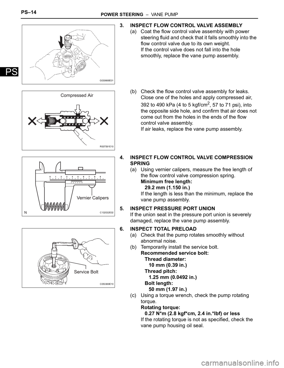
3. INSPECT FLOW CONTROL VALVE ASSEMBLY
(a) Coat the flow control valve assembly with power
steering fluid and check that it falls smoothly into the
flow control valve due to its own weight.
If the control valve does not fall into the hole
smoothly, replace the vane pump assembly.
(b) Check the flow control valve assembly for leaks.
Close one of the holes and apply compressed air,
392 to 490 kPa (4 to 5 kgf/cm
2, 57 to 71 psi), into
the opposite side hole, and confirm that air does not
come out from the holes in the ends of the flow
control valve assembly.
If air leaks, replace the vane pump assembly.
4. INSPECT FLOW CONTROL VALVE COMPRESSION
SPRING
(a) Using vernier calipers, measure the free length of
the flow control valve compression spring.
Minimum free length:
29.2 mm (1.150 in.)
If the length is less than the minimum, replace the
vane pump assembly.
5. INSPECT PRESSURE PORT UNION
If the union seat in the pressure port union is severely
damaged, replace the vane pump assembly.
6. INSPECT TOTAL PRELOAD
(a) Check that the pump rotates smoothly without
abnormal noise.
(b) Temporarily install the service bolt.
Recommended service bolt:
Thread diameter:
10 mm (0.39 in.)
Thread pitch:
1.25 mm (0.0492 in.)
Bolt length:
50 mm (1.97 in.)
(c) Using a torque wrench, check the pump rotating
torque.
Rotating torque:
0.27 N*m (2.8 kgf*cm, 2.4 in.*lbf) or less
If the rotating torque is not as specified, check the
vane pump housing oil seal.
G030668E01
R007591E10
C132032E02
C053369E10
Page 2915 of 3000
AIR CONDITIONING – REFRIGERANTAC–171
AC
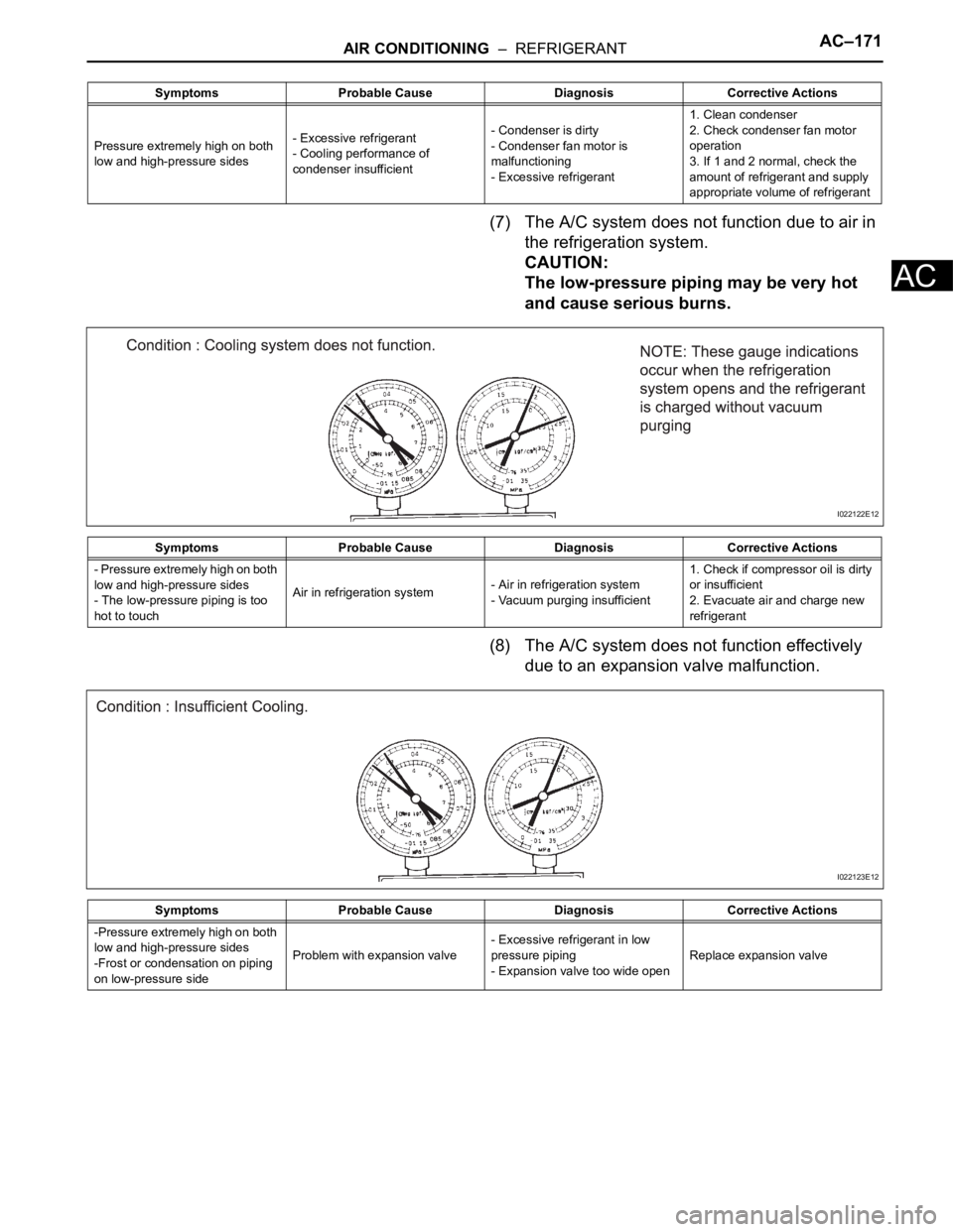
(7) The A/C system does not function due to air in
the refrigeration system.
CAUTION:
The low-pressure piping may be very hot
and cause serious burns.
(8) The A/C system does not function effectively
due to an expansion valve malfunction.
Symptoms Probable Cause Diagnosis Corrective Actions
Pressure extremely high on both
low and high-pressure sides- Excessive refrigerant
- Cooling performance of
condenser insufficient- Condenser is dirty
- Condenser fan motor is
malfunctioning
- Excessive refrigerant1. Clean condenser
2. Check condenser fan motor
operation
3. If 1 and 2 normal, check the
amount of refrigerant and supply
appropriate volume of refrigerant
Symptoms Probable Cause Diagnosis Corrective Actions
- Pressure extremely high on both
low and high-pressure sides
- The low-pressure piping is too
hot to touchAir in refrigeration system- Air in refrigeration system
- Vacuum purging insufficient1. Check if compressor oil is dirty
or insufficient
2. Evacuate air and charge new
refrigerant
I022122E12
Symptoms Probable Cause Diagnosis Corrective Actions
-Pressure extremely high on both
low and high-pressure sides
-Frost or condensation on piping
on low-pressure sideProblem with expansion valve- Excessive refrigerant in low
pressure piping
- Expansion valve too wide openReplace expansion valve
I022123E12
Page:
< prev 1-8 9-16 17-24