2007 TOYOTA SIENNA tire size
[x] Cancel search: tire sizePage 173 of 3000
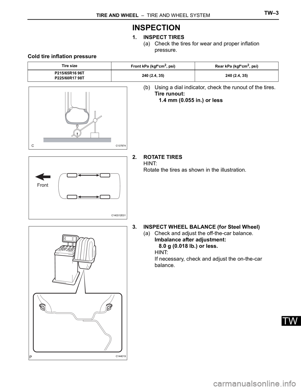
TIRE AND WHEEL – TIRE AND WHEEL SYSTEMTW–3
TW
INSPECTION
1. INSPECT TIRES
(a) Check the tires for wear and proper inflation
pressure.
Cold tire inflation pressure
(b) Using a dial indicator, check the runout of the tires.
Tire runout:
1.4 mm (0.055 in.) or less
2. ROTATE TIRES
HINT:
Rotate the tires as shown in the illustration.
3. INSPECT WHEEL BALANCE (for Steel Wheel)
(a) Check and adjust the off-the-car balance.
Imbalance after adjustment:
8.0 g (0.018 lb.) or less.
HINT:
If necessary, check and adjust the on-the-car
balance.
Tire size
Front kPa (kgf*cm2, psi) Rear kPa (kgf*cm2, psi)
P215/65R16 96T
P225/60R17 98T240 (2.4, 35) 240 (2.4, 35)
C137874
C140312E01
C144019
Page 2192 of 3000
SUSPENSION – REAR WHEEL ALIGNMENTSP–9
SP
REAR WHEEL ALIGNMENT
ADJUSTMENT
NOTICE:
For vehicles equipped with VSC, if wheel alignment has
been adjusted, and if suspension or underbody
components have been removed/installed or replaced, be
sure to perform the following initialization procedure in
order for the system to function normally:
1. Disconnect the negative battery terminal for more
than 2 seconds.
2. Reconnect the negative battery terminal.
3. Perform zero point calibration of the yaw rate and
acceleration sensor and test mode inspection.
HINT:
(See page BC-70)
1. INSPECT TIRE
HINT:
(See page TW-2)
2. MEASURE VEHICLE HEIGHT
NOTICE:
Before inspecting the wheel alignment, adjust the
vehicle height to the specified valve.
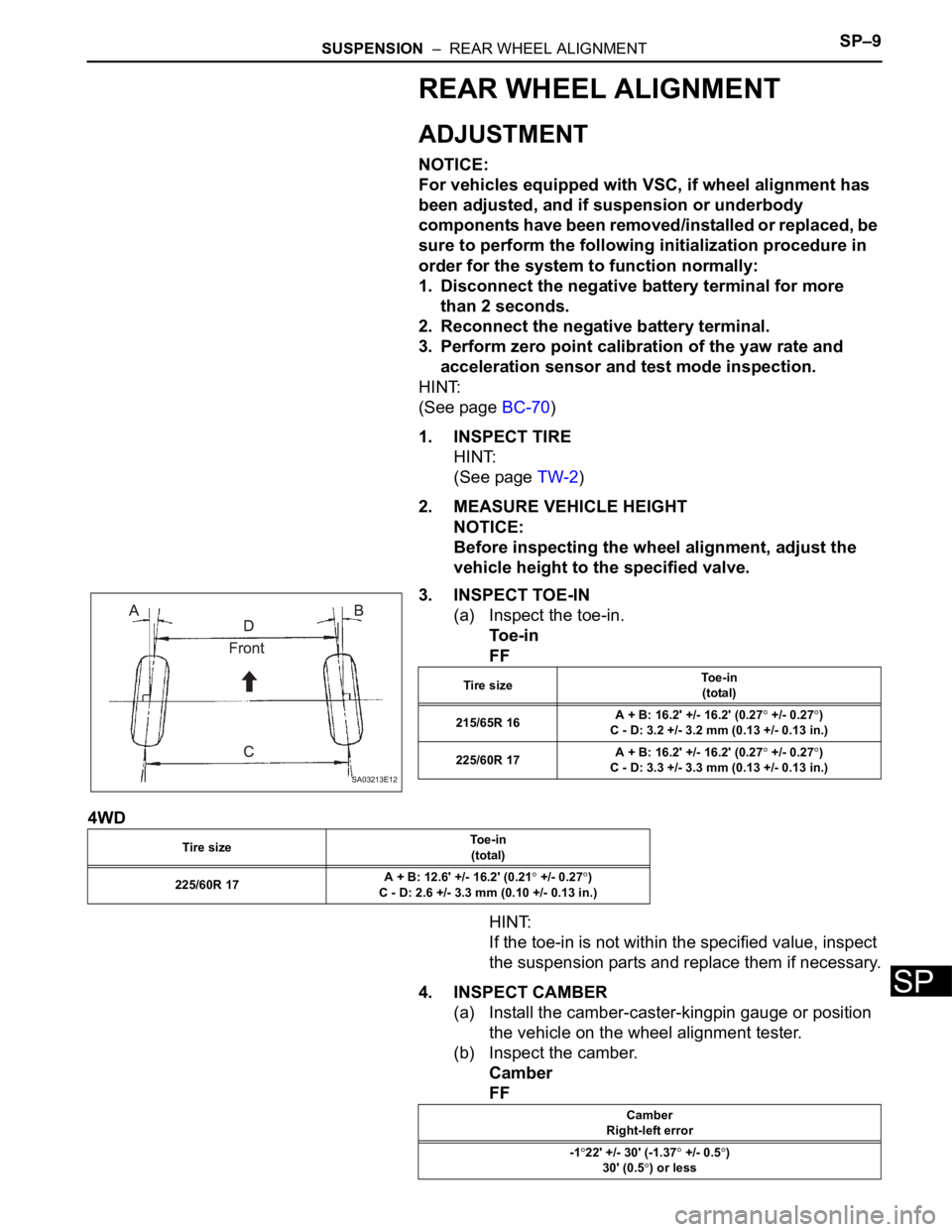
3. INSPECT TOE-IN
(a) Inspect the toe-in.
To e - i n
FF
4WD
HINT:
If the toe-in is not within the specified value, inspect
the suspension parts and replace them if necessary.
4. INSPECT CAMBER
(a) Install the camber-caster-kingpin gauge or position
the vehicle on the wheel alignment tester.
(b) Inspect the camber.
Camber
FF
SA03213E12
Tire sizeTo e - i n
(total)
215/65R 16A + B: 16.2' +/- 16.2' (0.27
+/- 0.27)
C - D: 3.2 +/- 3.2 mm (0.13 +/- 0.13 in.)
225/60R 17A + B: 16.2' +/- 16.2' (0.27
+/- 0.27)
C - D: 3.3 +/- 3.3 mm (0.13 +/- 0.13 in.)
Tire sizeTo e - i n
(total)
225/60R 17A + B: 12.6' +/- 16.2' (0.21
+/- 0.27)
C - D: 2.6 +/- 3.3 mm (0.10 +/- 0.13 in.)
Camber
Right-left error
-1
22' +/- 30' (-1.37 +/- 0.5)
30' (0.5
) or less
Page 2254 of 3000
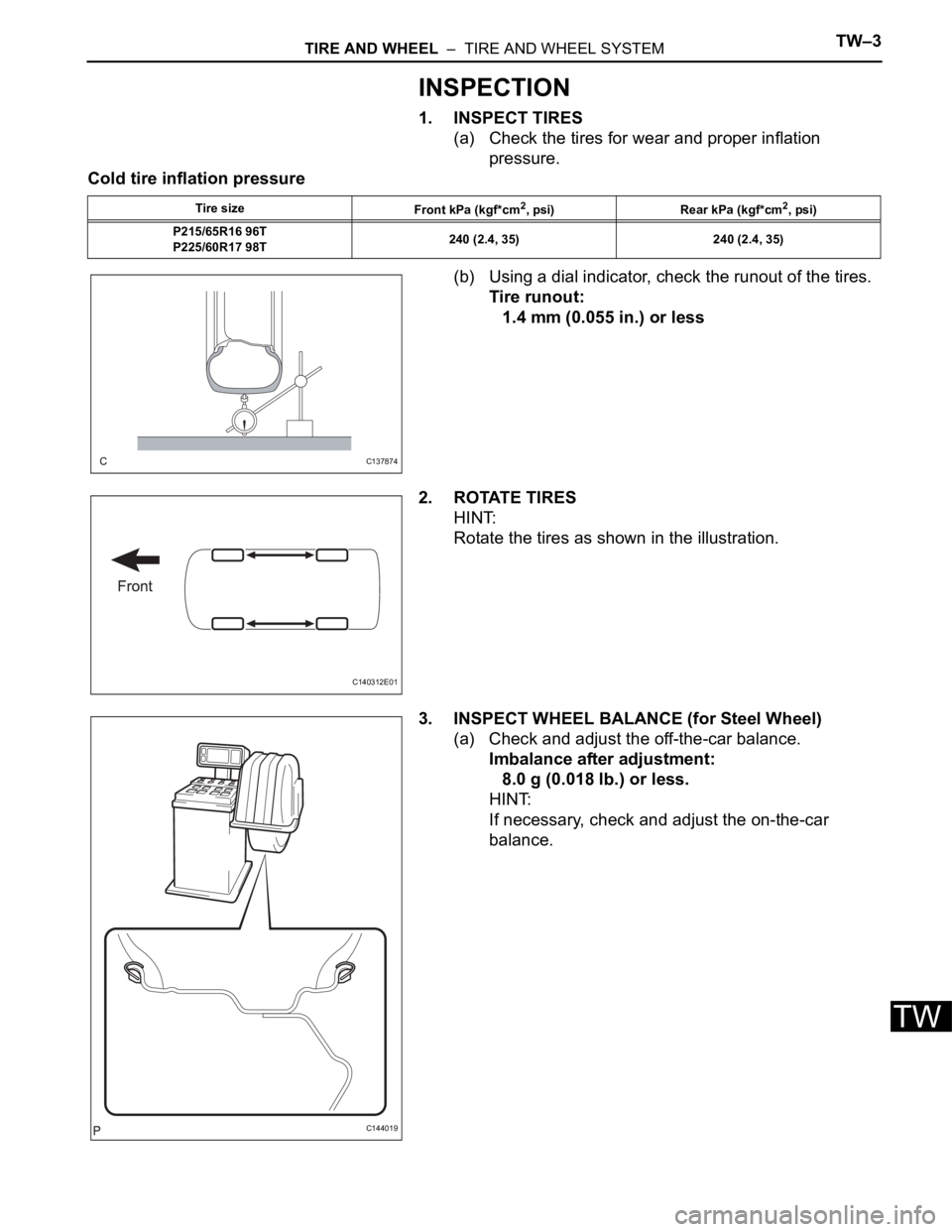
TIRE AND WHEEL – TIRE AND WHEEL SYSTEMTW–3
TW
INSPECTION
1. INSPECT TIRES
(a) Check the tires for wear and proper inflation
pressure.
Cold tire inflation pressure
(b) Using a dial indicator, check the runout of the tires.
Tire runout:
1.4 mm (0.055 in.) or less
2. ROTATE TIRES
HINT:
Rotate the tires as shown in the illustration.
3. INSPECT WHEEL BALANCE (for Steel Wheel)
(a) Check and adjust the off-the-car balance.
Imbalance after adjustment:
8.0 g (0.018 lb.) or less.
HINT:
If necessary, check and adjust the on-the-car
balance.
Tire size
Front kPa (kgf*cm2, psi) Rear kPa (kgf*cm2, psi)
P215/65R16 96T
P225/60R17 98T240 (2.4, 35) 240 (2.4, 35)
C137874
C140312E01
C144019
Page 2263 of 3000

TIRE AND WHEEL – TIRE PRESSURE WARNING SYSTEMTW–25
TW
INITIALIZATION
1. DESCRIPTION OF INITIALIZATION
(a) Perform initialization in the following cases:
• Before delivery of a new vehicle.
• After replacement of the tire pressure warning
ECU*.
• After replacement of the tire pressure warning
valve and transmitter.
• Specified tire pressure changes depending on
the size or type of the tire.
*: Perform initialization after the transmitter ID
registration is completed (See page TW-20).
(b) Before initialization
(1) Set the air pressure of all tires to the specified
value.
Cold tire inflation pressure
NOTICE:
Perform the tire pressure adjustment after
the vehicle has sufficiently cooled down. If
the vehicle is not sufficiently cooled down,
increase the air pressure by 20 to 30 kPa (0.2
to 0.3 kgf/cm
2, 2.9 to 4.3 psi) above the
specified value.
Tire Size
kPa (kgf/cm2, psi)
P215/65R16
240 (2.4, 35)
P225/60R17
Page 2268 of 3000
TW–10TIRE AND WHEEL – TIRE PRESSURE WARNING SYSTEM
TW
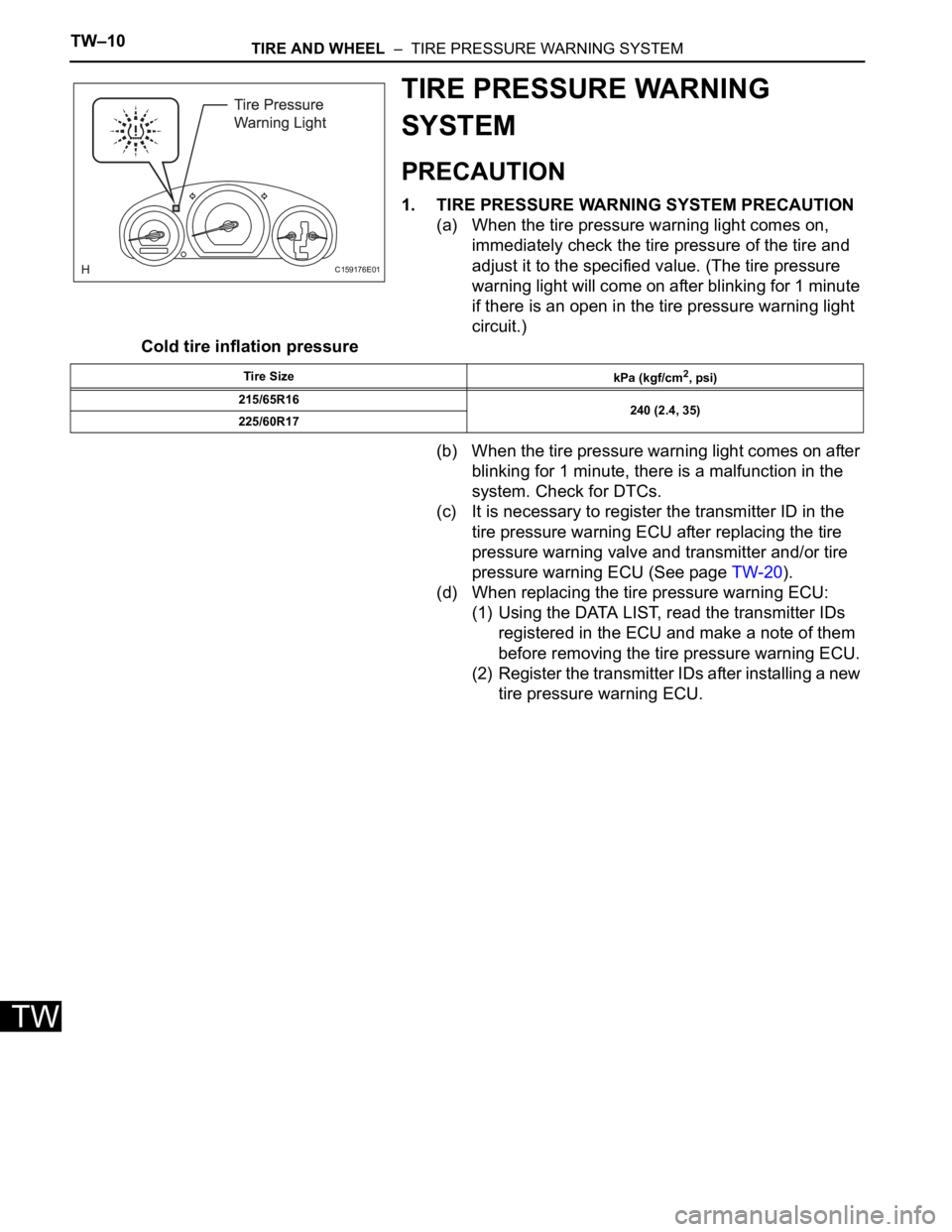
TIRE PRESSURE WARNING
SYSTEM
PRECAUTION
1. TIRE PRESSURE WARNING SYSTEM PRECAUTION
(a) When the tire pressure warning light comes on,
immediately check the tire pressure of the tire and
adjust it to the specified value. (The tire pressure
warning light will come on after blinking for 1 minute
if there is an open in the tire pressure warning light
circuit.)
Cold tire inflation pressure
(b) When the tire pressure warning light comes on after
blinking for 1 minute, there is a malfunction in the
system. Check for DTCs.
(c) It is necessary to register the transmitter ID in the
tire pressure warning ECU after replacing the tire
pressure warning valve and transmitter and/or tire
pressure warning ECU (See page TW-20).
(d) When replacing the tire pressure warning ECU:
(1) Using the DATA LIST, read the transmitter IDs
registered in the ECU and make a note of them
before removing the tire pressure warning ECU.
(2) Register the transmitter IDs after installing a new
tire pressure warning ECU.
C159176E01
Tire Size
kPa (kgf/cm2, psi)
215/65R16
240 (2.4, 35)
225/60R17
Page 2284 of 3000

TW–42TIRE AND WHEEL – TIRE PRESSURE WARNING SYSTEM
TW
DESCRIPTION
The tire pressure warning valve and transmitters that are installed in the tire and wheel assemblies
measure the air pressures of the tires. The measured values are transmitted to the tire pressure warning
antenna and receiver on the body as radio waves and then sent to the tire pressure warning ECU. The
ECU compares the measured air pressure values with the air pressure threshold. When the measured air
pressure value is less than this threshold, the warning light in the combination meter comes on. The tire
pressure warning ECU stores a DTC when the tire pressure warning valve and transmitter stops
transmitting signals. At this time, forcibly transmit the signals by releasing the tire pressure rapidly. The
stored DTC is cleared when the signal transmission is resumed.
HINT:
It is necessary to perform the procedure to identify the tire pressure warning valve and transmitter that is
malfunctioning because it cannot be identified by the output DTC.
INSPECTION PROCEDURE
NOTICE:
It is necessary to perform initialization (See page TW-23) after registration (See page TW-20) of the
transmitter IDs into the tire pressure warning ECU after the ECU and/or valve and transmitter have
been replaced.
(a) Set the tire pressure to the specified value.
Cold tire inflation pressure
(b) Make sure that the ignition switch is off.
(c) Connect the intelligent tester to the DLC3.
(d) Turn the ignition switch to the ON position and turn the
tester on.
DTC C2111/11 Transmitter ID1 Operation Stop
DTC C2112/12 Transmitter ID2 Operation Stop
DTC C2113/13 Transmitter ID3 Operation Stop
DTC C2114/14 Transmitter ID4 Operation Stop
DTC No. DTC Detection Condition Trouble Area
C 2 111 / 11
C2112/12
C2113/13
C2114/14Tire pressure warning valve and transmitters stop
transmitting signals• Tire pressure warning valve and transmitter
• Tire pressure warning ECU
1PERFORM FORCED TRANSMISSION OF TRANSMITTER ID OF ALL WHEELS
Tire Size
kPa (kgf/cm2, psi)
P215/65R16
240 (2.4, 35)
P225/60R17
Page 2289 of 3000
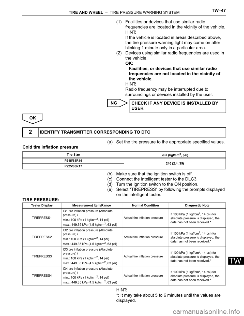
TIRE AND WHEEL – TIRE PRESSURE WARNING SYSTEMTW–47
TW
(1) Facilities or devices that use similar radio
frequencies are located in the vicinity of the vehicle.
HINT:
If the vehicle is located in areas described above,
the tire pressure warning light may come on after
blinking 1 minute only in a particular area.
(2) Devices using similar radio frequencies are used in
the vehicle.
OK:
Facilities, or devices that use similar radio
frequencies are not located in the vicinity of
the vehicle.
HINT:
Radio frequency may be interrupted due to
surroundings or devices installed by the user.
NG
OK
(a) Set the tire pressure to the appropriate specified values.
Cold tire inflation pressure
(b) Make sure that the ignition switch is off.
(c) Connect the intelligent tester to the DLC3.
(d) Turn the ignition switch to the ON position.
(e) Select "TIREPRESS" by following the prompts displayed
on the intelligent tester.
TIRE PRESSURE:
HINT:
*: It may take about 5 to 6 minutes until the values are
displayed.CHECK IF ANY DEVICE IS INSTALLED BY
USER
2IDENTIFY TRANSMITTER CORRESPONDING TO DTC
Tire Size
kPa (kgf/cm2, psi)
P215/65R16
240 (2.4, 35)
P225/60R17
Tester Display Measurement Item/Range Normal Condition Diagnostic Note
TIREPRESS1ID1 tire inflation pressure (Absolute
pressure) /
min.: 100 kPa (1 kgf/cm
2, 14 psi)
max.: 449.35 kPa (4.5 kgf/cm2, 63 psi)Actual tire inflation pressureIf 100 kPa (1 kgf/cm
2, 14 psi) for
absolute pressure is displayed, the
data has not been received.*
TIREPRESS2ID2 tire inflation pressure (Absolute
pressure) /
min.: 100 kPa (1 kgf/cm
2, 14 psi)
max.: 449.35 kPa (4.5 kgf/cm2, 63 psi)Actual tire inflation pressureIf 100 kPa (1 kgf/cm
2, 14 psi) for
absolute pressure is displayed, the
data has not been received.*
TIREPRESS3ID3 tire inflation pressure (Absolute
pressure) /
min.: 100 kPa (1 kgf/cm
2, 14 psi)
max.: 449.35 kPa (4.5 kgf/cm2, 63 psi)Actual tire inflation pressureIf 100 kPa (1 kgf/cm
2, 14 psi) for
absolute pressure is displayed, the
data has not been received.*
TIREPRESS4ID4 tire inflation pressure (Absolute
pressure) /
min.: 100 kPa (1 kgf/cm
2, 14 psi)
max.: 449.35 kPa (4.5 kgf/cm2, 63 psi)Actual tire inflation pressureIf 100 kPa (1 kgf/cm
2, 14 psi) for
absolute pressure is displayed, the
data has not been received.*
Page 2295 of 3000

TIRE AND WHEEL – TIRE PRESSURE WARNING SYSTEMTW–53
TW
DESCRIPTION
The tire pressure warning valve and transmitters that are installed in the tire and wheel assemblies
measure the air pressure of the tires. The measured values are transmitted to the tire pressure warning
antenna and receiver on the body as radio waves and then sent to the tire pressure warning ECU. The
ECU compares the measured air pressure values with the air pressure threshold. When the measured air
pressure value is less than this threshold, the warning light in the combination meter comes on.
When the internal circuit of the tire pressure warning valve and transmitter is malfunctioning, this DTC is
output.
HINT:
It is necessary to perform the procedure to identify the tire pressure warning valve and transmitter that is
malfunctioning because it cannot be identified by the output DTC.
INSPECTION PROCEDURE
NOTICE:
• When replacing the tire pressure warning ECU, read the IDs stored in the ECU using the
intelligent tester and write them down before removal.
• It is necessary to perform initialization (See page TW-23) after registration (See page TW-20) of
the transmitter IDs into the tire pressure warning ECU after the ECU and/or valve and
transmitter have been replaced.
(a) Set the tire pressure to the specified value.
Cold tire inflation pressure
(b) Make sure that the ignition switch is off.
(c) Connect the intelligent tester to the DLC3.
(d) Turn the ignition switch to the ON position.
(e) Display the "TIREPRESS" data for each wheel using the
intelligent tester.
DTC C2141/41 Transmitter ID1 Error
DTC C2142/42 Transmitter ID2 Error
DTC C2143/43 Transmitter ID3 Error
DTC C2144/44 Transmitter ID4 Error
DTC No. DTC Detection Condition Trouble Area
C2141/41
C2142/42
C2143/43
C2144/44The battery of the valve and transmitter is expired.• Tire pressure warning valve and transmitter
• Tire pressure warning ECU
1IDENTIFY TRANSMITTER CORRESPONDING TO DTC
Tire Size
kPa (kgf/cm2, psi)
P215/65R16
240 (2.4, 35)
P225/60R17